 Zalmotek
So how does it work?
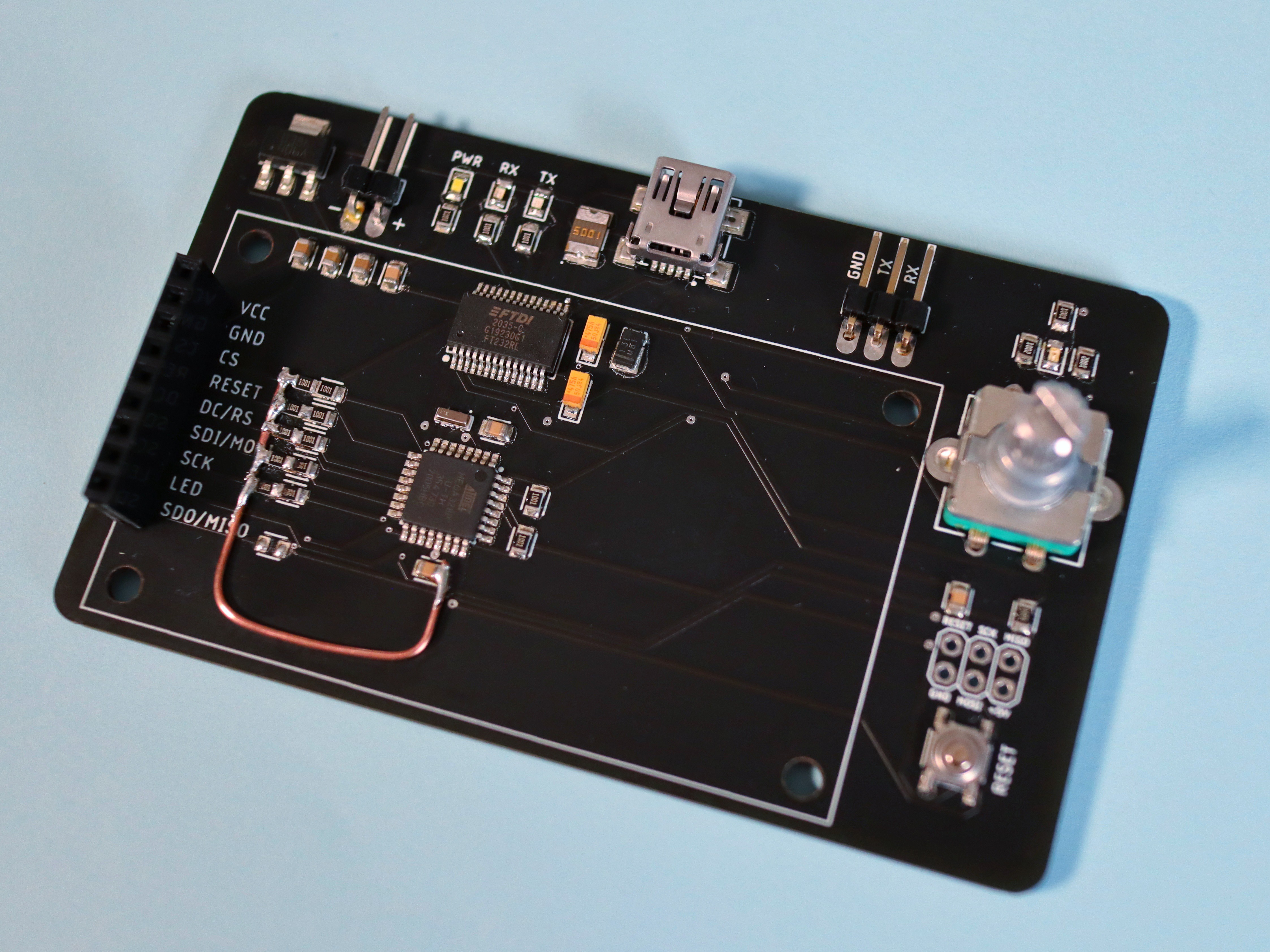
On the upper right corner, there's a pin header (RX, TX, GND) meant to be connected to the device you want to receive data from. The current iteration is only 5V tolerant, in the future we plan to add a switch to shift between the 5V and 3.3V logic levels.
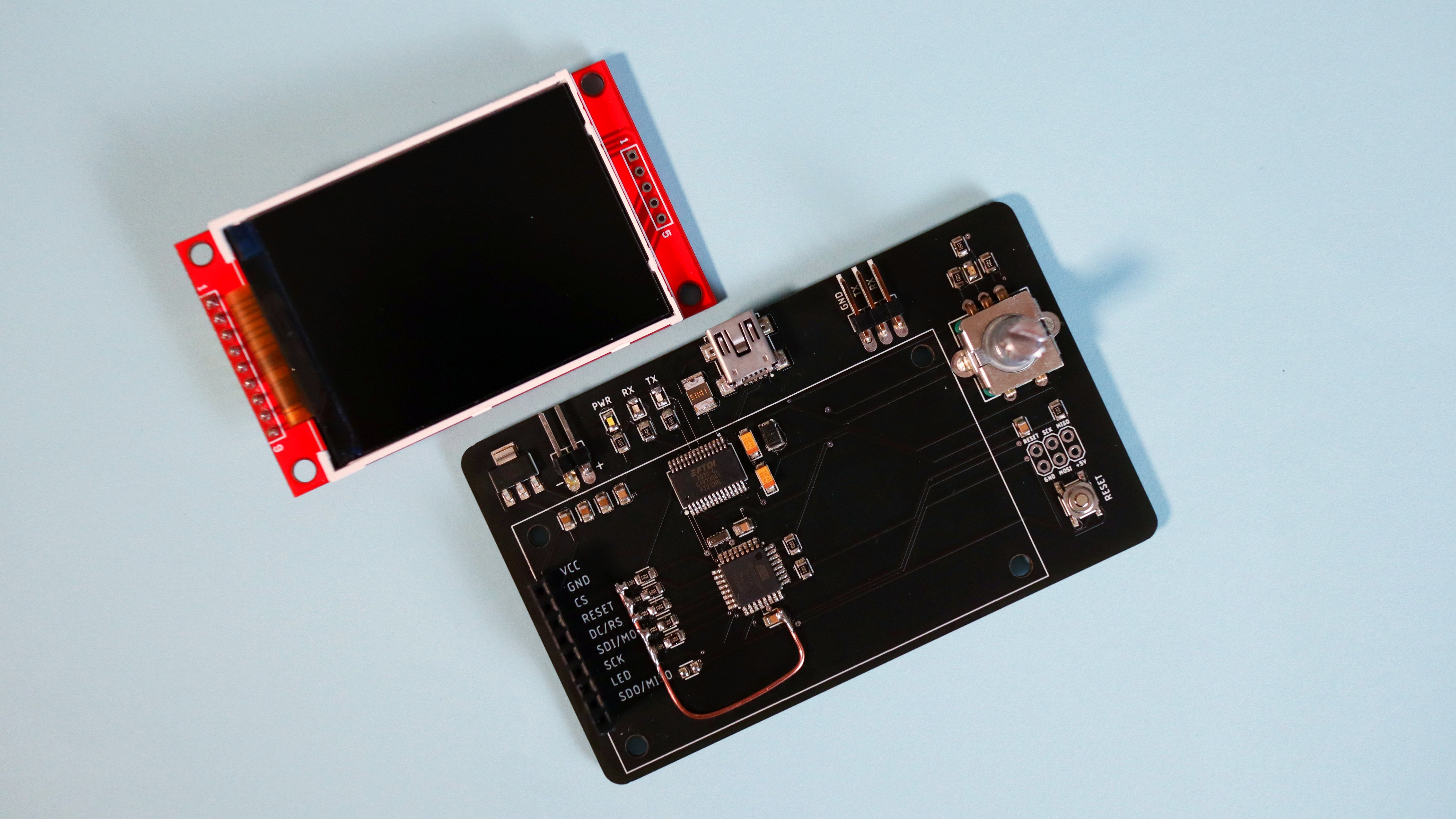
We've used an ILI93441 2.2" TFT display and an ATmega328P microcontroller (the design is based on the Arduino Nano schematic) for reading and displaying the serial data. We've also added a rotary encoder with push button, which can be used to switch between different baud rates, scroll through the text or pause/resume autoscrolling.
We've ordered the PCBs from JLCPCB in matte back and, as it sometimes happens with first prototypes, some things needed to be fixed :") The display we've used is only 3.3V tolerant and most tutorials recommended adding 1k resistors in series with the data pins when used with a 5V microcontroller. That didn't work though, so we've had to add more resistors to complete the voltage divider. But there's nothing that some patience and copper wire can't fix! (Putting to use all the skills from circuit sculpting :P).
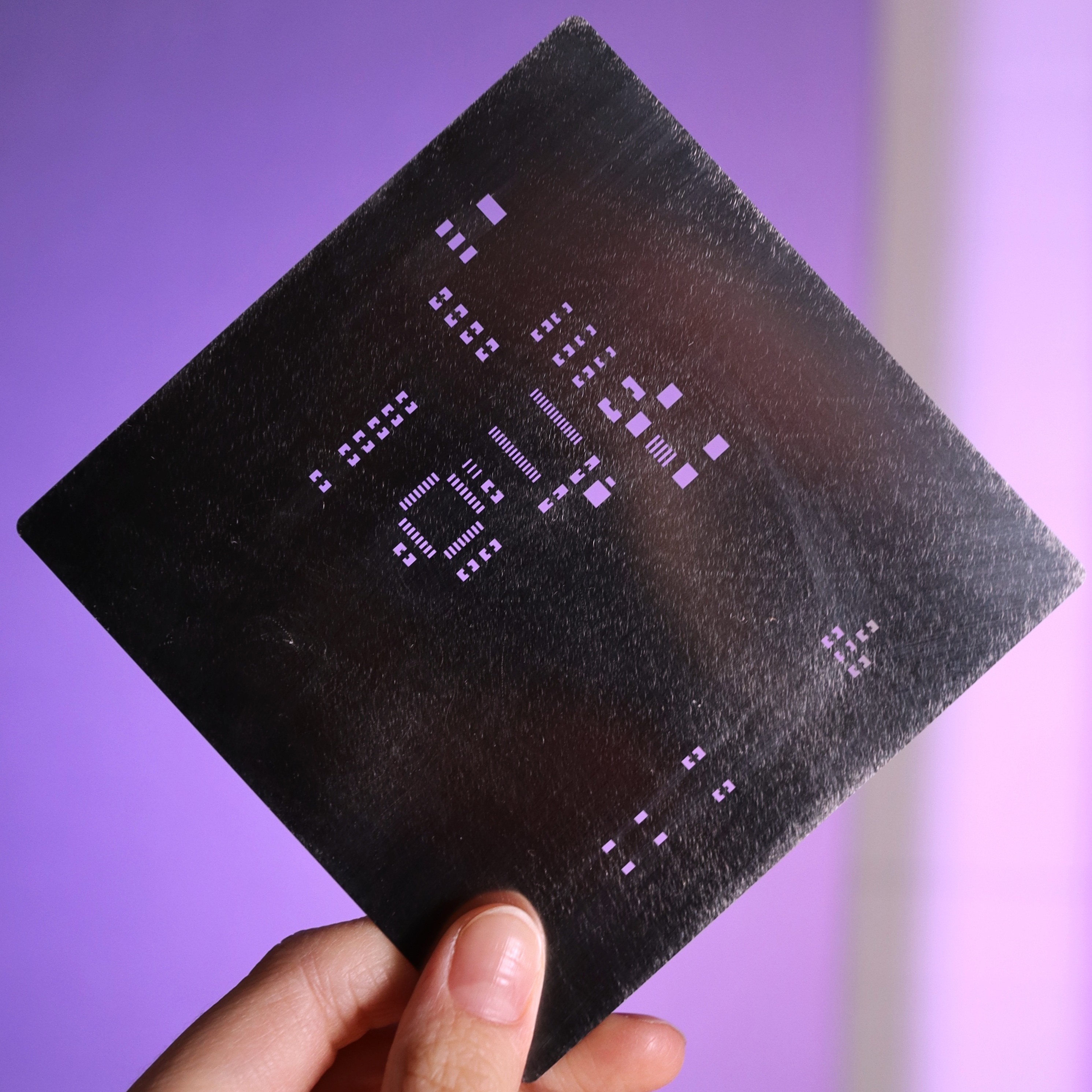
Since the PCBs are quite small, we've ordered a custom-sized stencil, which is easier to use than the default one (which is huge). The other good part is that it got shipped together with the PCBs!
Here's a short assembly video:
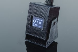
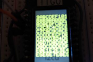
And here's a quick test with it:

As this was just a quick prototype, we still have to implement some useful features, so some plans for the future would be:
- changing the ATmega328P microcontroller for a Raspberry Pi Pico, for faster readings
- implementing additional software features, such as rotating the display, changing the baud rate through the encoder, scrolling back etc.
- adding a switch for shifting between the 5V and 3.3V logic levels.
The code used for this project is based on the following resources:
- The ILI9341 Arduino Library: https://github.com/Bodmer/TFT_ILI9341


 ACROBOTIC Industries
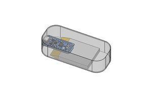
 PointyOintment
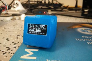
 honey the codewitch
It is mentioned in the description of the project.
We will upload a new code and do some of our customization soon and will upload that too.