 Dominik Meffert
For the last weeks, I was searching for a way to generate a sine wave signal for driving the piezo and a 0-5V square wave signal for driving the LED strobe with the same timing to prevent a "moving droplet effect".
After trying out many things that didn't work I have to thank @Paulo Campos for the great help and for pointing me out that I can use a comparator to turn the sine wave signal into a square wave signal with the same timing.
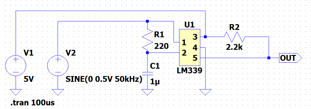
Since this project requires dealing with electrical circuits more intensively, I thought of using LTspice for drawing and simulating the circuits that I want to build.
While the electronics that I used for my former projects were mostly simple, based on Arduino projects or based on other open source projects, the CIJ printer project will be a bit more complicated, because there is not much information about the electronics of CIJ printers available and so I have to figure it out by myself.
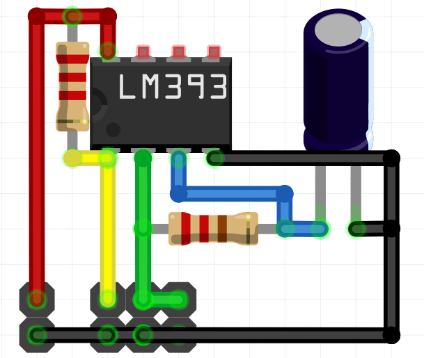
So with the tip of using a comparator, I ordered some ICs, including the LM339 and LM393 comparators, and searched the internet for circuits that I can test out, modify and simulate in LTspice.
It took me a while, but I came up with a circuit that had the desired output in the simulation.
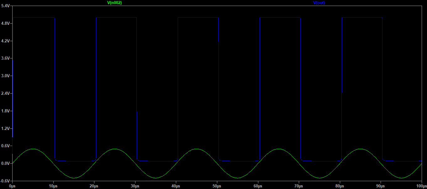
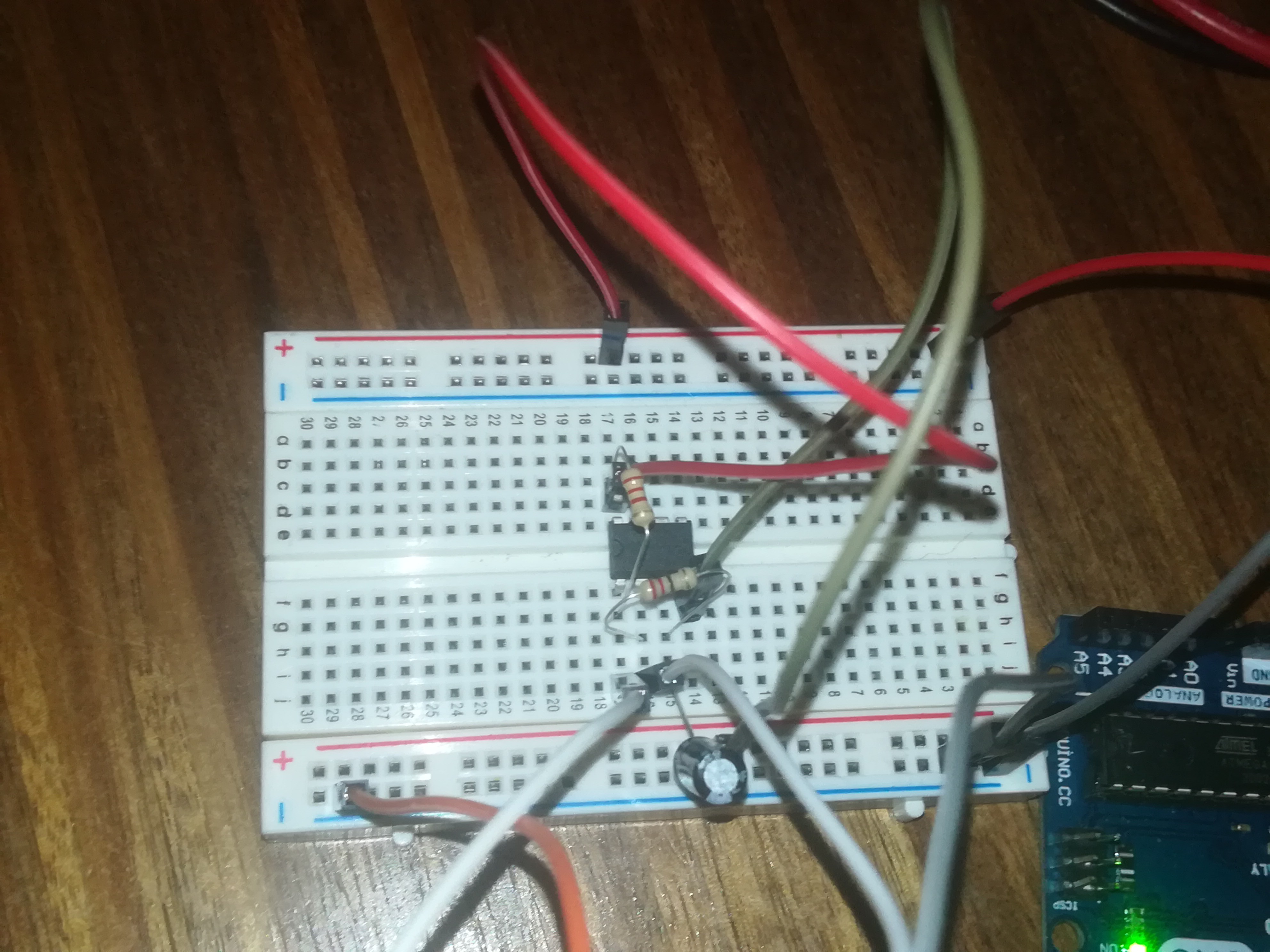
After simulating it, I tried to build it on a breadboard and measure the real circuit with an oscilloscope.
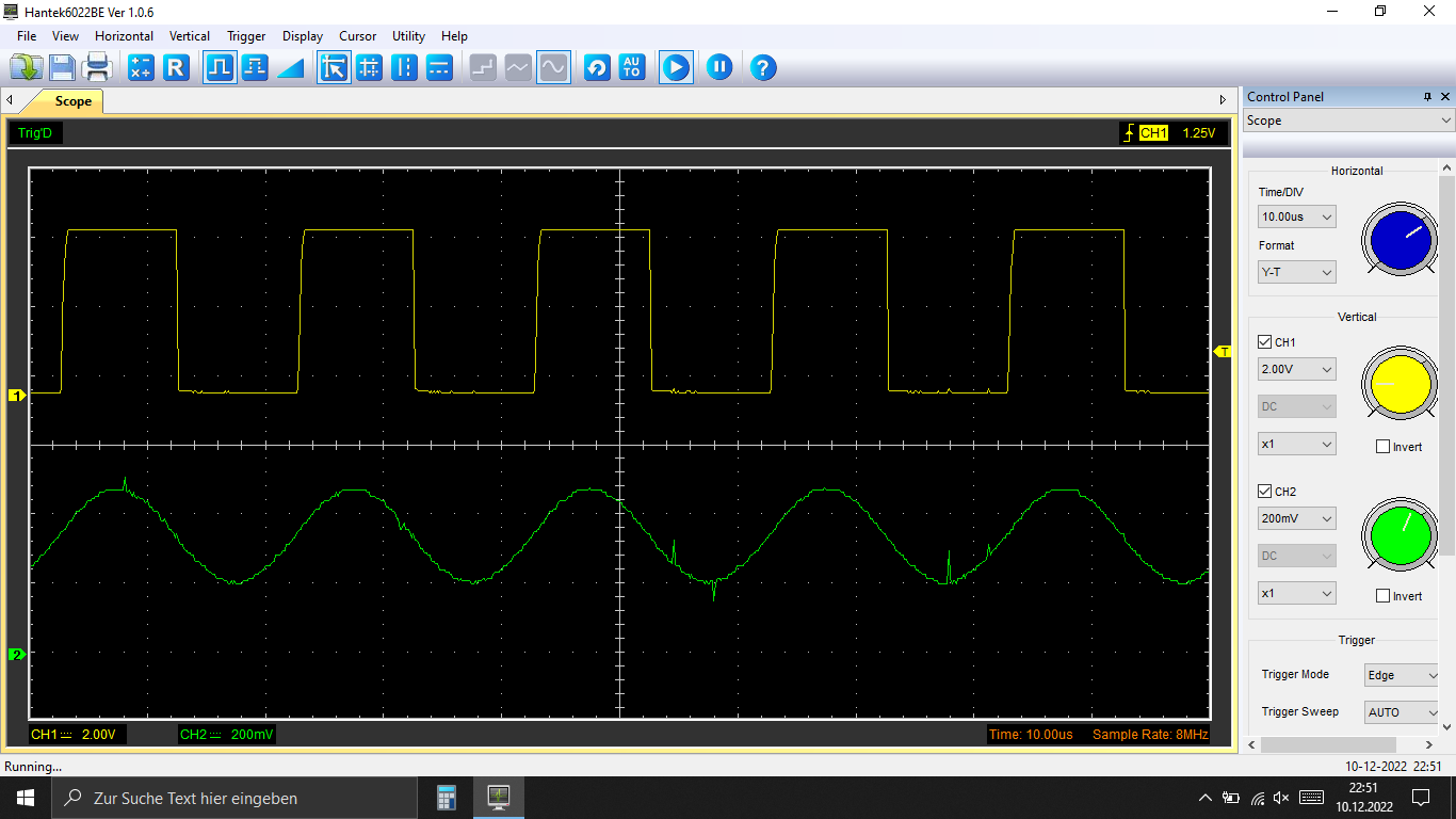
The spikes in the sine wave were caused by the notebook's power supply.
I got the desired output and so I drew the layout for a perf board and soldered it together.
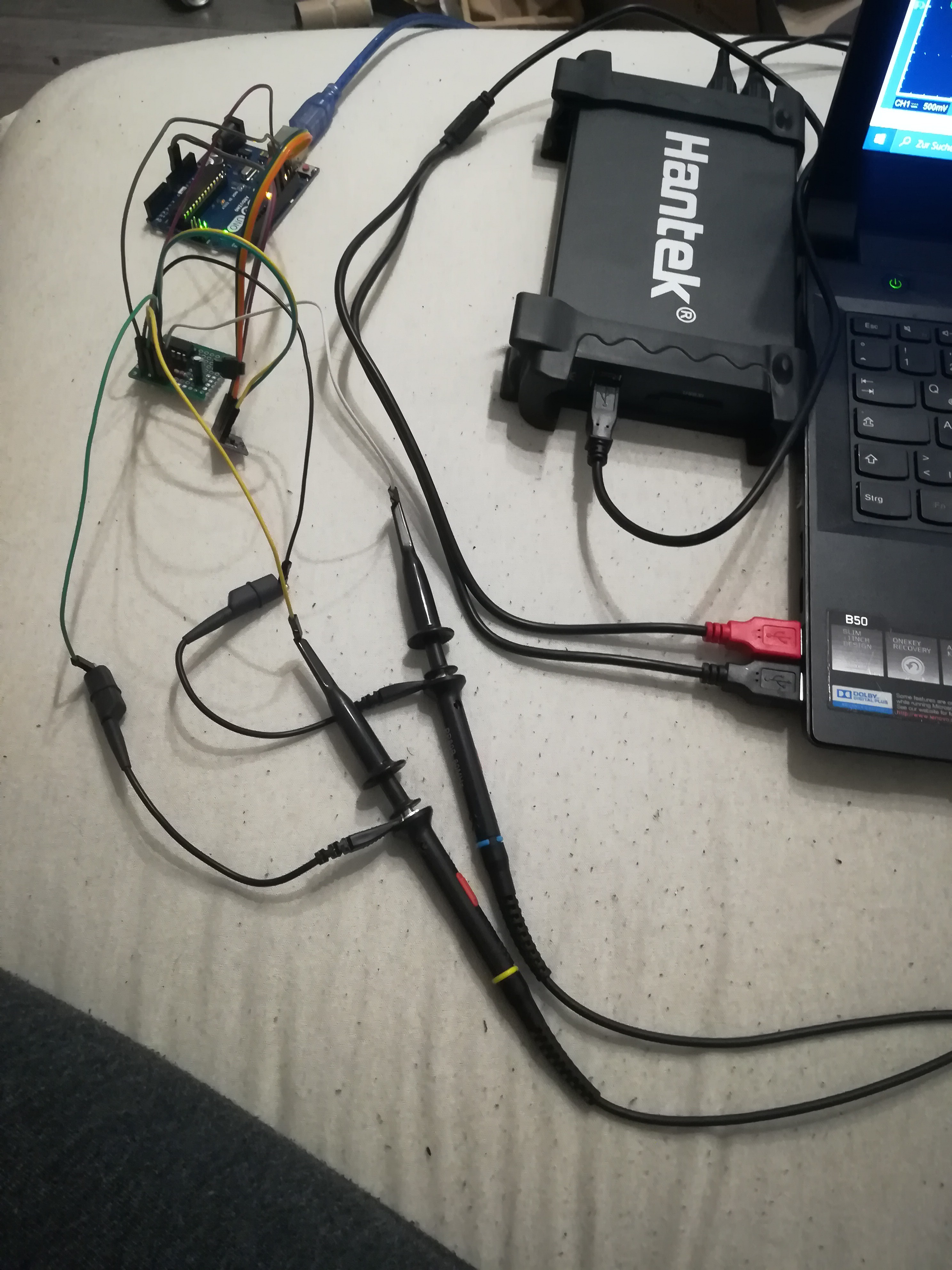
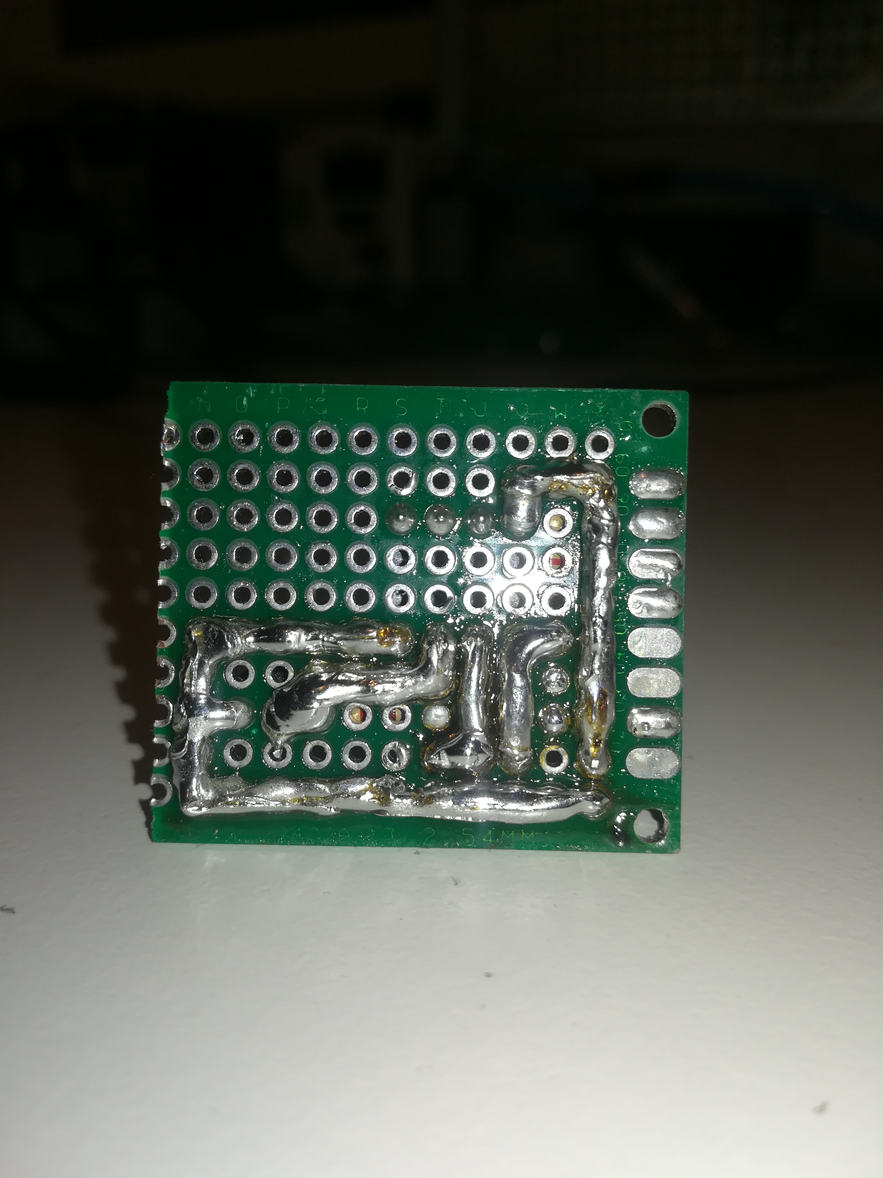
After that, I connected everything for doing some testing with it.
The setup for testing looked a bit messy.
I tested out different piezos from ultrasonic cleaners. I heard that the optimal frequency for a 0.1mm nozzle at 40psi is around 48kHz to 50kHz and because of that, I bought ultrasonic cleaners that claimed to run at 50kHz. Unfortunately, there is no guarantee that the ultrasonic cleaners contain piezos that can run on the claimed frequency and so you have to be lucky to get a good one.
The piezo from the second ultrasonic cleaner that I tried contained a piezo that could run at 48kHz even though it was not its resonance frequency.
I tested the vibration of the piezo by sticking another smaller piezo on top of them and measuring its output with an oscilloscope. After sticking the smaller piezo on top and connecting the oscilloscope I tried out different frequencies from 40kHz to 50kHz to see at which frequency I can measure the highest voltage reading on the small piezo. This frequency should then be the piezo's resonance frequency. The first piezo that I tried worked best at 43kHz and the second one worked best at 47kHz, but it also worked not that bad at 48kHz, so I used it for further testing.
I carefully clamped it on top of the nozzle and looked at the ink stream under the LED strobe.
And it worked: Visible ink stream separation under the LED strobe at 48kHz.
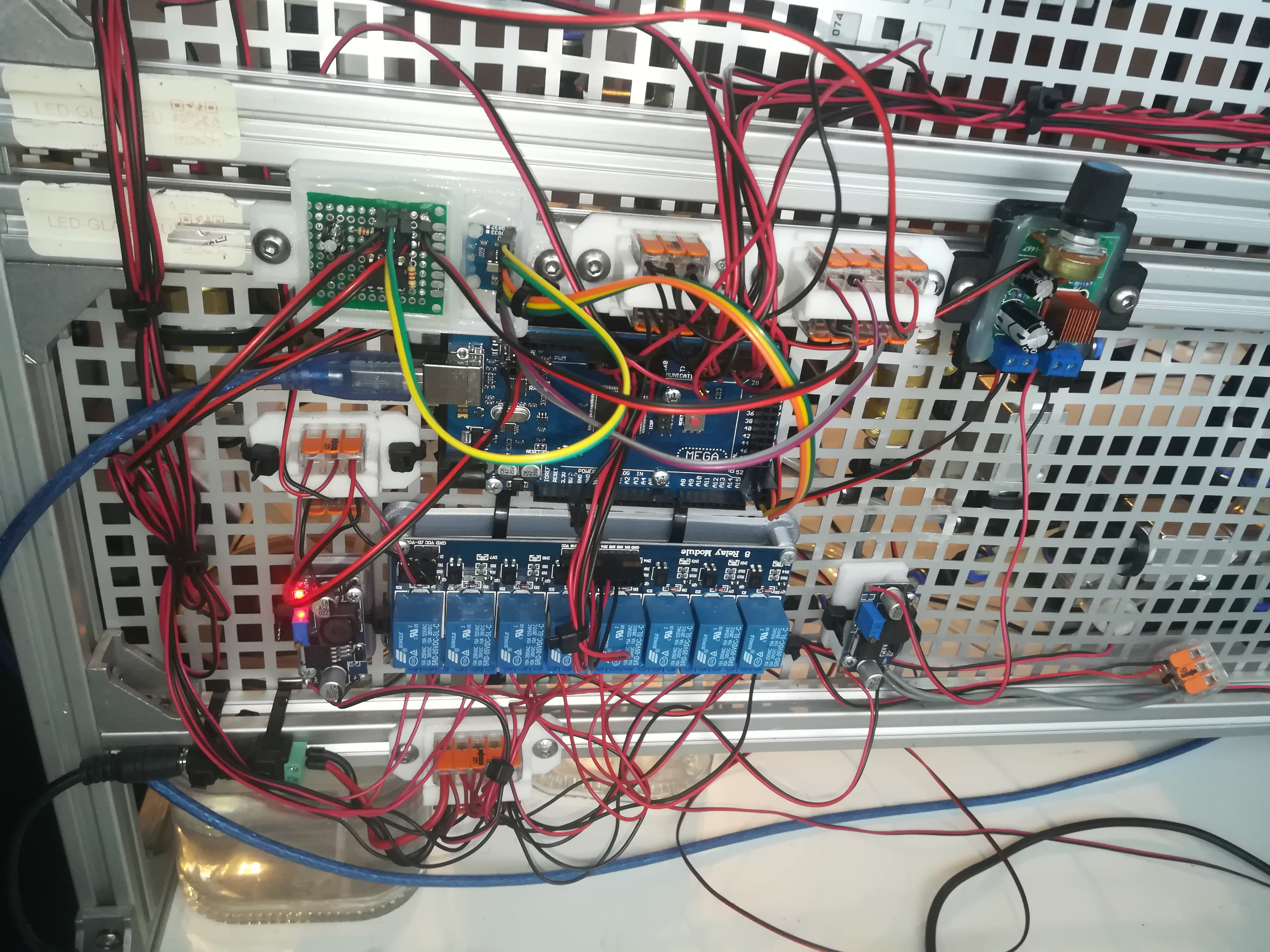
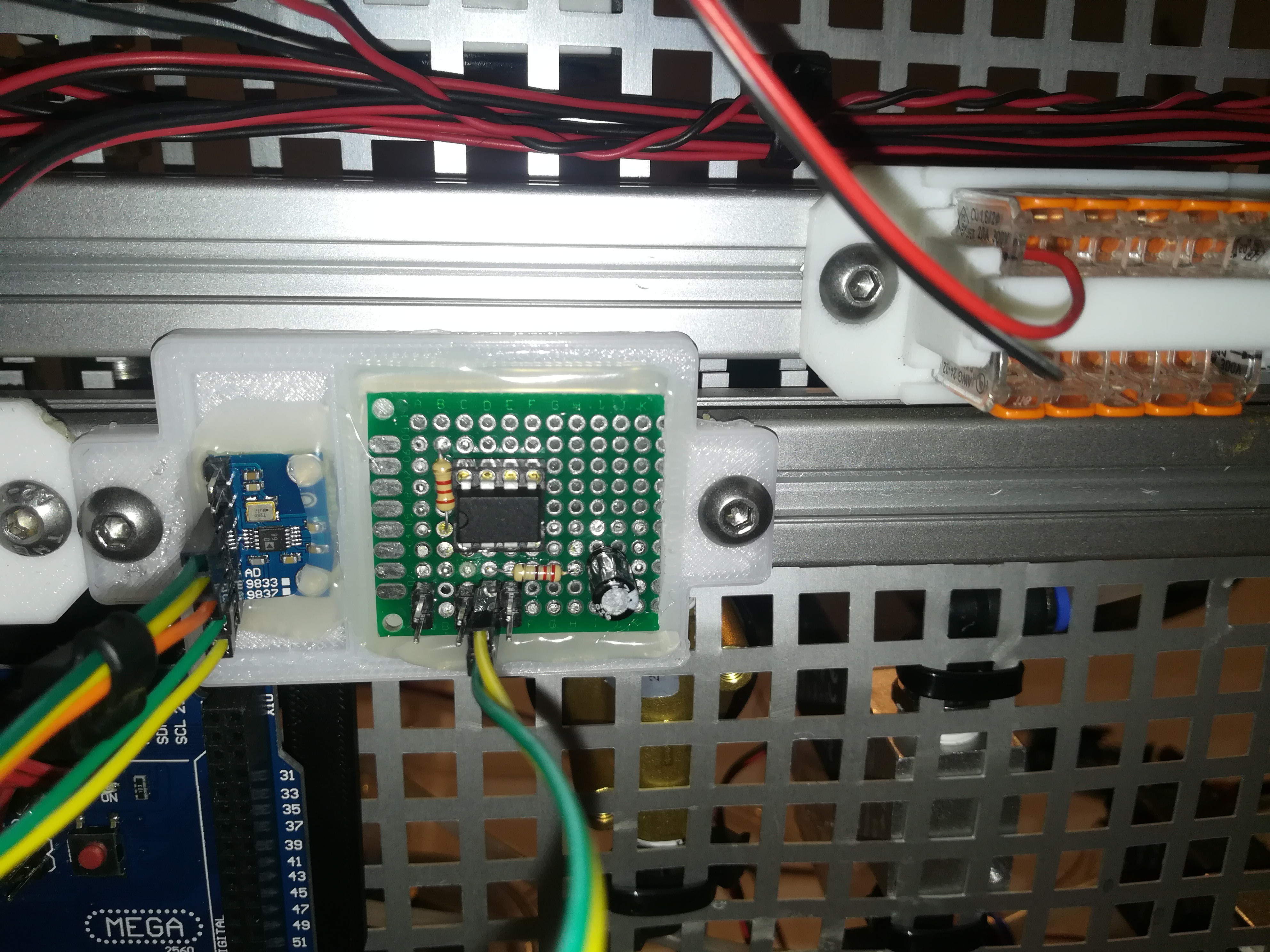
Finally, I mounted the AD9833 + LM393 and also the LM386 amplifier on the printer frame next to the other electronics to keep everything relatively clean.
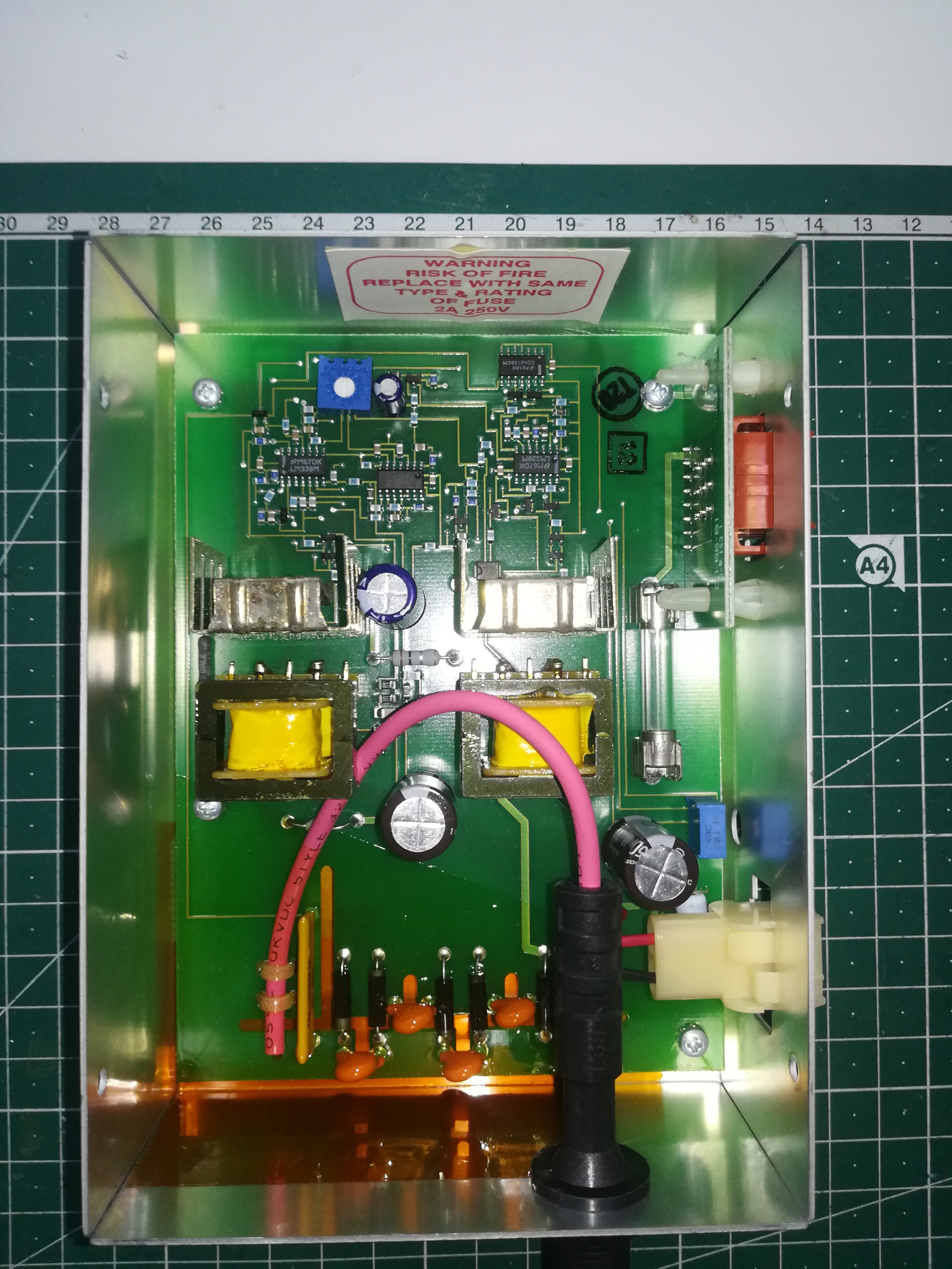
I still have to redesign the printhead to fit the flat piezo disc to the nozzle, but the next thing I want to work on is building a high-voltage power supply, like this one from an old CIJ printer, to power the charging/phasing and deflecting circuit.
Thanks for your interest in my project, until then.
Discussions
Become a Hackaday.io Member
Create an account to leave a comment. Already have an account? Log In.