 Maakbaas
After receiving the circuit boards for my soil moisture sensor, the biggest question was whether the actual sensor would work. It seems like dark magic, how a simple copper pad, connected to an ESP32 without any additional circuitry could turn into a moisture sensor. Therefore, the first thing I did after building the boards is to see how well this would work.
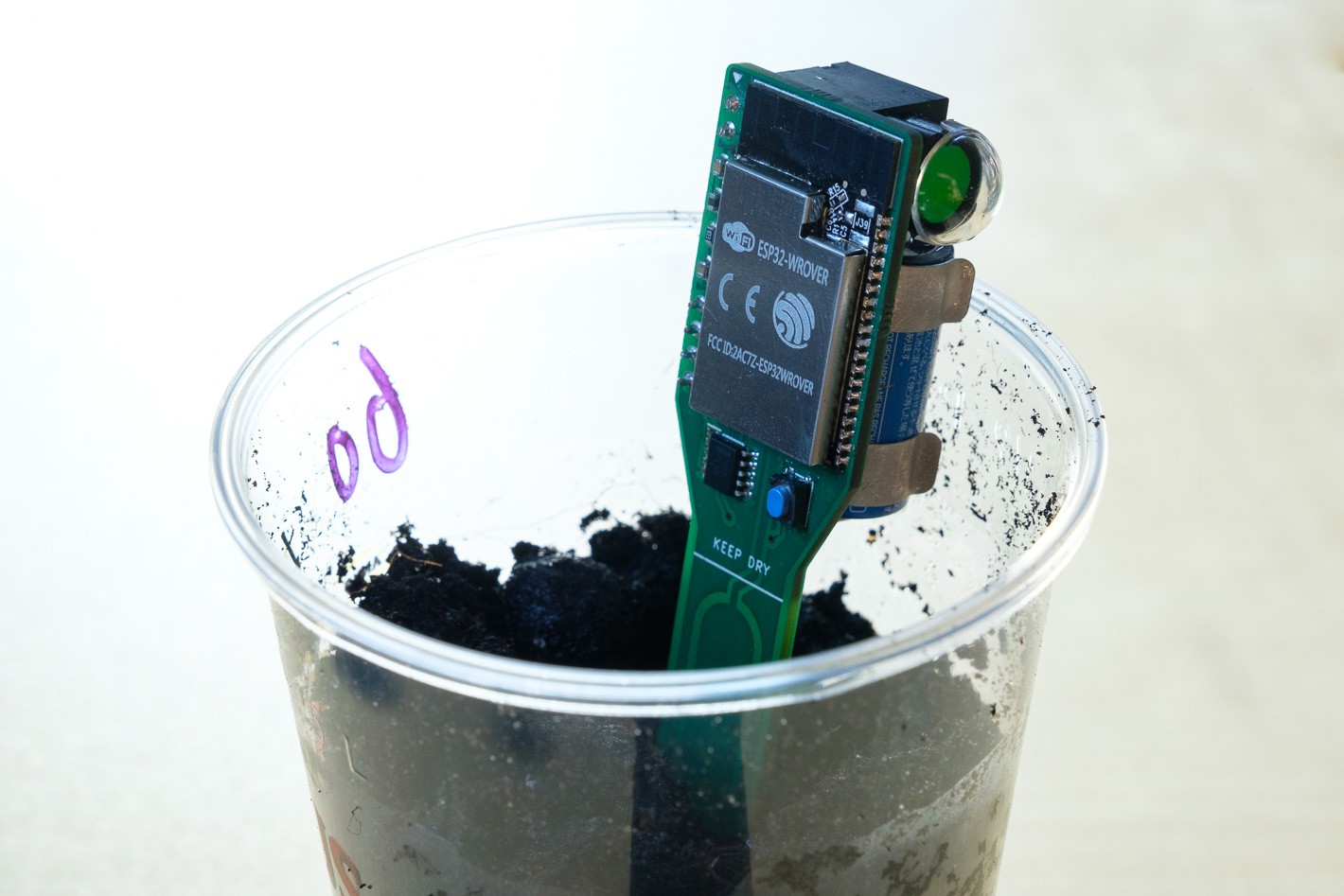
Before diving into that, lets see how the board turned out:
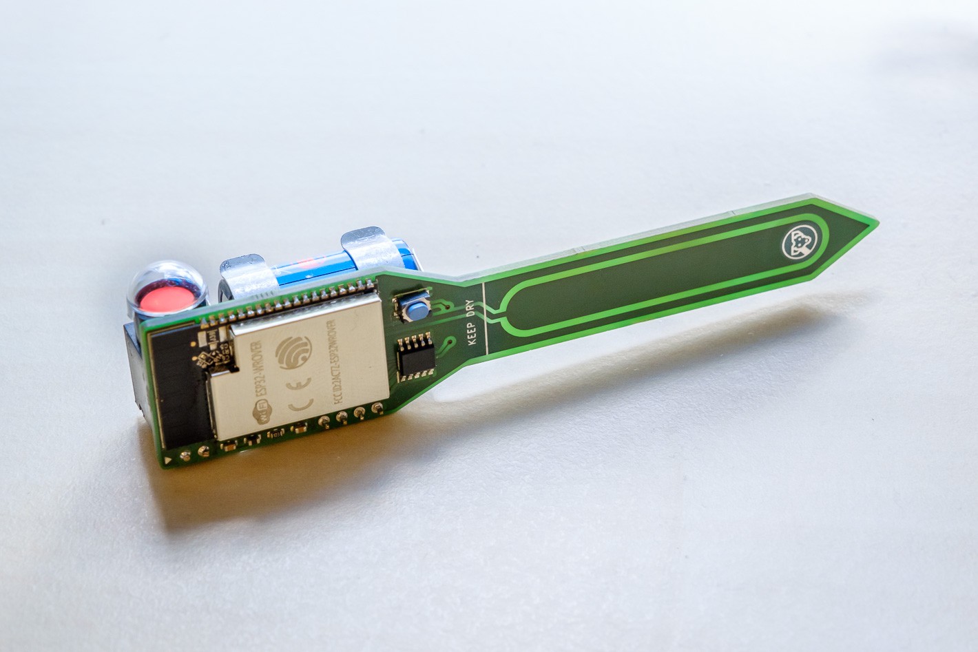
The finished board for the ESP32 soil moisture sensor.
The red dot on the left of the photo is a status indicator. This component can flip between green and red to show if the plant needs water and only uses current when switching between states. Pretty cool if you ask me.
How capacitive measurements work
In order to take away the magic, lets look at how the touch GPIO of the ESP32 actually works, and what is going on behind the scenes. The large copper pad on my PCB has a certain capacitance that (hopefully) changes based on what is around it. Air, water or soil should all lead to a different capacitance of this pad. This is exactly the same for the case of a more typical touch sensor application. Just like water, your finger will increase the self capacitance of the copper pad, allowing the ESP32 to detect this as a touch.
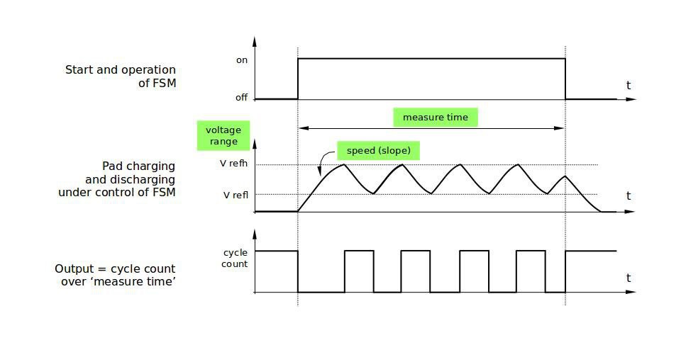
How the ESP32 measures capacitance.
Since capacitance can't be measured directly, the ESP32 uses a trick for this. As can be seen in the figure above, the ESP toggles the output of the touch pin until a certain voltage is reached, after that, the stimulus is removed and the voltage discharges again. The lower the capacitance, the quicker this cycle.
During a predefined period of time, the ESP32 keeps toggling the pad, and the more cycles it can perform during this period, the lower the capacitance. Therefore, what we should see is a decrease in the touch GPIO output when the amount of water increases.
Reading the touch sensor
First I tested the sensor using the touchRead Arduino function. With this I saw an output of around 60 when the sensor was in open air, and close to zero when touching the pad. Success! At least the sensor is doing something! However, 60 as a maximum output was not the granularity I had hoped for. Therefore I switched to using the ESP-IDF functions where more setup is possible:
//one time initialization
touch_pad_init();
touch_pad_set_voltage(TOUCH_HVOLT_2V4, TOUCH_LVOLT_0V5, TOUCH_HVOLT_ATTEN_1V);
touch_pad_config(TOUCH_PAD_NUM2, 0);

//read touch output
uint16_t output;
touch_pad_read(TOUCH_PAD_NUM2,&output);
Serial.println(output);
Initialize and read the touch pad using the ESP-IDF API.
With these functions, the maximum output in open air has increased to around 1000, giving the sensor a much higher sensitivity. With this I started my further testing with actual soil.
Testing and calibration
I created a set of cups with increasing amounts of water and mixed soil into it from dry to very, very wet.
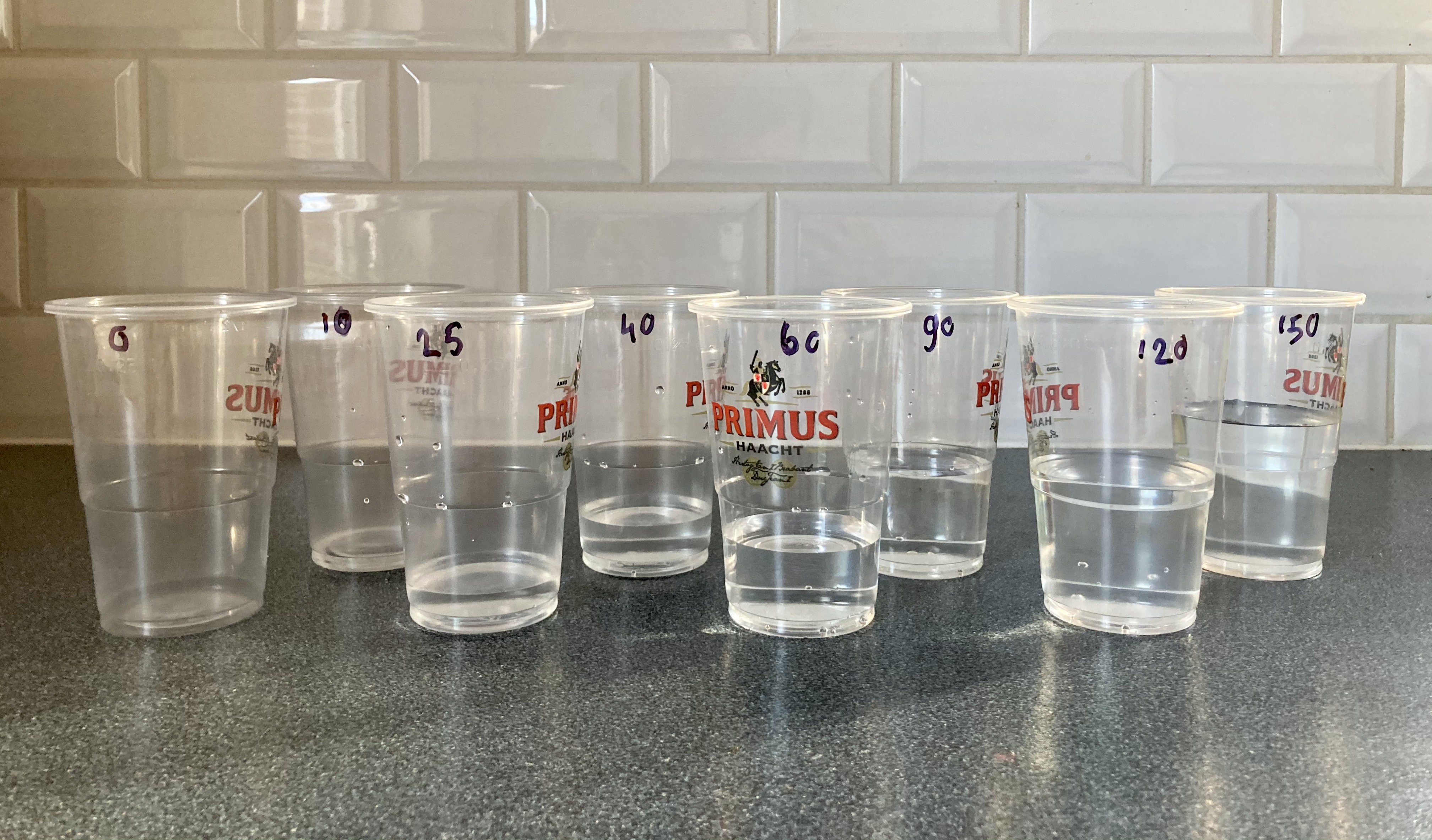
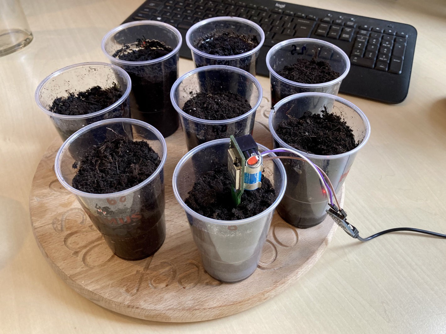
Testing the soil moisture sensor.
The results of this test were promising, but not good enough to be usable.
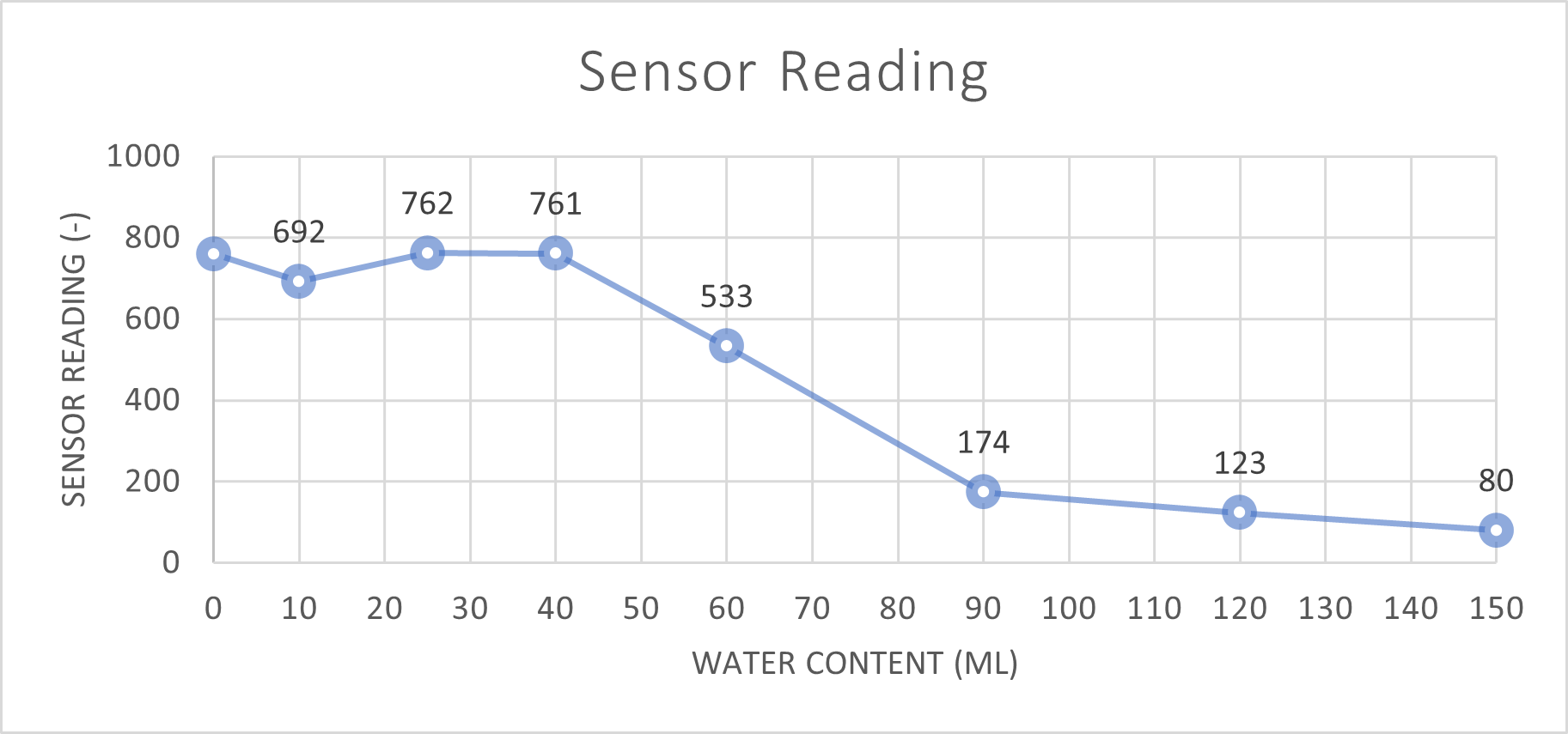
First results
Although this test clearly shows a decreasing capacitance with increasing water content, this is mainly for really wet soil. I asked my wife to fill one of the cups as if she was watering a plant (this goes to show I really need this sensor 😂), and this came out around 40ml. This means that the region between 0 and 40ml is the most important to measure.
There was however a major flaw in my test. I first put the water in the cup, and then the soil. Meaning that for lower water levels, most of the soil was dry, except for a small layer on the bottom, where my sensor did not even reach. After realizing this, I did the test again, but now watering the soil, just like you would do with a plant. I removed the really wet data points from the test, since they were not relevant.
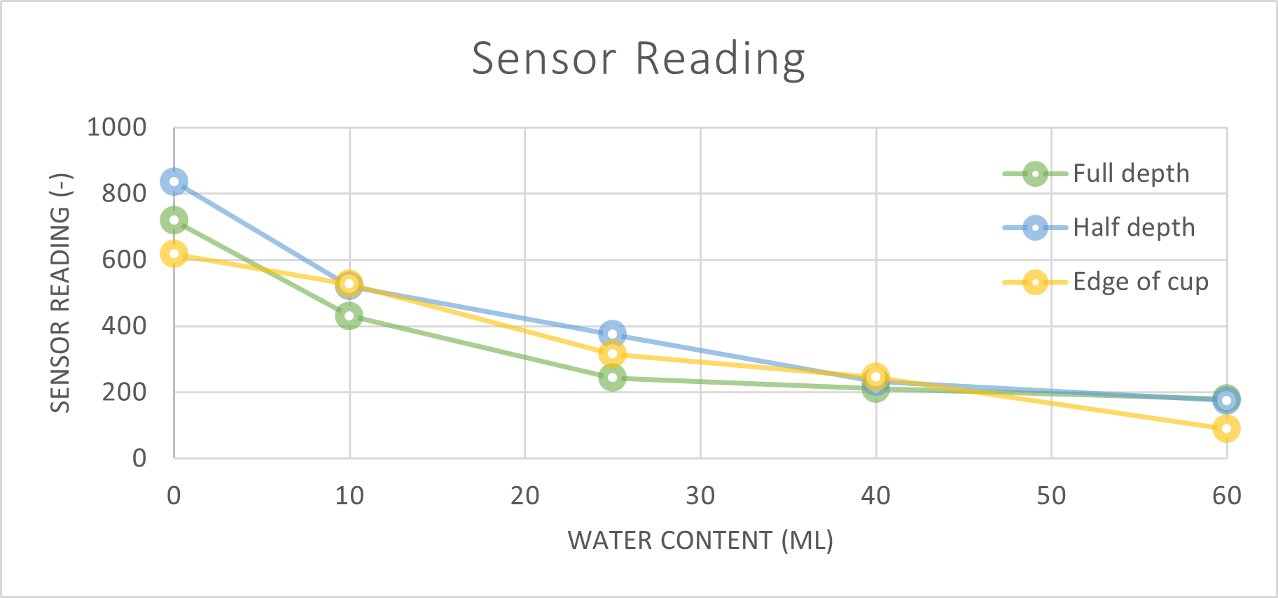
Results for different sensor positions
Luckily with this second test the results at lower moisture levels where much better. It can clearly be seen that the sensor reading decreases for water levels between 0 and 40ml. This means the sensor is definitely usable for its intended purpose!
I also tried placing the sensor at full and half depth, and close to the edge of the cup. As expected, this also causes variation, but the trends remain as it should. What this does mean however is that the threshold for a sensor needs to be set individually for each device. With this sensitivity to sensor placement a real absolute repeatable measurement is not feasible. This was in line with my expectations, which is why I also added a push button to the design that enables user calibration.
Next steps
In the next posts I will first implement deep sleep and all the software for the sensor to work in standalone mode. After that, the connectivity and WiFi functions will be presented.
The soil moisture sensor in action.
Discussions
Become a Hackaday.io Member
Create an account to leave a comment. Already have an account? Log In.