 Michael Gardi
Background
If you have been following Hackaday for a while, you will have seen on numerous occasions the KENBAK-1, regarded by many as the first commercial personal computer. Ten years ago Mark Wilson introduced KENBAK-uino, a reproduction running in emulation on an ATmega328. In 2016 Brian Benchoff posted a great writeup about John Blankenbaker KENBAK-1's creator. For a first hand account of the KENBAK-1 story you should really have a look at John Blakenbaker's own KENBAK-1 Computer site.
For a while you could purchase a full size KENBAK-1 Reproduction Kit, with a PCB, power supply, authentic metal case, 132 standard series TTL logic ICs as the CPU / process control logic (that's right no microprocessor) and two 1024 bit shift registers for memory. Unfortunately this option is no longer available, but based on Mark Wilson's code Adwater & Stir offers a ruler sized nanoKENBAK-1, a half size µKENBAK-1 kit, and will soon be offering a full sized kit as well. In addition you can find KENBAK-1 emulators online like this one.
Motivation
So with all of this rightly deserved KENBAK-1 love out there, why am I creating yet another KENBAK-1 emulator? The flip answer might be that I want to and I can, but that's not all of it. While all of the wonderful reproductions out there emulate the original to a tee and give a true KENBAK-1 experience, and even have some addition features like built in programs, at the end of the day you are still in many cases hand translating machine instructions and keying them in via the front panel buttons one step at a time. And when something goes wrong, while you can step through your program one instruction at a time you only have visibility into one thing at a time on the front panel display, the instruction or a memory/register address. It gets old pretty fast.
Where I think I can add some value is to integrate the machine code Emulator with an Assembler and a Debugger. You will still be able to fire up my KENBAK-2/5 console to key and run your programs in native mode via the front panel. In addition you will be able to open an integrated development environment, enter in a KENBAK-1 program via assembly language and run said program using the actual console. Similarly you will be able to step through your assembly code, set break points, and observe memory and register contents as you do.
My other motivation for this project is that I really wanted to do a deep dive on this machine. When I looked at the Programming Reference Manual I was very impressed with the machine architecture and the instruction set. I mean an Indirect Indexed addressing mode on a machine built with logic chips. So cool.
Design Considerations
- The console itself will be rendered at 2:5 scale (hence the name KENBAK-2/5). This is primarily so that all of the parts will fit onto the print bed of my Prusa MK3S.
- A built in Raspberry Pi 4 will be connected to the front panel via a 32 channel port expander. In addition to running the KENBAK-1 Emulator, the extra horse power of the Pi will be required to run the "integrated development environment" (IDE).
- The IDE will be accessed by connecting a display, keyboard, and mouse to the console's PI 4 itself or via VNC (preferred).
- The Emulator, Assembler, and Debugger will be written in Python.
Hardware Required
In addition to the 3D printed parts you will require the following:
- 1 Raspberry Pi 4
- 1 MCP23017 32 Channel I/O Expansion HAT (https://www.buyapi.ca/product/mcp23017-hat-32-channel-io-expansion-hat/)
- 12 3mm LEDs (8 white and 4 yellow)
- 2 Toggle switches (KINYOOO SPDT Mini Toggle, On/On 3 Pins 2 Position - Amazon)
- 15 Push Button Switches (Mini 7mm Momentary (Off-ON) Push Button - Amazon - 8 black and 7 white)
- Hook up wire. I used 22 AWG.
- Female headers with 2.54 mm spacing.
Making the Console
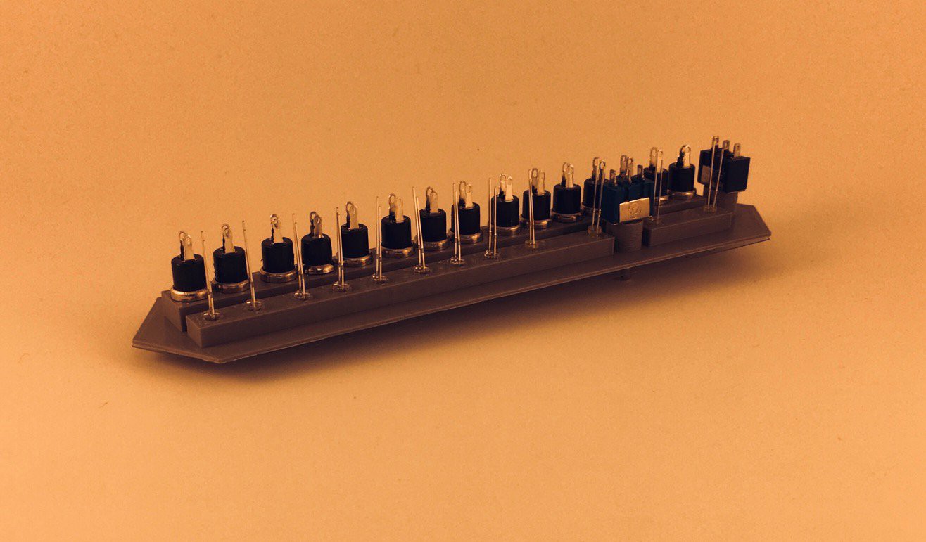
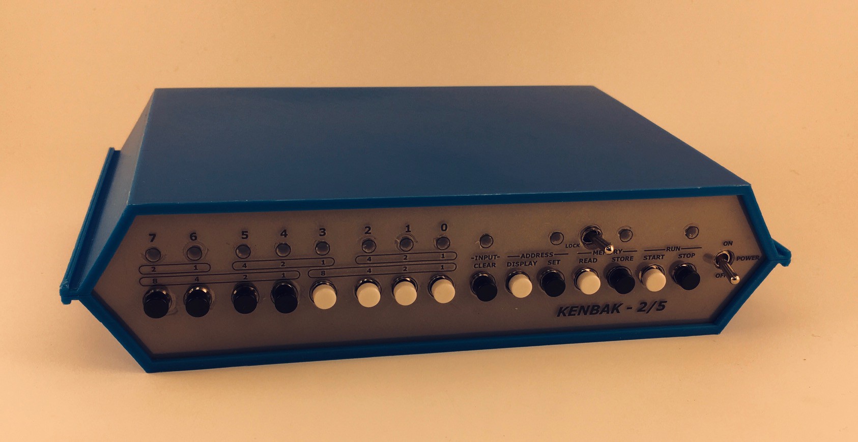
The KENBAL-2/5 console has a 3D printed frame and uses panel mount components. At 40% the size of the original a few compromises had to be made. For one, the great keyboard style push buttons on the front panel of John Blankenbaker's machine proved impossible to replicate. In fact the button positions had to be stretched out horizontally a bit on my reproduction to accommodate the small panel mount push buttons that I did find. Similarly no nice sockets for the panel lamps, just rear mounted 3 mm LEDs.
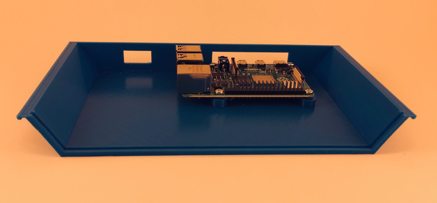
The advantage of the small size is that the pieces will fit on a fairly large selection of 3D printers out there. The shape of the case is a pretty close match to the original as far as I can tell. It is printed in five parts. The bottom has mounting pegs for this project's Raspberry Pi "engine" and cutouts for cabling.
Nothing special about top piece. Notice the groove in both the top and bottom pieces used to hold the front panel in place.

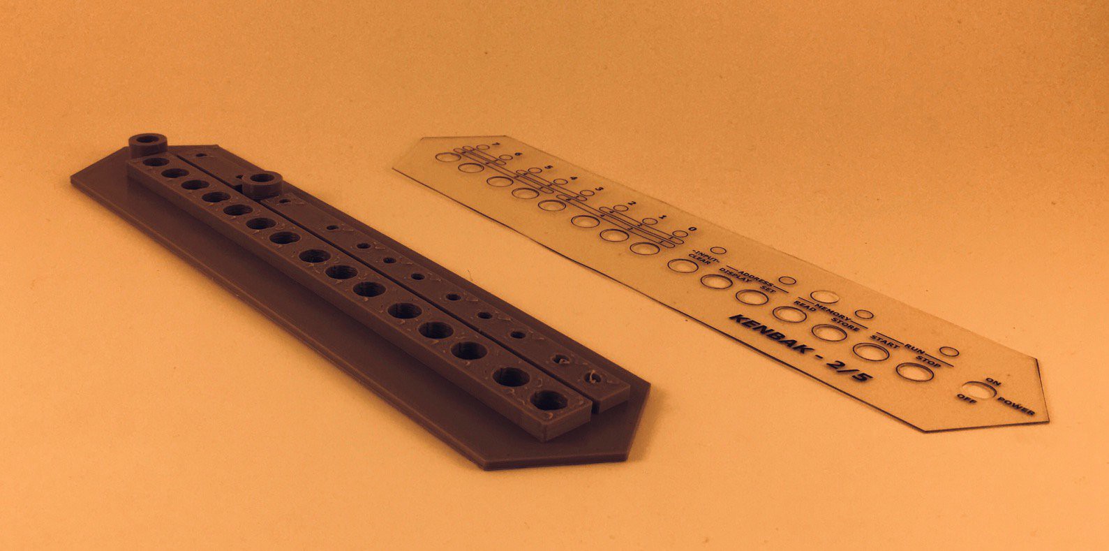
The front panel has holes to hold the buttons, switches, and lights. Because of the small size of the reproduction I was not able to just 3D print the labels directly on the panel as I have in the past with other projects. Instead I saved a DXF file with the panel outline and hole positions from my Fusion 360 model and brought that into Inkscape where I added the labels. I printed the resulting SVG file onto a clear acetate sheet which I laminated to protect the printing and add rigidity to the overlay. I cut the overlay out along the outline and punched the button and switch holes with a standard hand held 1/4" paper punch. The panel lights are recessed behind the overlay so do not require holes.
I could not use the nuts that came with the panel mount buttons and switches because they would not fit at this scale. Instead I sized the holes in the front panel so that the components could be screwed in from the back self threading as they did. The LEDs are just friction fit.
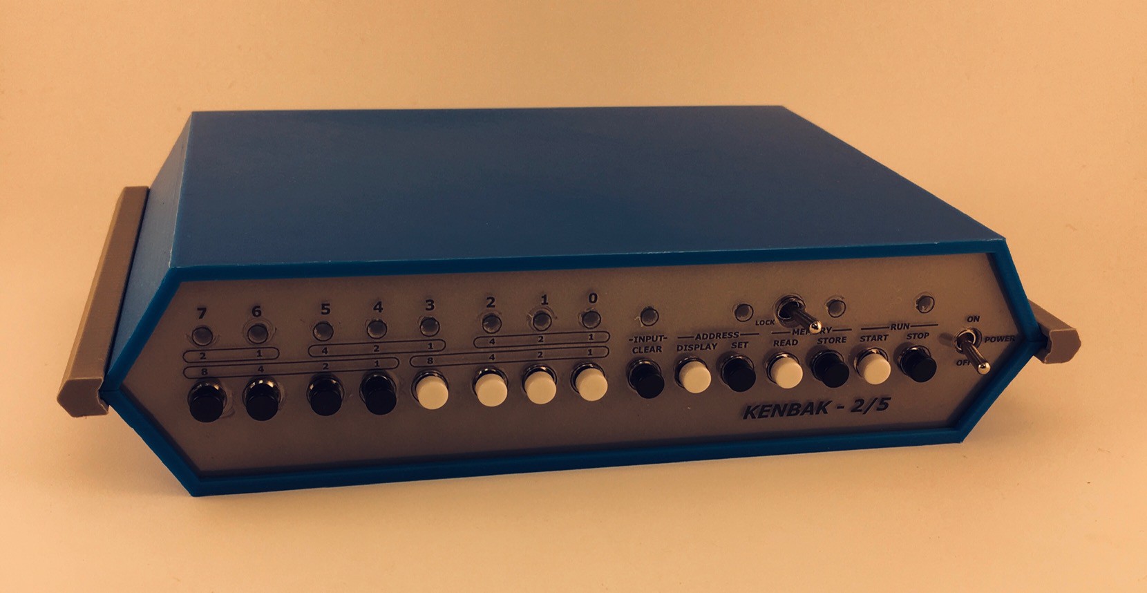
The overlay with the labels will just fit over the buttons and switches with a little finessing.
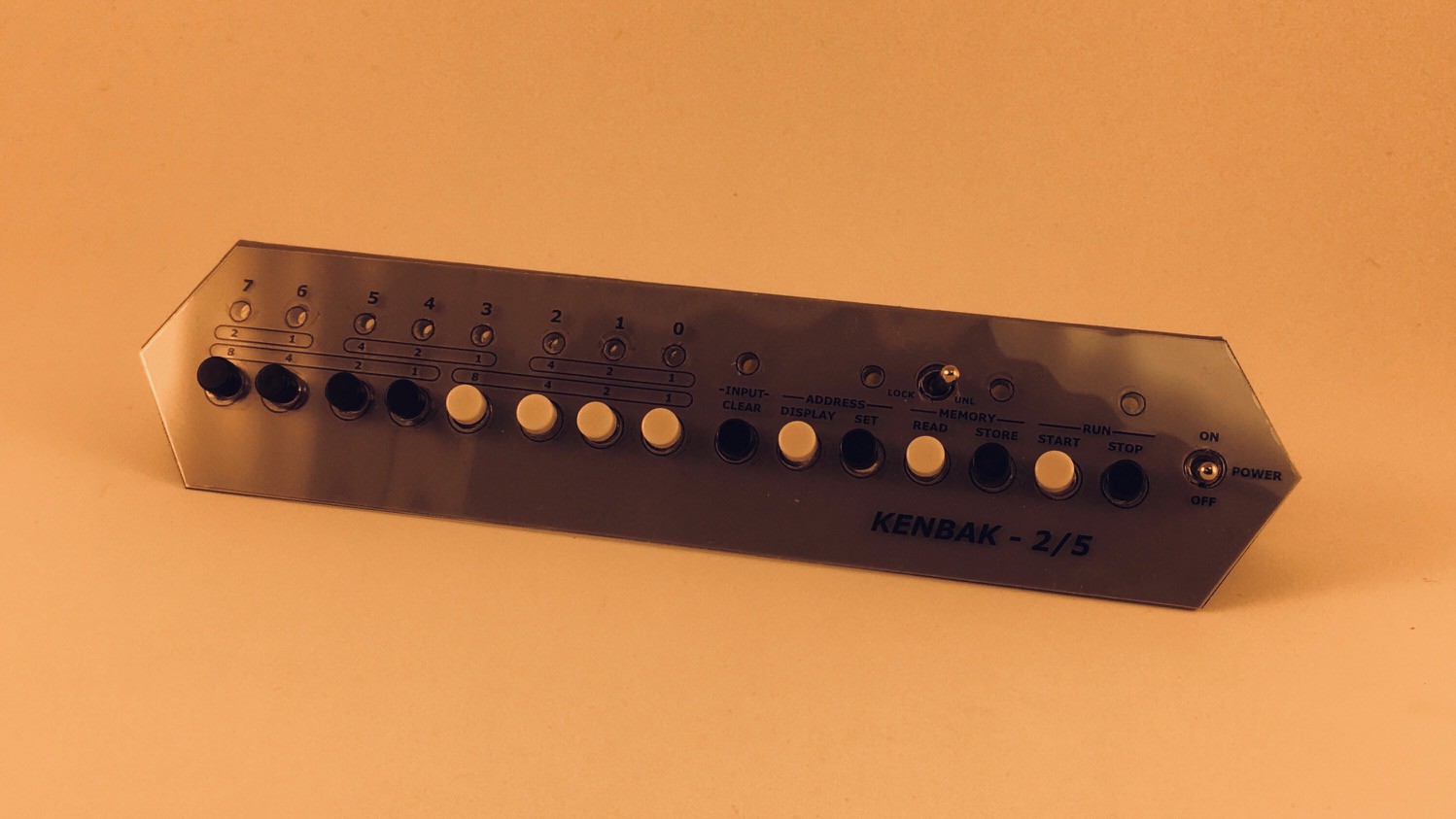
The front panel fits into the grooves cut into the top and bottom pieces.
Join the top and bottom pieces with the slotted side pieces.
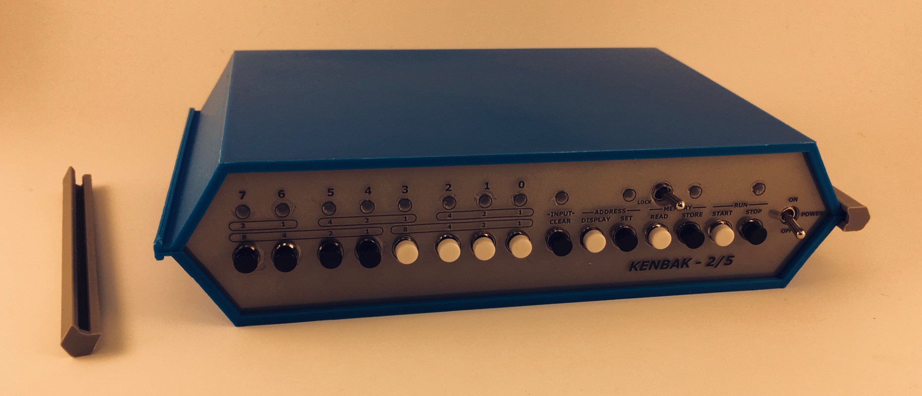
And that's it for the console.
I'm waiting for the port extender hat. When it arrives I'll be wiring the KENBAK-2/5 up. In the mean time I'll be working on the software side.
Writing an Assembler
The KENBAK-1 was intended for the education market. As a result the documentation is excellent. The Programming Reference Manual has all of the information necessary to construct an Assembler for the KENBAK-1 computer:
The Symbolic Representation of Instructions section of the manual gives some guidance as to the abbreviations to be used and the layout for "written" symbolic KENBAK-1 instructions including how to represent the various addressing modes. For the most part I followed those guidelines. I couldn't however bring myself to use NOOP for the no op instruction (I used NOP) and I felt that +X worked better to represent Indexed addressing mode as opposed to ,X. I had a lot of fun trying to come up with a consistent overall look for the instructions.
So in the end I came up with the following document which I feel represents everything I need to provide in a "minimal viable assembler" (MVA) for my KENBAK-2/5 machine.
Assembler Syntax
================

Instructions
~~~~~~~~~~~~
add     [A|B|X],[constant|address]              ;[I|M|(M)|M+X|(M)+X]
sub     [A|B|X],[constant|address]              ;
load    [A|B|X],[constant|address]              ;
store   [A|B|X],[constant|address]              ;
and     [A],[constant|address]                  ;
or      [A],[constant|address]                  ;
lneg    [A],[constant|address]                  ;

jmp     [A|B|X],[NE|EQ|LT|GE|GT|GLE],address    ;[M|(M)]
jmk     [A|B|X],[NE|EQ|LT|GE|GT|GLE],address    ;

skp     [7|6|5|5|4|3|2|1|0],[0|1],address       ;[M]
set     [7|6|5|5|4|3|2|1|0],[0|1],address       ;

sft     [A|B],[L|R],[1|2|3|4]
rot     [A|B],[L|R],[1|2|3|4]

nop
halt

org     constant                                ;[I]

Directives
~~~~~~~~~~
        org     constant                        ;[I]
label   [blank|instruction|constant]            ;[I]
        constant                                ;[I}

The org directive can appear anywhere to set the starting instruction address
for all instructions that follow. If a constant is not present address 4 is
assumed.

If the OpCode position has an Integer Constant, then the value of that constant
is placed at the current address, and the program counter is advanced by one.

Notes
~~~~~

* Any text appearing after a semi-colon (;) on a line will be considered a
  comment and be ignored.

* All OpCodes, operands, and labels are NOT case sensitive.

* A line of assembly code consists of:
    - whitespace (spaces and tabs) OR an optional label followed by whitespace,
    - an OpCode followed by whitespace,
    - optional comma separated operands.

* Labels must start in column 1 and must begin with a letter. A label can stand
  alone on a line or can be followed by an OpCode or an Integer Constant.
  Labels are used to determine a specific instruction address. An offset can be
  added to a label's value when it is used and is defined by appending a + sign
  followed by an Integer Constant, for example label+3.

* For addresses:
   I    - Immediate (Integer Constant)
   M    - Memory
  (M)   - Indirect
  M+X   - Indexed
 (M)+X  - Indirect Indexed

  All of the special memory locations have a reserved address name:

      Name      Address         Usage
      ~~~~      ~~~~~~~         ~~~~~
      A         000             A register.
      B         001             B register.
      X         002             C register.
      PC        003             Program counter.
      OUTPUT    128             Maps to front panel data display lamps.
      OCA       129             Overflow/Carry bits for A register.
      OCB       130             Overflow/Carry bits for B register.
      OCX       131             Overflow/Carry bits for X register.
      INPUT     255             Maps to the front panel data input buttons.

  Any address M beginning with a letter is assumed to be a label associated
  with the actual memory address who's value, obtained using the appropriate
  addressing mode, will be used in the operation. Any address beginning with
  a digit or a dash is assumed to be an Integer Constant representing the
  actual value to be used.

* For jumps:
   NE   - Not equal to zero
   EQ   - Equal to zero
   LT   - Less than zero
   GE   - Greater than or equal to zero
   GT   - Greater than zero
   GLE  - Unconditional (greater or less or equal to zero)

   For an uncoditional jump you can just use the address alone. It's the same
   as using A,GLE,address.

* Integer Constants:
  Decimal - Decimal integers begin with a non-zero digit followed by zero or
            more decimal digits (0–9).
  Octal   - Octal integers begin with zero (0) followed by zero or more octal
            digits (0–7).
  Binary  - Binary integers begin with “0b” or “0B” followed by one or more
            binary digits (0, 1).
  Hex     - Hexadecimal integers begin with “0x” or “0X” followed by one or
            more hexadecimal digits (0–9, A–F). Hexadecimal digits can be
            either uppercase or lowercase.
  Char    - Character values begin with a ' followed by a single character.

  Decimal Integer Constants can have a leading dash (-) to indicate a negative
  number.
I couldn't help but get into the 70's monospaced manual layout documentation vibe.
A Minimum Viable Working Assembler
Still waiting on the port extender hat for my Pi 4, so I had a lot of time to work on the KENBAK-2/5 software. I started with the Assembler based on the outline that I posed in the previous section. It is written in Python using Tkinter for the UI with no external libraries. You can find this early version of the program in the GitHub link associated with this project.
This stand alone Assembler component will eventually be incorporated into a simple IDE for the KENBAK-1.
And a screen shot of the Assembler with a Fibonacci program loaded.
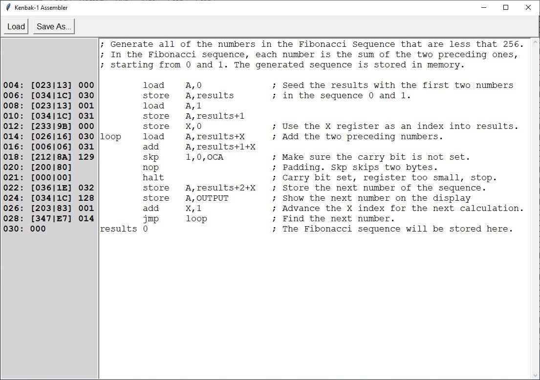
Here we can see:
- constants
- direct and indexed addressing modes
- pre-defined memory locations (OUTPUT, OCA)
- labels and labels with offsets (+1, +2)
With the Assembler done I wrote a number of small programs to exercise the various op codes and addressing modes. These I verified by manually checking the byte codes produced against the documentation in the KENBAK-1 Programming Reference Manual. This is pretty tedious work so I was anxious to get on with the next step, an Emulator.
Is Emulation Really the Sincerest Form of Flattery?
The Emulator for my KENBAK-2/5 Reproduction simulates in software the operation of the 134 integrated circuits that made up the original KENBAK-1's hardware. It accepts as input a 256 byte array that represents the entire block of memory that was in a KENBAK-1 and executes the instructions encoded into those bytes until a HALT instruction is encountered.
While an Assembler takes the symbolic representation of an instruction like LOAD A,1 and converts it into two byte codes 0x13 and 0x01, the emulator recognizes that 0x13 means load the A register with the byte that immediately follows the op code being executed (0x13) and alters the value of the A register to be a 1.
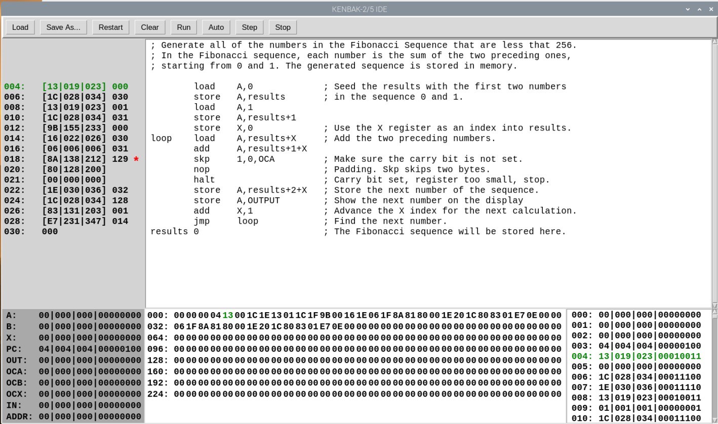
So here is a picture of my KENBAK-2/5 Emulator loaded with the byte codes produced by running my Assembler on the Fibonacci sequence program from the previous log entry. This is an early stand-alone version.
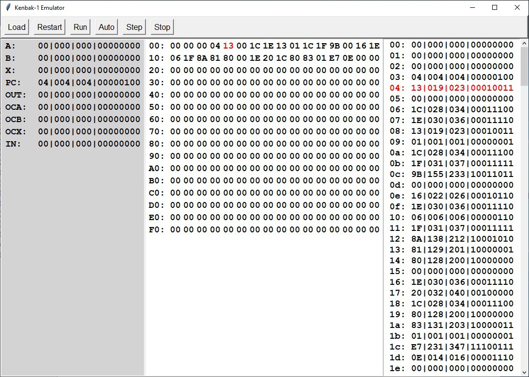
On this screen we can see:
- Left - The values of nine special memory locations in the KENBAK-1:
Name Address Usage A 000 A register. B 001 B register. X 002 X register. PC 003 Program counter. OUT 128 Maps to front panel data display lamps. OCA 129 Overflow/Carry bits for A register. OCB 130 Overflow/Carry bits for B register. OCX 131 Overflow/Carry bits for C register. IN 255 Maps to the front panel data input button - Middle - A hex based overview of the 256 bytes of KENBAK-1 memory.
- Right - A more detailed view of the memory bytes in hex, digital, octal, and binary representations.
Wiring
Well my port extender hat finally arrived so I got busy wiring the front panel to the Raspberry Pi via the extender.
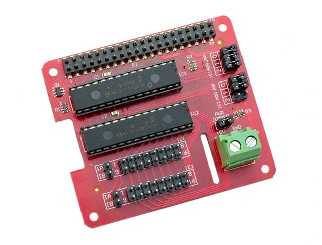
The port extender came with standoffs, so I used two diagonal corner holes on the Raspberry Pi to mount it to the bottom frame, and the opposite two corner holes with the standoffs to support the hat. Seems reasonably solid.
The wiring is as follows with the pin numbers mapping to front panel components:
IC1
- Stop Lamp
- Store Lamp
- Set Lamp
- Clear Lamp
- Toggle Off
- Toggle On
- Toggle Unlock
- Toggle Lock
- Data Lamp 0
- Data Lamp 1
- Data Lamp 2
- Data Lamp 3
- Data Lamp 4
- Data Lamp 5
- Data Lamp 6
- Data Lamp 7
IC2
- Stop Button
- Start Button
- Store Button
- Read Button
- Set Button
- Display Button
- Clear Button
- n/a
- Data Button 0
- Data Button 1
- Data Button 2
- Data Button 3
- Data Button 4
- Data Button 5
- Data Button 6
- Data Button 7
In the following photo I'm about half done. A ground wire has been routed to all of the front panel components, the fifteen push buttons have been connected to the hat, and the twelve LEDs have a short wire with a limiting resistor attached. The resistors are 10k to keep the brightness down.
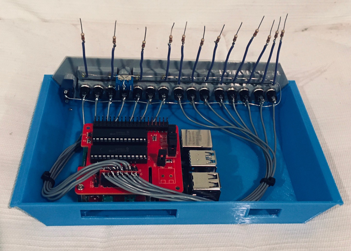
I used female headers to connect the front panel lights and buttons to the extender. Because there wasn't a lot of head room with the top frame on, and limited space between the male headers on the board, I had to angle the wires as in the photo below.
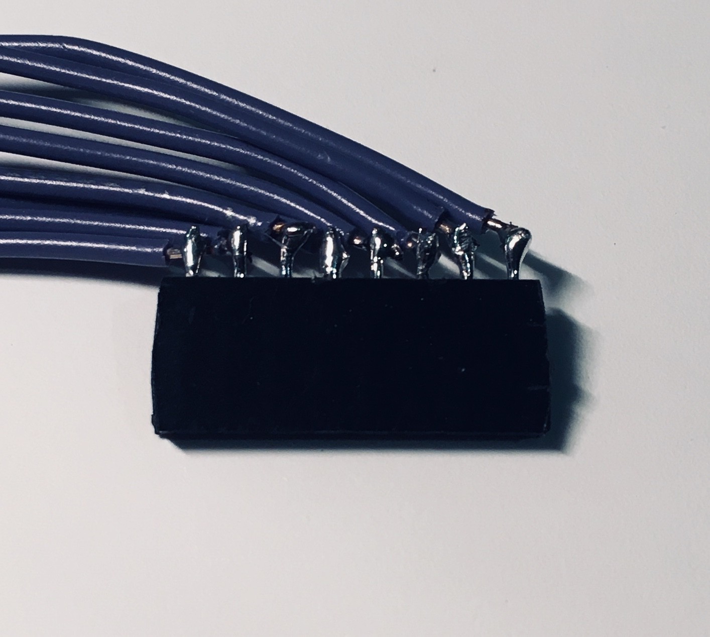
It was a little tight, and as I soldered the wires onto the the header I kept asking myself why I hadn't designed a PCB for the front panel. At the end of the day though it worked out OK.
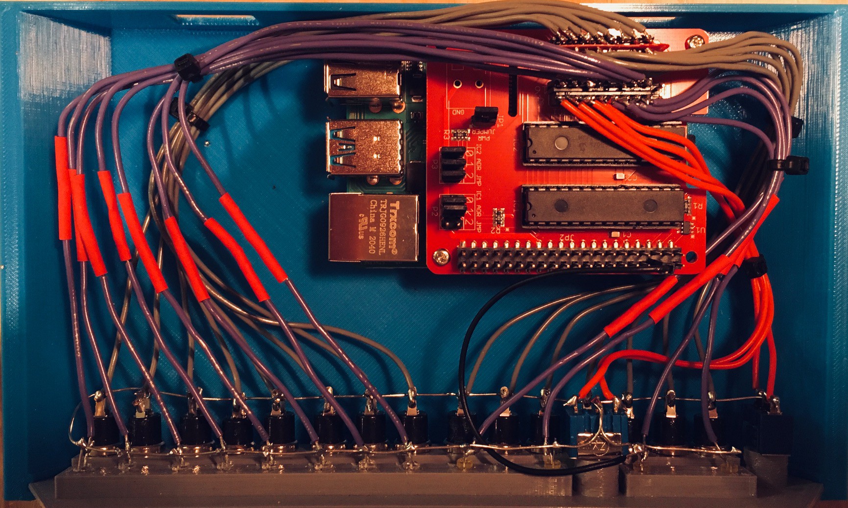
The red heat shrink protects the "inline" limiting resistors for the LEDs. A few cable ties and my KENBAK-2/5 is ready to go.
Next step is to write the code to manage the front panel and integrate it with my Emulator.
We Have Blinkenlights!
With the wiring complete I wrote a small program in Python to test the lights, buttons, and switches on the front panel. To be clear this is NOT the KENBAK-2/5 emulator running a program (yet).
As it turns out I did have to replace one of the LEDs which wasn't working.
The Python script communicates with the MCP23017 32 Channel I/O Expansion HAT through the Python wiringpi library. Here is the code for my test program.
#!/usr/bin/python

import wiringpi as wiringpi
from time import sleep

# Set the base number of ic1.
ic1_pin_base = 65
# Pin number to code number:
# 1 = 65, 2 = 66, 3 = 67, 4 = 68, 5 = 69, 6 = 70, 7 = 71, 8 = 72, 9 = 73, 10 = 74, 11 = 75, 12 = 76, 13 = 77, 14 = 78, 15 = 79, 16 = 80

# Define the i2c address of ic1.
ic1_i2c_addr = 0x24

# Set the base number of ic2.
ic2_pin_base = 81
# Pin number to code number:
# 1 = 81, 2 = 82, 3 = 83, 4 = 84, 5 = 85, 6 = 86, 7 = 87, 8 = 88, 9 = 89, 10 = 90, 11 = 91, 12 = 92, 13 = 93, 14 = 94, 15 = 95, 16 = 96

# Define the i2c address of ic2.
ic2_i2c_addr = 0x20

# Initialize the wiringpi library.
wiringpi.wiringPiSetup()
# enable ic1 on the mcp23017 hat
wiringpi.mcp23017Setup(ic1_pin_base,ic1_i2c_addr)
# enable ic2 on the mcp23017 hat
wiringpi.mcp23017Setup(ic2_pin_base,ic2_i2c_addr)

# Setup led pins.
light_stop = 65
light_store = 66
light_set = 67
light_clear = 68

light_0 = 73
light_1 = 74
light_2 = 75
light_3 = 76
light_4 = 77
light_5 = 78
light_6 = 79
light_7 = 80

# Setup toggle pins.
toggle_off = 69
toggle_on = 70
toggle_unl = 71
toggle_lock = 72

# Setup button pins
button_stop = 81
button_start = 82
button_store = 83
button_read = 84
button_set = 85
button_display = 86
button_clear = 87
button_0 = 89
button_1 = 90
button_2 = 91
button_3 = 92
button_4 = 93
button_5 = 94
button_6 = 95
button_7 = 96

# Set the pin mode to an output for all the leds.
wiringpi.pinMode(light_stop,1)
wiringpi.pinMode(light_store,1)
wiringpi.pinMode(light_set,1)
wiringpi.pinMode(light_clear,1)
wiringpi.pinMode(light_0,1)
wiringpi.pinMode(light_1,1)
wiringpi.pinMode(light_2,1)
wiringpi.pinMode(light_3,1)
wiringpi.pinMode(light_4,1)
wiringpi.pinMode(light_5,1)
wiringpi.pinMode(light_6,1)
wiringpi.pinMode(light_7,1)

# Set all the leds off to start with.
wiringpi.digitalWrite(light_stop,0)
wiringpi.digitalWrite(light_store,0)
wiringpi.digitalWrite(light_set,0)
wiringpi.digitalWrite(light_clear,0)
wiringpi.digitalWrite(light_0,0)
wiringpi.digitalWrite(light_1,0)
wiringpi.digitalWrite(light_2,0)
wiringpi.digitalWrite(light_3,0)
wiringpi.digitalWrite(light_4,0)
wiringpi.digitalWrite(light_5,0)
wiringpi.digitalWrite(light_6,0)
wiringpi.digitalWrite(light_7,0)


# Set the pin mode to an input for all the switches and buttons.
wiringpi.pinMode(toggle_off,0)
wiringpi.pinMode(toggle_on,0)
wiringpi.pinMode(toggle_lock,0)
wiringpi.pinMode(toggle_unl,0)

wiringpi.pinMode(button_stop,0)
wiringpi.pinMode(button_start,0)
wiringpi.pinMode(button_store,0)
wiringpi.pinMode(button_read,0)
wiringpi.pinMode(button_set,0)
wiringpi.pinMode(button_display,0)
wiringpi.pinMode(button_clear,0)
wiringpi.pinMode(button_0,0)
wiringpi.pinMode(button_1,0)
wiringpi.pinMode(button_2,0)
wiringpi.pinMode(button_3,0)
wiringpi.pinMode(button_4,0)
wiringpi.pinMode(button_5,0)
wiringpi.pinMode(button_6,0)
wiringpi.pinMode(button_7,0)

# Enable the internal pull-ups on all the inputs
wiringpi.pullUpDnControl(toggle_off,2)
wiringpi.pullUpDnControl(toggle_on,2)
wiringpi.pullUpDnControl(toggle_lock,2)
wiringpi.pullUpDnControl(toggle_unl,2)

wiringpi.pullUpDnControl(button_stop,2)
wiringpi.pullUpDnControl(button_start,2)
wiringpi.pullUpDnControl(button_store,2)
wiringpi.pullUpDnControl(button_read,2)
wiringpi.pullUpDnControl(button_set,2)
wiringpi.pullUpDnControl(button_display,2)
wiringpi.pullUpDnControl(button_clear,2)
wiringpi.pullUpDnControl(button_0,2)
wiringpi.pullUpDnControl(button_1,2)
wiringpi.pullUpDnControl(button_2,2)
wiringpi.pullUpDnControl(button_3,2)
wiringpi.pullUpDnControl(button_4,2)
wiringpi.pullUpDnControl(button_5,2)
wiringpi.pullUpDnControl(button_6,2)
wiringpi.pullUpDnControl(button_7,2)

# Test
step = 0
while True:    # Check for button presses.    if not wiringpi.digitalRead(button_0):        wiringpi.digitalWrite(light_0,1)    else:        wiringpi.digitalWrite(light_0,0)            if not wiringpi.digitalRead(button_1):        wiringpi.digitalWrite(light_1,1)    else:        wiringpi.digitalWrite(light_1,0)        if not wiringpi.digitalRead(button_2):        wiringpi.digitalWrite(light_2,1)    else:        wiringpi.digitalWrite(light_2,0)            if not wiringpi.digitalRead(button_3):        wiringpi.digitalWrite(light_3,1)    else:        wiringpi.digitalWrite(light_3,0)        if not wiringpi.digitalRead(button_4):        wiringpi.digitalWrite(light_4,1)    else:        wiringpi.digitalWrite(light_4,0)           if not wiringpi.digitalRead(button_5):        wiringpi.digitalWrite(light_5,1)    else:        wiringpi.digitalWrite(light_5,0)            if not wiringpi.digitalRead(button_6):        wiringpi.digitalWrite(light_6,1)    else:        wiringpi.digitalWrite(light_6,0)        if not wiringpi.digitalRead(button_7):        wiringpi.digitalWrite(light_7,1)    else:        wiringpi.digitalWrite(light_7,0)            if not wiringpi.digitalRead(button_stop):        wiringpi.digitalWrite(light_stop,1)    else:        wiringpi.digitalWrite(light_stop,0)        if not wiringpi.digitalRead(button_start):        wiringpi.digitalWrite(light_stop,1)    else:        wiringpi.digitalWrite(light_stop,0)            if not wiringpi.digitalRead(button_store):        wiringpi.digitalWrite(light_store,1)    else:        wiringpi.digitalWrite(light_store,0)        if not wiringpi.digitalRead(button_read):        wiringpi.digitalWrite(light_store,1)    else:        wiringpi.digitalWrite(light_store,0)            if not wiringpi.digitalRead(button_set):        wiringpi.digitalWrite(light_set,1)    else:        wiringpi.digitalWrite(light_set,0)        if not wiringpi.digitalRead(button_display):        wiringpi.digitalWrite(light_set,1)    else:        wiringpi.digitalWrite(light_set,0)            if not wiringpi.digitalRead(button_clear):        wiringpi.digitalWrite(light_clear,1)    else:        wiringpi.digitalWrite(light_clear,0)            if not wiringpi.digitalRead(toggle_on):        wiringpi.digitalWrite(light_clear,1)    else:        wiringpi.digitalWrite(light_clear,0)        if not wiringpi.digitalRead(toggle_off):        wiringpi.digitalWrite(light_set,1)    else:        wiringpi.digitalWrite(light_set,0)            if not wiringpi.digitalRead(toggle_lock):        wiringpi.digitalWrite(light_store,1)    else:        wiringpi.digitalWrite(light_store,0)            if not wiringpi.digitalRead(toggle_unl):        wiringpi.digitalWrite(light_stop,1)    else:        wiringpi.digitalWrite(light_stop,0)            if step == 0:        wiringpi.digitalWrite(light_7,0)        wiringpi.digitalWrite(light_0,1)    elif step == 1:        wiringpi.digitalWrite(light_0,0)        wiringpi.digitalWrite(light_1,1)    elif step == 2:        wiringpi.digitalWrite(light_1,0)        wiringpi.digitalWrite(light_2,1)    elif step == 3:        wiringpi.digitalWrite(light_2,0)        wiringpi.digitalWrite(light_3,1)    elif step == 4:        wiringpi.digitalWrite(light_3,0)        wiringpi.digitalWrite(light_4,1)    elif step == 5:        wiringpi.digitalWrite(light_4,0)        wiringpi.digitalWrite(light_5,1)    elif step == 6:        wiringpi.digitalWrite(light_5,0)        wiringpi.digitalWrite(light_6,1)    elif step == 7:        wiringpi.digitalWrite(light_6,0)        wiringpi.digitalWrite(light_7,1)    step = (step + 1) % 8            # Wait a bit.    sleep(.2)
Sometimes I miss the bad old days where new things seldom worked on the first try and you really had to slog for it, but as is more often than not the case these days everything worked as expected out of the gate (for the exception of the one bad LED).
I'm running Eclipse with PyDev for development on my Windows machine using the Remote Systems feature of Eclipse to save the target .py scripts on the Raspberry Pi 4. From there I simply run the programs on the Pi via SSH or VNC.
Bringing It All Together
I have integrated the Console functionality (being able to read the buttons and show the lamps ) with the Emulator. With just this in place I now have a fully functional KENBAK-1. I can load and run programs and view memory locations from the front panel as described in the Programming Reference Manual and Laboratory Exercises.
But that's not all I wanted to accomplish. With the further integration of my KENBAK-1 Assembler, the IDE that I had envisioned for this project has really taking shape.
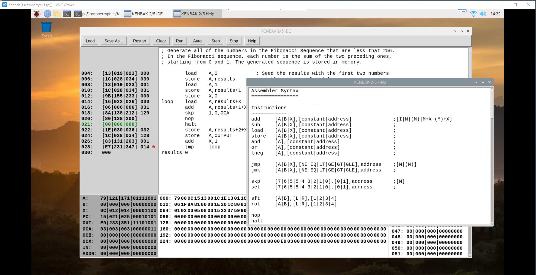
I'm running the Raspberry Pi 4 inside my reproduction headless, but when I VNC into it, this is what I see.
Here I have just loaded the Fibonacci program seen a previous section. The upper right quadrant is of course the assembler code and to it's left the equivalent binary instructions. By clicking on the binary instructions you can set or clear breakpoints (the skp instruction has a breakpoint set for instance).
To the lower left is the state of the predefined "registers" including the address register which is used to load and read memory locations. Middle bottom is a hex dump of all 256 memory locations, and lower right shows the same memory locations in more detail with hex, decimal, octal and binary representations for each location. All references to memory locations are in decimal (leftmost columns in the instruction, hex dump, and details panels and rightmost column in the instruction panel).
The entries rendered in green represent the memory location currently pointed to by the program counter (PC).
The front panel console is fully integrated with the IDE. So for instance you could start the Fibonacci program shown above by pressing the physical START button on the console or by clicking the Run button in the IDE. Similarly pressing and holding the STOP button and then pressing START will perform a single step as will the IDE's Step button.
Anything written to the OUTPUT register will show up on the data lamps on the console. Data stored from the console to memory locations through the address register will be reflected in the IDE.
The IDE does offer some additional features. Your programs can be saved and loaded to disk (the assembler code and the binary memory image both). The Restart button will reset everything to the last loaded image. Clear will zero out memory and the assembler program space then set the PC to memory location 4. Auto will run the program at a rate of about one instruction per second.
You can debug your program by single stepping or by setting breakpoints and observing the memory and registers.
If you just want to play around with KENBAK-1 code, you can run the IDE "standalone" on any platform that supports Python, but of course you will only be able to integrate the KENBAK-2/5 console on a Raspberry Pi since it's bound to the wiringpi library.
Running the KENBAK-1 IDE
The KENBAK-IDE.py file is available from my GitHub repository. If used outside of the KENBAK-2/5 hardware environment, it should run on any machine that supports Python3 without any library dependencies. In this mode you can still write, debug, and run KENBAK-1 assembly language programs. It's a great learning environment all by itself.
If you are running on the KENBAK-2/5's Raspberry Pi with the port extender hat you will have to first make sure that the wiringpi library is installed.
pip3 install wiringpi
I created a folder on the Pi
mkdir /home/pi/KENBAK-1
and copied the KENBAK-IDE.py, Assembler Syntax.txt, Fibonacci.asm, and Fibonacci.bin files there. Then its a simple matter of running the Python script.
cd /home/pi/KENBAK-1
python3 KENBAK-IDE.py
Auto Start the KENBAK-1 IDE
If you are running KENBAK-1 IDE as a dedicated console on the built-in Raspberry Pi like I am it's convenient to have the program start automatically when the machine boots. Here is what I did to make this happen.
I created an autostart folder on my Pi and switched to that folder.
mkdir /home/pi/.config/autostart
cd /home/pi/.config/autostart
Into the autostart folder just created I added the following two files.
runKENBAK-1
cd /home/pi/KENBAK-1
/usr/bin/python3 KENBAK-IDE.py
KENBAK-1.desktop
[Desktop Entry]
Type=Application Name=KENBAK-1
Exec=/home/pi/.config/autostart/runKENBAK-1
In addition the runKENBAK-1 file must be made executable with the following command:
chmod 777 runKENBAK-1
Now if you reboot the system, you should briefly see the desktop appear, and shortly after KENBAK-IDE application will load.
Setting up VNC
Current Raspberry Pi OS versions have RealVNC baked in. If you are running the Raspberry Pi in the KENBAK-2/5 console headless as I am you have to setup a virtual desktop for the VNC client to connect to. The easiest way I have found to do this is to add the following lines to the end of the /etc/rc.local file before the exit 0 on the Pi.
# Setup a virtual screen for the VNC server.
sudo -u pi vncserver -randr=1920x1080
Set the screen dimension to be the same as the machine that you will be accessing the KENBAK-IDE from. You should then be able to connect to the KENBAK-2/5 with a RealVNC client at the machines IP address with a :1 appended, for example in my case 192.168.123.122:1.
Finishing Up
I did some additional testing of the IDE and added a Help button to popup some information on the assembly syntax.
I made a video where I try to demonstrate how the KENBAK-2/5, with it's built in Raspberry Pi, does a good job as a KENBAK-1 reproduction. As with the original you can enter and run programs, and view internal machine memory, just using the switches, buttons, and lamps on the front panel of the console.
But in addition, using the power of the Raspberry Pi 4 to implement an Integrated Development Environment, you can key in programs using native KENBAK-1 assembly language. As can be seen in the video, the Assembler has no "passes". The assembler instructions are continuously parsed as you type and when the corresponding binary code no longer has any question marks you know the syntax for the line is correct. It all works quite well.
With breakpoints, single step modes, and memory visualizations, debugging suddenly becomes a lot easier.
When I first looked at the KENBAK-1 Programming Reference Manual I was very impressed with the instruction set for a machine with no microprocessor, just discrete logic chips. Implementing an Assembler and Emulator only served to deepen my appreciation for what John Blankenbaker created. It was quite an achievement for its time and John Blankenbaker deserves his place in history as an early personal computer pioneer.
One More Thing
When John Blankenbaker was demonstrating his KENBAK-1 Personal Computer back in 1971, one of the programs he always showed was a Day of the Week calculator. Given any date, it can tell you what day of the week that date fell on. It was something that was pretty cool that everyone could relate to.
Well I didn't feel that my KENBAK-2/5 reproduction would be quite complete until it could do the same. It was a fun programming challenge that exercised a lot more of the capabilities of my machine, and in fact uncovered a few minor issues with my emulator software:
- JMK operand was not saving the return address correctly
- HALT operand needed to advance the program counter (PC)
- I tweaked some of the console interactions.
- I added a DB directive to reserve a byte of memory.
I feel a lot more confident now that my reproduction is a very close work-a-like to the original. Here is the code:
; Program to calculate the day of the week for any date. To start this program you will
; have to input the date in four parts: Century, Year, Month, and Day. Each of the parts
; is entered as a two digit Binary Coded Decimal number (ie. the first digit will occupy ; bits 7-4 as a binary number, and the second digit bits 3-0) using the front panel data
; buttons. The steps to run this program are:
;
; 1) Set the PC register (at address 3) to 4.
; 2) Clear the input data then enter the date Century.
; 3) Press Start.
; 4) Clear the input data then enter the date Year.
; 5) Press Start.
; 6) Clear the input data then enter the date Month.
; 7) Press Start.
; 8) Clear the input data then enter the date Day.
; 9) Press Start.
;
; The day of the week will be returned via the data lamps using the following encoding:
; ;      7-Sunday 6-Monday 5-Tuesday 4-Wednesday 3-Thursday 2-Friday 1-Saturday
;
; All lamps turned on means the last item entered was invalid and you have to restart.
;
;
; Get the date we want the day for.
;
    load    A,INPUT            ; Get the century.
    jmk    bcd2bin
    store     A,century
    halt
    load    A,INPUT            ; Get the year.
    jmk    bcd2bin
    store    A,year
    halt
    load    A,INPUT            ; Get the month.
    jmk    bcd2bin
    sub    A,1            ; Convert from 1 based to 0 based.
    store    A,month
    halt
    load    A,INPUT            ; Get the day.
    jmk    bcd2bin
    store    A,day
    load    A,0b10000000        ; Setup the rotation pattern.
    store    A,rotate
;
; All the inputs should be in place. Start the conversion.
;
    load     A,year            ; Get the year.
    sft    A,R,2            ; Divide by 4.
    store    A,B            ; Save to B the working result.
    add    B,day            ; Add the day of the month.
    load    X,month            ; Use X as index into the month keys.
    add    B,monkeys+X        ; Add the month key.
    jmk    leapyr            ; Returns a leap year offset in A if applicable.
    jmk    working            ; Working...
    sub    B,A            ; Subtract the leap year offset.
    jmk     cencode            ; Returns a century code in A if applicable.
    jmk    working            ; Working...
    add     B,A            ; Add the century code.
    add    B,Year            ; Add the year input to the working result.
chkrem    load    A,B            ; Find the remainder when B is divided by 7.
    and    A,0b11111000        ; Is B > 7?
    jmp    A,EQ,isseven        ; No then B is 7 or less.
    sub    B,7            ; Yes then reduce B by 7.
    jmk    working            ; Working...
    jmp    chkrem            ; Check again for remainder.
isseven load        A,B        ; Is B = 7?
    sub    A,7            ; Subtract 7 from B value.
    jmp    A,LT,gotday        ; No B is less than 7.
    load    B,0            ; Set B to zero because evenly divisible.
gotday    load    X,B            ; B holds the resulting day number.    Use as index.
    load    A,sat+X            ; Convert to a day lamp.
    store    A,OUTPUT
    halt
error    load    A,0xff            ; Exit with error
    store    A,OUTPUT        ; All lamps lit.
    halt

;
; Store inputs.
;
century db
year    db
month    db
day    db

;
; Static table to hold month keys.
;
monkeys    1
    4
    4
    0
    2
    5
    0
    3
    6
    1
    4
    6

;
; Need to preserve A while performing some steps.
;
saveA    db

;
; Subroutine to blink the lamps to indicate working.
; rotate    db                ; Pattern to rotate.
working    db                ; Save space for return adderess.
    store    A,saveA            ; Remember the value in A.
    load    A,rotate        ; Get the rotate pattern.
    store    A,OUTPUT        ; Show the rotated pattern.
    rot    A,R,1            ; Rotate the pattern.
    store   A,rotate        ; Save the new rotation.
    load    A,saveA            ; Restore the value of A.
    jmp    (working)        ; Return to caller.

    org    133            ; Skip over registers.

;
; Subroutine takes a BCD nuber in A as input and returns the equivalent binary number ; also in A.
;
bcd2bin db                ; Save space for return address.
    store    A,X             ; Save A.
    sft     A,R,4            ; Get the 10's digit.
    jmk    chkdig            ; Make sure digit is 0 - 9.
    store    A,B            ; B will hold the 10's digit x 10 result
    add    B,B            ; B now X 2
    sft    A,L,3            ; A is now 10's digit X 8
    add    B,A            ; B now 10's digit X 10
    store     X,A            ; Retrieve original value of A
    and    A,0b00001111        ; Get the 1's digit value in binary.
    jmk    chkdig            ; Make sure digit is 0 - 9.
    add    A,B            ; Add the 10's digit value in binary.
    jmp    (bcd2bin)        ; A now has the converted BCD value.

;
; Subroutine determines if the date is a leap year in January or February and returns
; an offset of 1 if it is, and 0 otherwise.
;
leapyr  db                ; Save space for return address.
    load     A,month            ; Check to see if month is January or February.
    and    A,0b11111110        ; Are any bits other than bit 0 set?
    jmp    A,NE,notlpyr        ; Yes then not January or February. Return 0.
    load    A,year            ; Is this an even century?
    jmp    A,NE,chkyear        ; No then have to check the year.
    load    A,century        ; Yes so see if century evenly divisible by 4.
    and    A,0b00000011        ; Are bits 1 or 0 set?
    jmp    A,EQ,islpyr        ; Yes evenly divisible by 4 and is a leap year.
    jmp    notlpyr            ; No this is not a leap year.
chkyear load        A,year        ; See if rear evenly divisible by 4.
    and    A,0b00000011        ; Are bits 1 or 0 set?
    jmp    A,NE,notlpyr        ; Yes so not evenly divisible by 4 and not a leap year.
islpyr  load        A,1        ; Offset 1.
    jmp    (leapyr)        ; Return offset.
notlpyr    load    A,0            ; Offset 0.
    jmp    (leapyr)        ; Return offset.

;
; Subroutine determines if a century code needs to be applied to the calculation.
;
cencode db                ; Save space for return address.
    load    A,century        ; Century must be between 17 - 20.
chkmin    sub    A,17            ; Is century less than 17?
    jmp    A,GE,chkmax        ; Yes so century >= 17. Check max boundry.
    load    A,century        ; Increase century by 4.
    add    A,4
    store   A,century
    jmp    chkmin
chkmax    load    A,century        ; Century must be between 17 - 20.
    sub    A,20            ; Is century greater than 20?
    jmp    A,LT,retcode        ; No so calculate century code.
    jmp    A,EQ,retcode
    load    A,century        ; Decrease century by 4.
    sub    A,4
    store     A,century
    jmp     chkmax+2
retcode load         X,century    ; Calculate the century code
    sub    X,17            ; Create an index into the century codes.
    load     A,ctcodes+X        ; Get the appropriate century code.
    jmp    (cencode)        ; Return century code.
;
; Subroutine that checks if the digit passed in A is in range 0 - 9.
;
chkdig    db                ; Save space for return adderess.
    store    A,saveA            ; Remember value in A.
    load    A,9
    sub    A,saveA            ; Subtract value passed from 9.
    and    A,0b10000000        ; Is negative bit set?
    jmp    A,NE,error        ; Yes so value in A not in range 0 - 9.
    load    A,saveA            ; No so A value in range.     jmp    (chkdig)        ; Return to caller.

;
; Static table to hold the output pattern for the day of the week. ;
sat     0b00000010
sun     0b10000000
mon     0b01000000
tues    0b00100000
wed     0b00010000
thur    0b00001000
fri     0b00000100

;
; Static table to hold century codes.
;
ctcodes 4
    2
    0
    6
While there is a check to make sure that the BCD inputs only contain the digits 0-9, some additional checks for the month (1-12) and day (1-31) were not implemented because I ran out of memory space. The above program takes up 251 of the 255 bytes of available memory. So while the instruction set is more than adequate for most tasks, the limiting factor for doing interesting things on this machine is memory.
The updated IDE and this example have been added to the GitHub for this project.
A Reply from John Blankenbaker
Over on Intractables GilDev, who also did a wonderful KENBAK-1 Replica, suggested "Feel free to send photos of your creation to John Blankenbaker, he replied to my mails and was very kind!" So I did and he was. The first thing he said in his reply "Your email was the most interesting thing I have received today. I was very impressed!". Sure made my day too!
As part of my Email I said the following, "I also wrote a Day of the Week program. It took me 251 bytes to write. If I understand what you said in the VCF East keynote you gave in 2016, Day of the Week was one of three programs that you had simultaneously loaded into memory for demonstration purposes. Amazing!".
Here is his reply.
You overestimated my capability in programming the day of the week problem. I did it only for the 20th century. One reason for limiting it was the problem becomes more complicated very quickly since the English jumped ahead 12 days in 1753 to come into agreement with the European calendars. One of the interesting side aspects of demonstrating this problem was that most people could only verify two dates/day of the week. The were Pearl Harbor and their marriage day. Another interesting point is that only about half of the high school math teachers could quote the rules for skipping dates in the calendar. My most complex program was for three dimensional tic-tac-toe on a 4 x 4 x 4 board. When the program was done, it did not have enough memory left to recognize the end of the game.
I was so nice of John Blankenbaker to take the time to reply.
OK Another One More Thing
I realize that not too many people are going to make a physical KENBAK-1 reproduction, but I really want people to experience Bob Blankenbaker's creation should they desire to. So, I created a simulator that is integrated into my KENBAK-2/5 IDE. Not much to say here. The simulator appears as a pop-up window when you click the Console button.
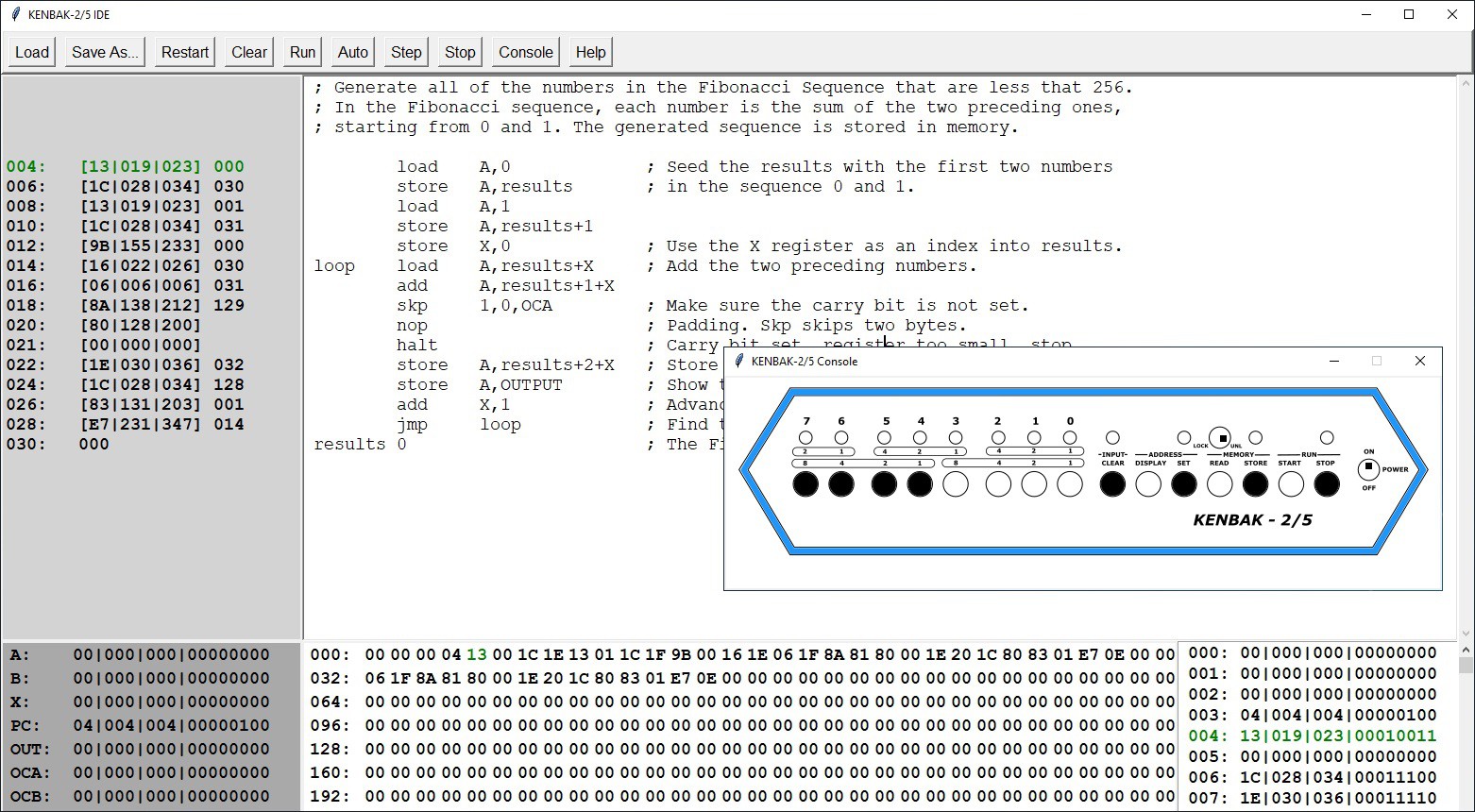
Here is a demonstration of the console simulator running my Fibonacci program written in KENBAK-1 assembler.
I have added a new script KENBAK_IDE_With_Console.py to my GitHub repository as I didn't want to alter the non Console version until I have done more testing. I'll combine the two in a bit. This script also requires the Front Panel Text Colored.png image.
Update 07/08/2021: I have integrate the Console into the main script now and created a release.
Added a Disassembler
I can't seem to stop wanting to improve my KENBAK-2/5 project, and anything that gets me "into the weeds" of the instruction set is especially appealing. To that end I have created a stand alone command line Disassembler. I have added the Python script to my GitHub repository and created a release.
Here is the online help:
usage: Disassemble a binary or delimited text file to KENBAK-1 source
       [-h] [-s] [-d] [-a] -f FILE

optional arguments:
  -h, --help            show this help message and exit
  -s, --save            save the disassembly to a .asm file
  -d, --dump            dump the disassembly to standard out
  -a, --address         add the instruction address to each line
  -f FILE, --file FILE  file to disassemble
Writing a disassembler is an interesting exercise, one that I had never undertaken before. Faced with an array of 256 raw bytes and trying to coax some meaningful structure out of it was pretty daunting.
The first thing I did was to determine which of the bytes represented the program code vs program data. Fortunately the first byte of code can be ascertained by looking at the fourth byte in memory which holds the PC (program counter/instruction pointer - defaults to 4). From that point, consecutive instructions can be readily resolved, that is until a "jump" instruction is encountered. By carefully following all of the jumps to other blocks of code you can create a map of all the code in the program.
All of the non-code bytes are then assumed to be data. But which of those bytes represent constants vs data bytes that will be manipulated by the program. Since all of the "registers" on a KENBAK-1 (A, B, X, PC, OUTPUT, AOC, BOC, XOC, and INPUT) are at fixed positions in memory that is a good place to start marking them as data bytes using a DB directive. The other bytes that will be written to can be determined by looking at all of the instructions that store to memory: STORE, SET, and JMK. Everything else is then treated as a constant.
Finally I did a pass to convert all of the memory references in the code to labels to make reading the emitted code a bit easier.
To test the disassembler I input the 256 byte "Day of the Week.bin" file created by the IDE assembler and compared the assembly output to the original code that I wrote. Furthermore I ran the disassembled code inside of the IDE to ensure that it indeed worked as expected.
Here is the original code:
; Program to calculate the day of the week for any date. To start this program you will
; have to input the date in four parts: Century, Year, Month, and Day. Each of the parts
; is entered as a two digit Binary Coded Decimal number (ie. the first digit will occupy ; bits 7-4 as a binary number, and the second digit bits 3-0) using the front panel data
; buttons. The steps to run this program are:
;
; 1) Set the PC register (at address 3) to 4.
; 2) Clear the input data then enter the date Century.
; 3) Press Start.
; 4) Clear the input data then enter the date Year.
; 5) Press Start.
; 6) Clear the input data then enter the date Month.
; 7) Press Start.
; 8) Clear the input data then enter the date Day.
; 9) Press Start.
;
; The day of the week will be returned via the data lamps using the following encoding:
; ;      7-Sunday 6-Monday 5-Tuesday 4-Wednesday 3-Thursday 2-Friday 1-Saturday
;
; All lamps turned on means the last item entered was invalid and you have to restart.
;
;
; Get the date we want the day for.
;    load    A,INPUT         ; Get the century.    jmk        bcd2bin    store   A,century    halt    load    A,INPUT         ; Get the year.    jmk     bcd2bin    store   A,year    halt    load    A,INPUT         ; Get the month.    jmk     bcd2bin    sub     A,1                ; Convert from 1 based to 0 based.    store   A,month    halt    load    A,INPUT         ; Get the day.    jmk     bcd2bin    store   A,day    load    A,0b10000000    ; Setup the rotation pattern.    store   A,rotate
; ; All the inputs should be in place. Start the conversion.
;    load    A,year          ; Get the year.    sft        A,R,2           ; Divide by 4.    store   A,B             ; Save to B the working result.    add     B,day           ; Add the day of the month.    load    X,month         ; Use X as index into the month keys.    add     B,monkeys+X     ; Add the month key.    jmk     leapyr          ; Returns a leap year offset in A if applicable.    jmk     working         ; Working...    sub     B,A             ; Subtract the leap year offset.    jmk     cencode         ; Returns a century code in A if applicable.    jmk     working         ; Working...    add     B,A             ; Add the century code.    add     B,Year          ; Add the year input to the working result.
chkrem          load    A,B             ; Find the remainder when B is divided by 7.    and     A,0b11111000    ; Is B > 7?    jmp     A,EQ,isseven    ; No then B is 7 or less.    sub     B,7             ; Yes then reduce B by 7.    jmk     working         ; Working...    jmp     chkrem          ; Check again for remainder.
isseven         load    A,B             ; Is B = 7?    sub     A,7             ; Subtract 7 from B value.    jmp     A,LT,gotday     ; No B is less than 7.    load    B,0             ; Set B to zero because evenly divisible.
gotday          load    X,B             ; B holds the resulting day number. Use as index.    load    A,sat+X         ; Convert to a day lamp.    store   A,OUTPUT    halt
error       load    A,0xff          ; Exit with error    store   A,OUTPUT        ; All lamps lit.    halt

;
; Store inputs.
;   century db
year    db
month   db  day     db

;
; Static table to hold month keys.
;
monkeys 1                       4        4        0        2        5        0        3        6        1        4        6

;
; Need to preserve A while performing some steps.
;
saveA   db
;
; Subroutine to blink the lamps to indicate working.
; rotate  db                  ; Pattern to rotate.
working db                  ; Save space for return adderess.    store   A,saveA         ; Remember the value in A.      load    A,rotate        ; Get the rotate pattern.    store   A,OUTPUT        ; Show the rotated pattern.    rot     A,R,1           ; Rotate the pattern.    store   A,rotate        ; Save the new rotation.    load    A,saveA         ; Restore the value of A.    jmp     (working)       ; Return to caller.
    org 133                 ; Skip over registers.

;
; Subroutine takes a BCD nuber in A as input and returns the equivalent binary number ; also in A.
;   bcd2bin db                  ; Save space for return address.        store   A,X             ; Save A.    sft     A,R,4           ; Get the 10's digit.    jmk     chkdig          ; Make sure digit is 0 - 9.    store   A,B             ; B will hold the 10's digit x 10 result    add     B,B             ; B now X 2    sft     A,L,3           ; A is now 10's digit X 8    add     B,A             ; B now 10's digit X 10    store   X,A             ; Retrieve original value of A    and     A,0b00001111    ; Get the 1's digit value in binary.    jmk     chkdig          ; Make sure digit is 0 - 9.    add     A,B             ; Add the 10's digit value in binary.    jmp     (bcd2bin)       ; A now has the converted BCD value.

;
; Subroutine determines if the date is a leap year in January or February and returns
; an offset of 1 if it is, and 0 otherwise.
;
leapyr  db                  ; Save space for return address.        load    A,month         ; Check to see if month is January or February.    and     A,0b11111110    ; Are any bits other than bit 0 set?    jmp     A,NE,notlpyr    ; Yes then not January or February. Return 0.    load    A,year          ; Is this an even century?    jmp     A,NE,chkyear    ; No then have to check the year.    load    A,century       ; Yes so see if century evenly divisible by 4.    and     A,0b00000011    ; Are bits 1 or 0 set?    jmp     A,EQ,islpyr     ; Yes evenly divisible by 4 and is a leap year.    jmp     notlpyr         ; No this is not a leap year.
chkyear         load    A,year          ; See if rear evenly divisible by 4.        and     A,0b00000011    ; Are bits 1 or 0 set?    jmp     A,NE,notlpyr    ; Yes so not evenly divisible by 4 and not a leap year.
islpyr      load    A,1             ; Offset 1.    jmp (leapyr)            ; Return offset.    notlpyr     load    A,0             ; Offset 0.    jmp (leapyr)            ; Return offset.
;
; Subroutine determines if a century code needs to be applied to the calculation.
;
cencode db                  ; Save space for return address.    load    A,century       ; Century must be between 17 - 20.
chkmin      sub     A,17            ; Is century less than 17?    jmp     A,GE,chkmax     ; Yes so century >= 17. Check max boundry.    load    A,century       ; Increase century by 4.    add     A,4    store   A,century    jmp     chkmin
chkmax      load    A,century       ; Century must be between 17 - 20.    sub     A,20            ; Is century greater than 20?    jmp     A,LT,retcode    ; No so calculate century code.    jmp     A,EQ,retcode    load    A,century       ; Decrease century by 4.    sub     A,4    store   A,century    jmp     chkmax+2
retcode     load    X,century       ; Calculate the century code    sub     X,17            ; Create an index into the century codes.               load    A,ctcodes+X     ; Get the appropriate century code.    jmp     (cencode)       ; Return century code.          ;
; Subroutine that checks if the digit passed in A is in range 0 - 9.
;
chkdig  db                  ; Save space for return adderess.    store   A,saveA         ; Remember value in A.    load    A,9             sub     A,saveA         ; Subtract value passed from 9.    and     A,0b10000000    ; Is negative bit set?    jmp     A,NE,error      ; Yes so value in A not in range 0 - 9.    load    A,saveA         ; No so A value in range.     jmp    (chkdig)         ; Return to caller.

;
; Static table to hold the output pattern for the day of the week.
;
sat     0b00000010
sun     0b10000000
mon     0b01000000
tues    0b00100000
wed     0b00010000
thur    0b00001000
fri     0b00000100

;
; Static table to hold century codes.
;
ctcodes 4
        2
        0
        6
And here is the disassembled code:
                     org      0
A          0
B          0
X          0
PC         4
           load     A,INPUT
           jmk      LAB133
           store    A,LAB094
           halt
           load     A,INPUT
           jmk      LAB133
           store    A,LAB095
           halt
           load     A,INPUT
           jmk      LAB133
           sub      A,1
           store    A,LAB096
           halt
           load     A,INPUT
           jmk      LAB133
           store    A,LAB097
           load     A,128
           store    A,LAB111
           load     A,LAB095
           sft      A,R,2
           store    A,B
           add      B,LAB097
           load     X,LAB096
           add      B,LAB098+X
           jmk      LAB156
           jmk      LAB112
           sub      B,A
           jmk      LAB189
           jmk      LAB112
           add      B,A
           add      B,LAB095
LAB062     load     A,B
           and      A,248
           jmp      A,EQ,LAB074
           sub      B,7
           jmk      LAB112
           jmp      LAB062
LAB074     load     A,B
           sub      A,7
           jmp      A,LT,LAB082
           load     B,0
LAB082     load     X,B
           load     A,LAB243+X
           store    A,OUTPUT
           halt
LAB089     load     A,255
           store    A,OUTPUT
           halt
LAB094     0
LAB095     0
LAB096     0
LAB097     0
LAB098     1
           4
           4
           0
           2
           5
           0
           3
           6
           1
           4
           6
LAB110     0
LAB111     0
LAB112     0
           store    A,LAB110
           load     A,LAB111
           store    A,OUTPUT
           rot      A,R,1
           store    A,LAB111
           load     A,LAB110