 Joe Wingbermuehle
The high gate capacitance of the 2N7002 transistors that the Q2 uses prevents it from running much faster than 80 kHz without becoming unstable. This is because, with resistor pull-ups, the charge stored in the gates is pulled high through the resistor, causing slow rise times when a lot of gates are connected together.
Consider the A register in the Q2, which is 12 bits. To clock the A register, 2 transistor gates per bit need to be pulled high. This is a fanout of 24, so a capacitance of 50pF * 24 = 1200pF. The threshold voltage of a 2N7002 is 2.5V worst-case. If we pull this high through a 10k resistor, we get the following expression for the rise time:
Solving for t we get 8.3us for a single gate (if there were only one level of logic, the frequency would be limited to 120 kHz, but there are more levels involved). Substituting a 1k resistor solves the problem, but introduces another: instead of using 0.5mA, we use 5mA. This power draw quickly adds up.
The control lines of the Q2 are carefully designed to use 10k resistors where possible, and fall back to 1k in just enough places to allow stable 80 kHz operation. Unfortunately, going faster becomes increasingly difficult and wastes more power. This raises the question of whether another transistor would be more suitable.
We want the following characteristics:
- Low gate capacitance (lower than 50pF)
- Low threshold voltage. Not only does a high threshold cause problems with the supply voltage, it also makes the computer slower since the gate output needs to reach a higher voltage, which takes longer.
- Low price. When using 1000s of transistors, we can't ignore the price.
- ESD protection. Not strictly necessary, but certainly nice to have. With lower gate capacitance, this is probably more important.
One transistor that seems to be a good contender is the 2SK3018 (Shikues brand available through LCSC). It has a gate capacitance of 13pF and threshold of 1.5V. This means that in our example, the delay would be 1.1us with a 10k resistor and 0.11us with a 1k resistor. This should allow running the Q2 at nearly 8x the clock speed and/or save some power.
To investigate this further, I put together a simple test circuit. to see how the transistors compare:
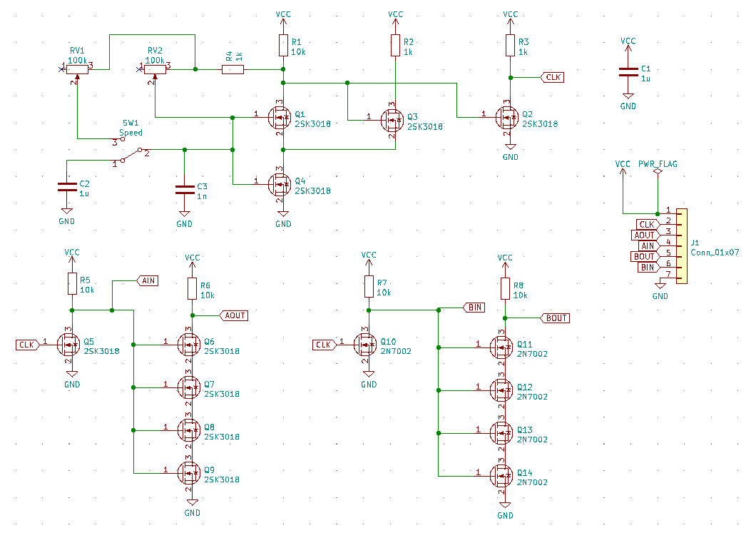
The circuit is a simple relaxation oscillator (identical to the oscillator used in the Q2, but implemented using 2SK3018s instead of 2N7002s). The output is run through two circuits with a fanout of 4 using both types of transistors so I can compare the rise times. This circuit will also allow me to try out an SMD switch so I don't have to worry about soldering switches in future revisions.
Discussions
Become a Hackaday.io Member
Create an account to leave a comment. Already have an account? Log In.