I should have my test board for the 2SK3018 transistors back next week, but in the meantime I've been thinking about other changes.
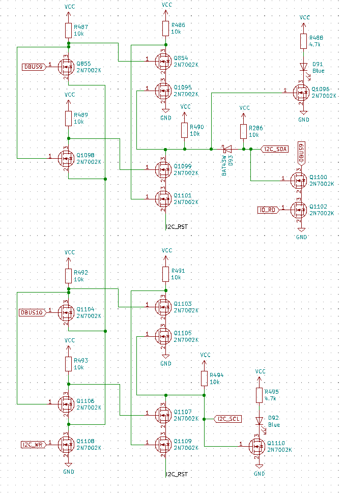
In the interest of adding more I/O capabilities, I think I've settled on adding an I2C interface to the Q2. I2C is pretty easy to support, requiring 2 open-drain outputs (SDA for data and SCL for a clock), and an input (only SDA assuming there isn't a need for clock stretching).
To implement the output for I2C is the most complicated, requiring a latch for SDA and SCL. Input is easy, requiring only a single NAND gate. Here's the current proposal:

The idea is that bit 11 of address 0xFFF will select between the LCD (0) and I2C (1), allowing easy access to the LCD just as before. When bit 11 is set, bit 10 sets SCL and bit 9 sets SDA. The software for I2C is fairly simple. For start/stop, I think something like this should work:
.def I2C_EN   0x800
.def I2C_SCL  0x400
.def I2C_SDA  0x200

; Note I2C signals are inverted.
i2c_zero:
  .dw   I2C_EN | I2C_SDA | I2C_SCL
i2c_zero_clk:
  .dw   I2C_EN | I2C_SDA
i2c_one:
  .dw   I2C_EN | I2C_SCL
i2c_one_clk:
  .dw   I2C_EN
i2c_input_mask:
  .dw   ~I2C_SDA

; Send I2C start
; Take SDA low while SCL stays high.
i2c_start:
  sta   =x1
  lda   i2c_one_clk   ; SDA=1, CLK=1
  sta   @=neg1
  lda   i2c_zero_clk  ; SDA=0, CLK=1
  sta   @=neg1
  jmp   @=x1

; Send I2C stop
; Take SDA high while SCL stays high.
i2c_stop:
  sta   =x1
  lda   i2c_zero_clk    ; SDA=0, CLK=1
  sta   @=neg1
  lda   i2c_one_clk     ; SDA=1, CLK=1
  sta   @=neg1
  jmp   @=x1
For writing, we just loop over each bit. Being a 12-bit architecture, we have to shift off 4 bits first. So, something like:
; Write byte in x0.
; Destroys x0-x2
i2c_write:
  sta   =x1

  ; Shift out high 4 bits
  lda   =x0
  add   =x0
  sta   =x0   ; x2
  add   =x0
  sta   =x0   ; x4
  add   =x0
  sta   =x0   ; x8
  add   =x0
  sta   =x0   ; x16

  lea   =8
i2c_write_loop:
  add   =neg1
  sta   =x2

  lda   =x0
  add   =x0
  sta   =x0
  jfc   i2c_write_zero

  ; Write 1
  lda   i2c_one
  sta   @=neg1
  lda   i2c_one_clk
  sta   @=neg1
  lda   i2c_one

  jmp   i2c_write_cont
i2c_write_zero:

  ; Write 0
  lda   i2c_zero
  sta   @=neg1
  lda   i2c_zero_clk
  sta   @=neg1
  lda   i2c_zero

i2c_write_cont:
  sta   @=neg1
  lda   =x2
  jfc   i2c_write_loop

  ; Acknowledge
  lda   i2c_one
  sta   @=neg1
  lda   i2c_one_clk
  sta   @=neg1
  lda   i2c_one
  sta   @=neg1

  jmp   @=x1
Reading is similar. From simulation, this would make reading 256 bytes from an EEPROM take somewhere in the neighborhood of 26 seconds at a 80kHz clock. It would be nice to get this faster, but that's plenty fast to use some I2C sensors or a real-time clock, etc.
 Joe Wingbermuehle
Discussions
Become a Hackaday.io Member
Create an account to leave a comment. Already have an account? Log In.