 filip.szkandera
Almost every electronics device uses some kind of a microcontroller nowadays. The thing is, that these chips can be very complicated, and even though you can buy them very inexpensively (like Arduino for example), I've still wanted to take a deeper look into them and understand their inner workings. I soon realised, that I have only a few options to do that:
- Study an existing microcontroller from a datasheet
- Make some kind of a emulator (C / Python)
- Build my own CPU from scratch
You can already guess which path I took.
1. Designing my own CPU:
I discovered Ben Eater's homemade CPU on Youtube and I was so mesmerised and almost immediately got to work. I've improved his design and built myself an 8 bit CPU too. This article is not about that one though. If you want to, you can check out my photos in this Twitter post. I may write another article about that someday.
At this point, I had a pretty good understanding of a really basic CPU, but for some reason, this wasn't enough for me. Shortly after that, I've stumbled across Robert Baruch's Youtube channel and he started working on a 32 bit RISC-V CPU, which also used just a basic logic components. I have done some research about RISC-V and found out, that it is completely open-source and well documented.
Me being me, I started making my own RISC-V CPU implementation in a program called Logisim-Evolution. Again I set my goal not use ANY microcontrollers or FPGAs in my build - just basic discrete logic components. So, what exactly am I going to build? I needed to NOT set too a high goal for myself, so I would be able to finish this project in *relatively* short time (Is 2yrs short enough? :-) ). The most basic RISC-V CPU, that is supported by compilers, must include the extension "I" (Integer) and it must be at least 32 bit. So now I had all the information I'm going to need, so it was time to start building. Oh, and did I mentioned that I was going to put a VGA output card on as well? (VGA card inspired by Ben Eater; https://eater.net/vga)
After 6 months of fiddling with Logisim, I had a working "simulation". The next step would be to create schematics for all of the modules, design all PCBs and order them from JLCPCB. But, as this would be my first time ordering PCBs, I didn't want to screw up everything - so I separated the design into modules, and chose few at a time, so as to not overwhelm myself. JLCPCB had a discount for a 2 layer PCB with dimensions < 100mm x 100mm, and I've tried my best to fit into these dimensions to keep the lower cost (and I've managed to fit it in!).
So, now I have a working simulation and my plan is to take few modules at a time, turn them into proper schematics, make a boards and order them. This isn't the best way to do things, but otherwise it would be too much for me. (foreshadowing)
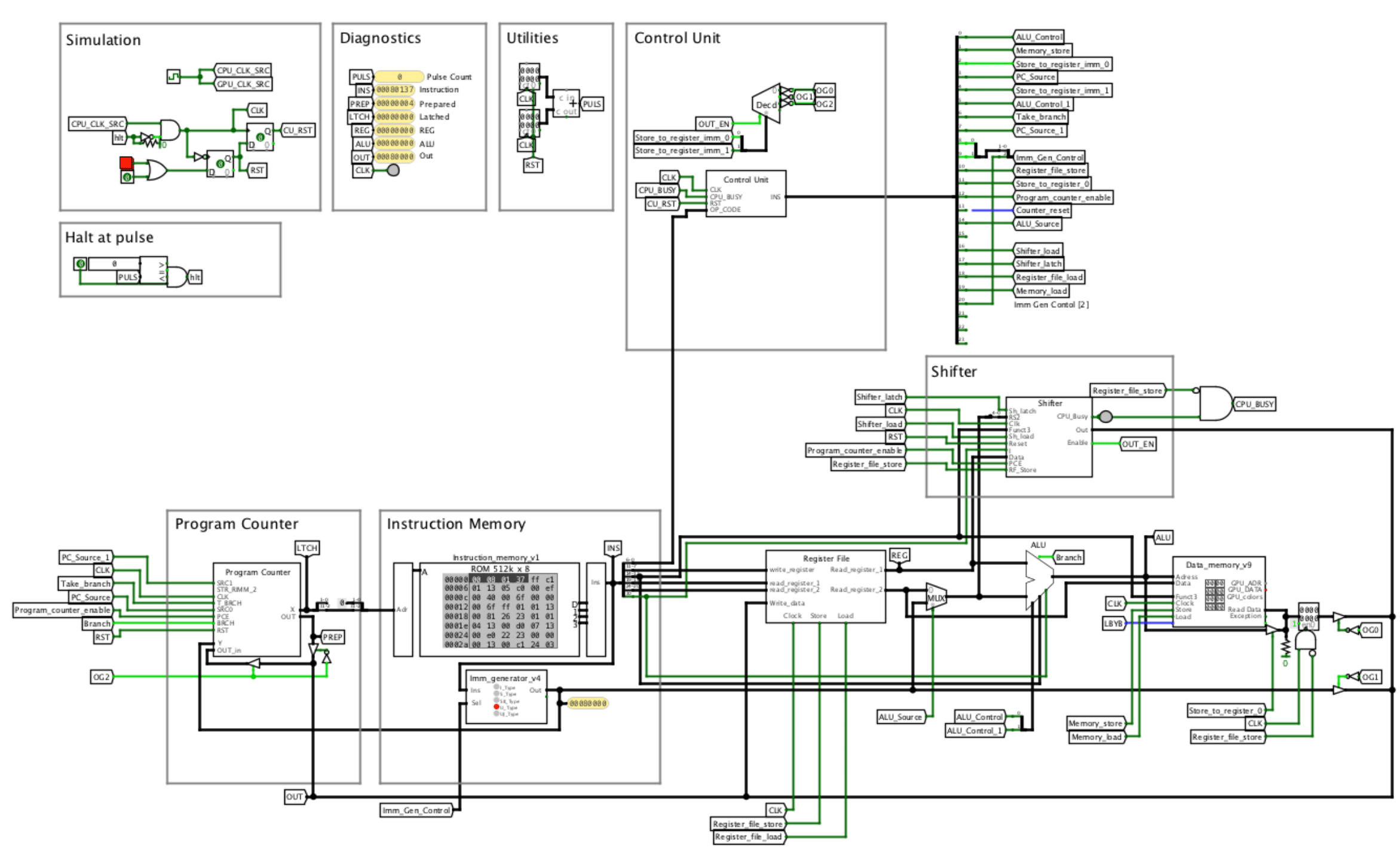
Photo of my Logisim-Evolution simulation
After 2 batches, all that remained were a few modules and one of them is called immediate generator. When I was looking into ways I could turn it from my simulation into proper schematic, I realised that I made a fatal mistake and that I had absolutely no idea how the simulation could have worked. Luckily, the repairs weren't that hard and I was able to easily retrofit one of already made PCBs to completely repair it.
2. Prototype
I knew that this project would be large and I would almost certainly make some mistakes (we are talking about 230+ ICs), so I've decided to start with a prototype, where I have access to all signals and can easily debug the whole thing - I'm not (yet) an electrical engineer and I'm only 19, so this seemed to be a good idea (and it really was).
After I received my PCBs, I've tested each and every one of them by connecting an Arduino to its inputs and simultaneously monitoring its outputs and comparing it to a prediction. Once I've set it up, it was all automatic and to test as much possibilities each test ran at least few hours.
When I was ready to put it all together, I've spaced out my modules onto a piece of wood and secured them with a 3D printed spacers. I then uploaded a test program and begun testing. This is where the fun begins.
Photo of my prototype:
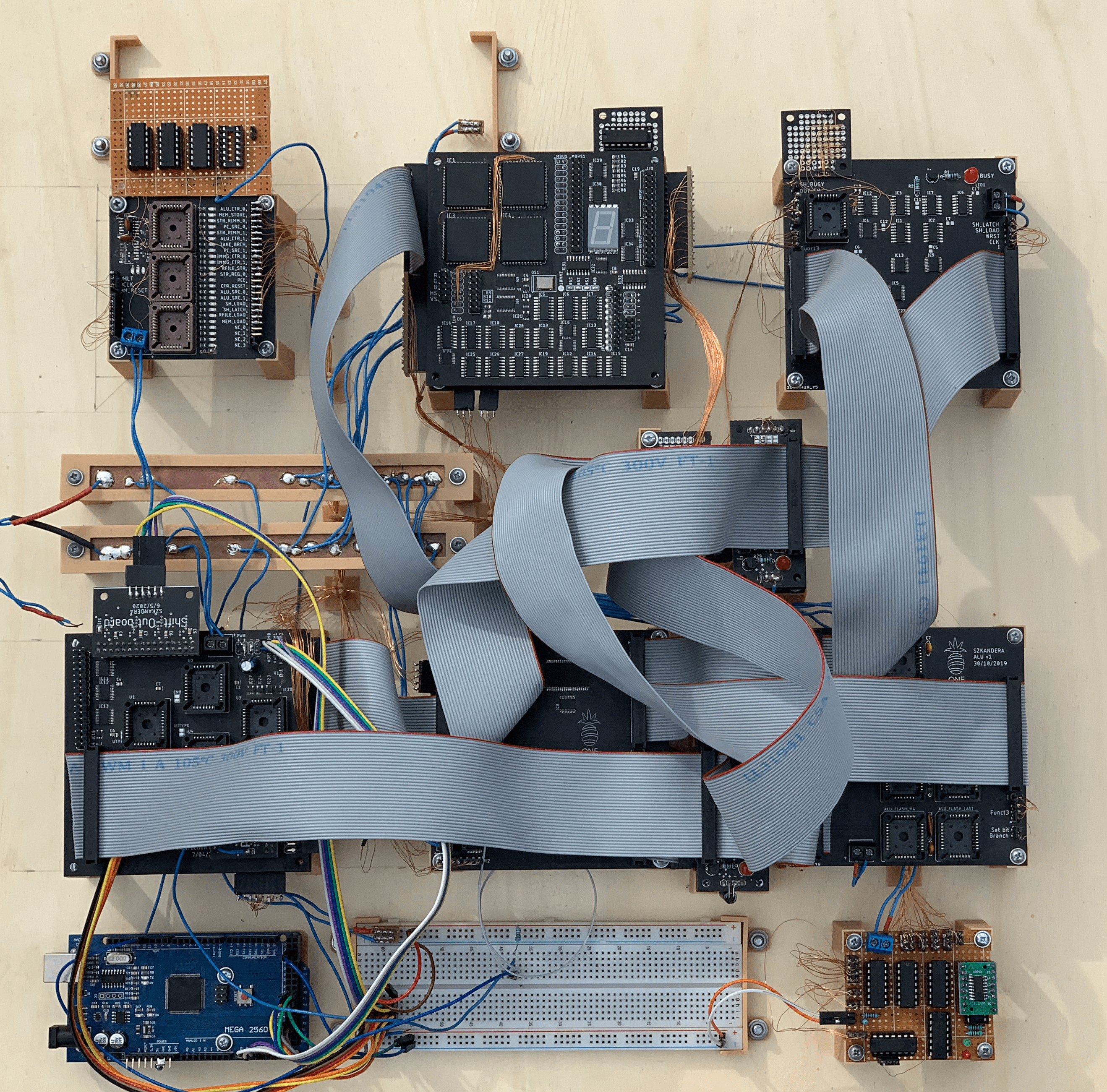
The Arduino is used only for debugging purposes (it is not present on the final version)
It is no surprise, that It din't work on a first try, even though I've tested every single PCB individually. It took a loooot of work, until I found all the little things that were wrong. For example, there was a timing problem, which was very hard to find.
3. Input/Output
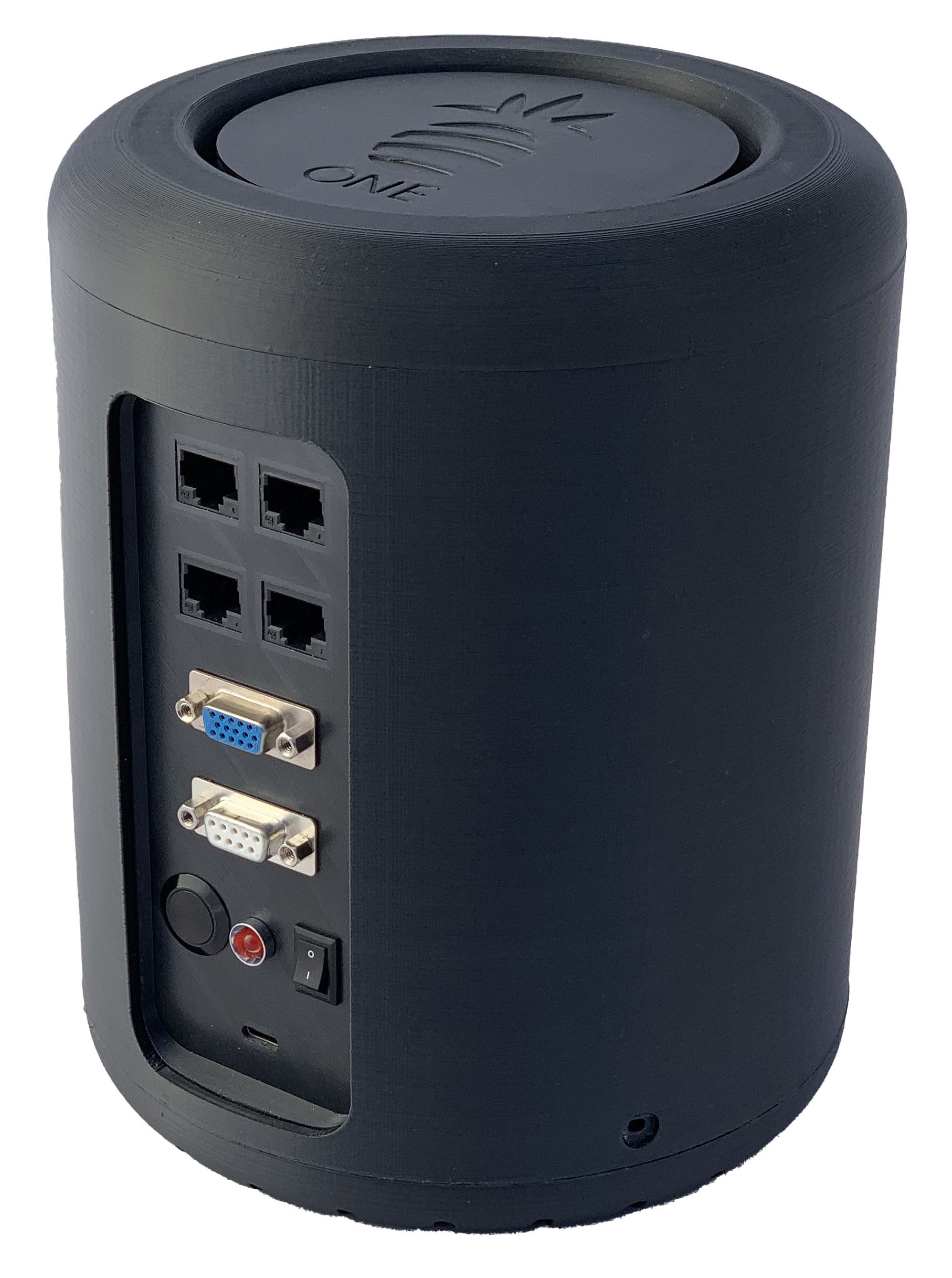
My CPU has a two 8-bit input and two 8-bit output ports, that you can access on the front panel via RJ50 connector. You can also notice a 7-segment display on the top module, which is connected to a register that can be accessed by a program. For connecting a VGA monitor, I've built a VGA card, inspired by Ben Eater (https://eater.net/vga). VGA output resolution is 200x150 pixels, black and white (I've tried to add colors, but I would need to use larger V-RAMs which are significantly expensive).
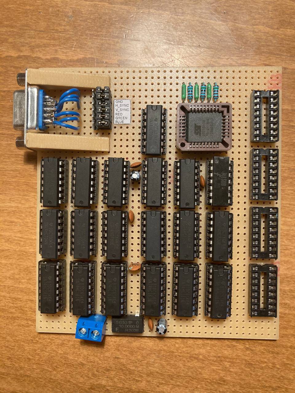
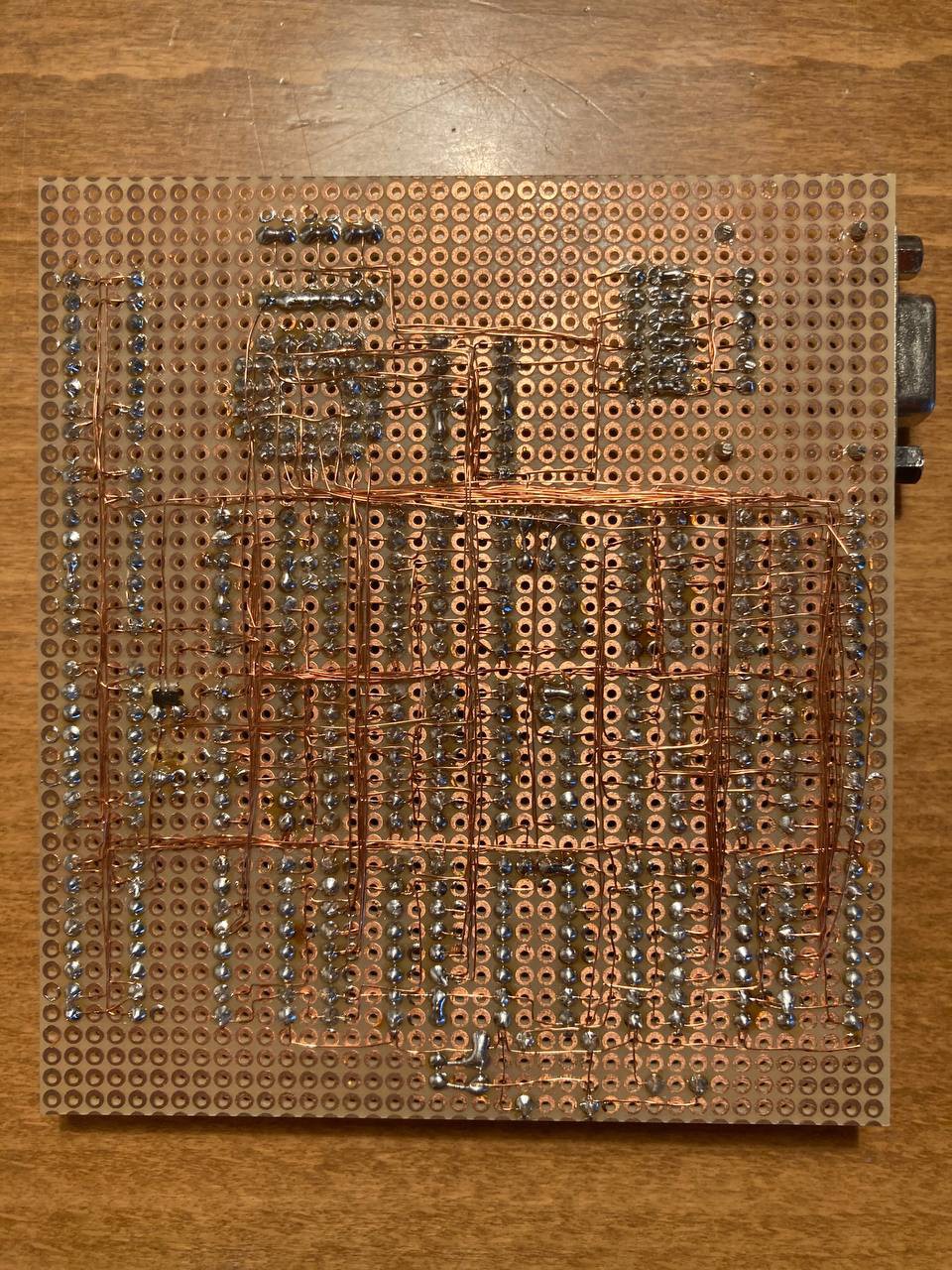
Before I ordered that VGA card, I felt the need to test it out before, just to be sure - so I did!
This board will display a static image stored in the EEPROM (39SF010A). I will use a dual-port SRAM on the final version.
 |  |
I've also created some I/O modules for demonstration (They all have RJ50 connector at the end).
| LED Module | Button Module | PS/2 decoder |
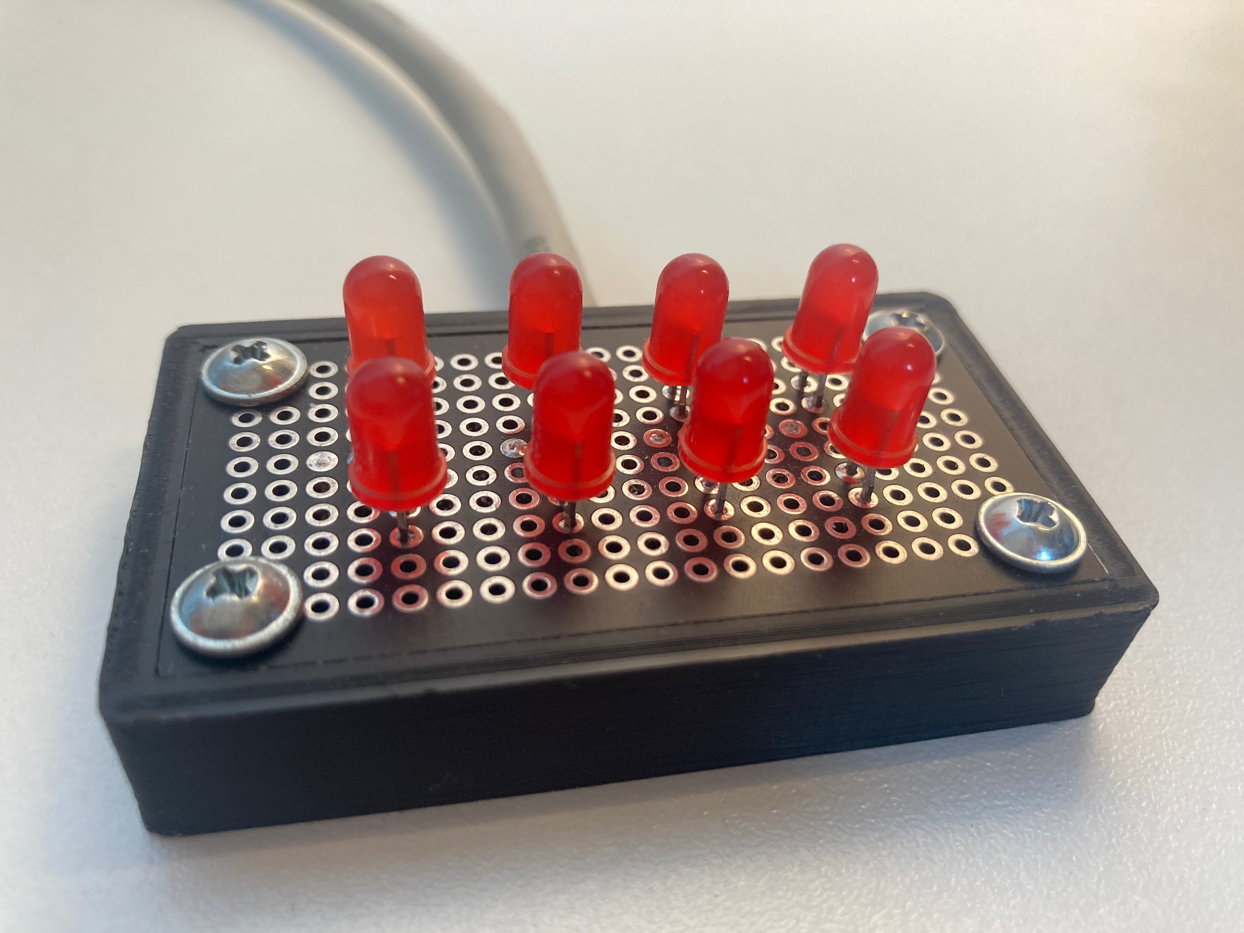 | 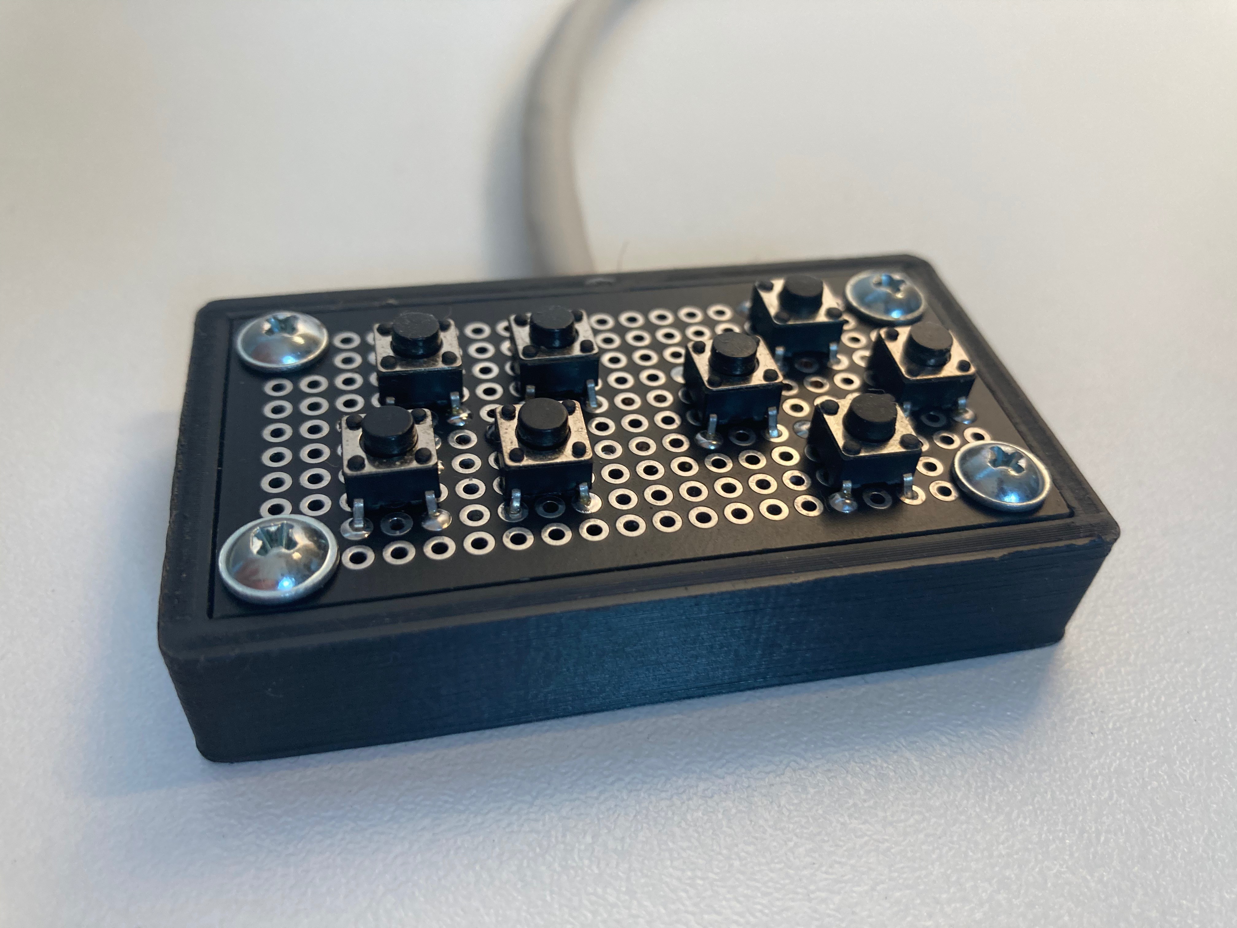 | 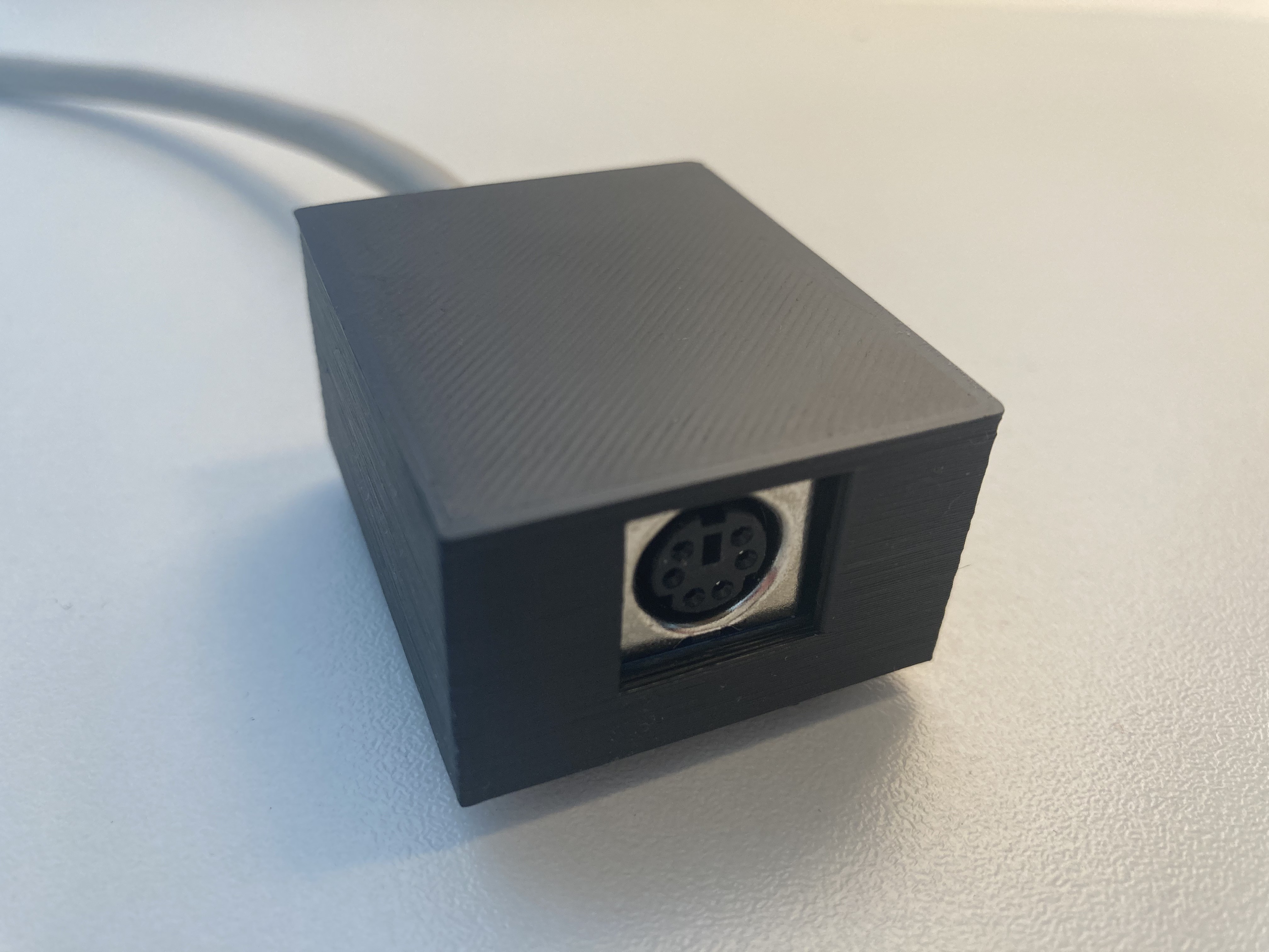 |
PS/2 decoder has a store-bought decoder - I was short on time to develop my own
4. Final version
Getting the prototype to work wasn't easy (like - at all), but after about 5 months of work I managed to to that.
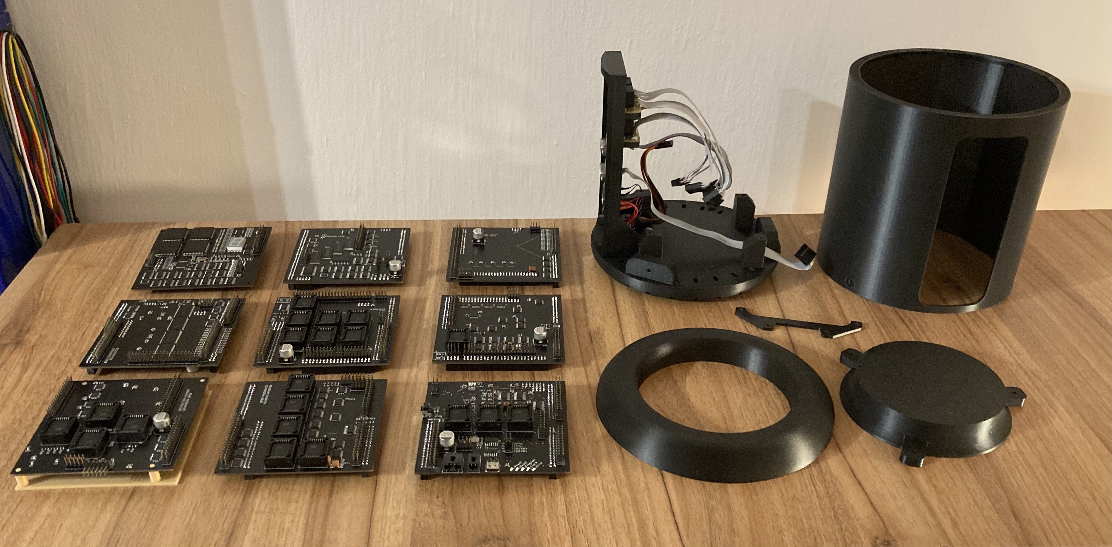
I then redesigned all my PCBs to repair my mistakes and to make them stackable in a tower-like structure, so every module can be connected only via pinheaders. This wasn't that hard compared to what I've already done. This redesign took about three months and then I've ordered my final PCBs. I've design an enclosure and printed it on a Prusa i3 3D printer.
Final version: (without the top part)
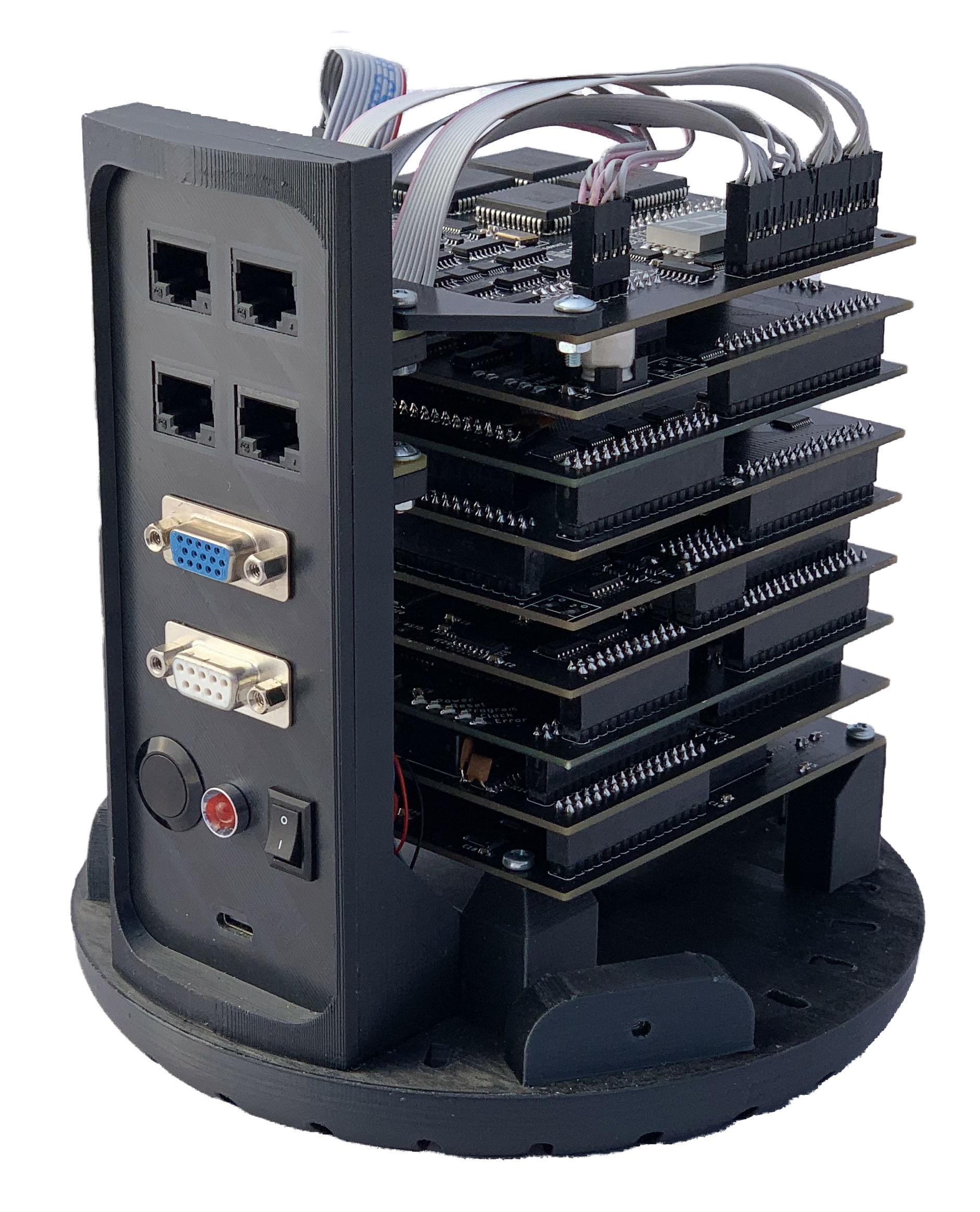
Final version: (with the top part)
Disassembled final version:
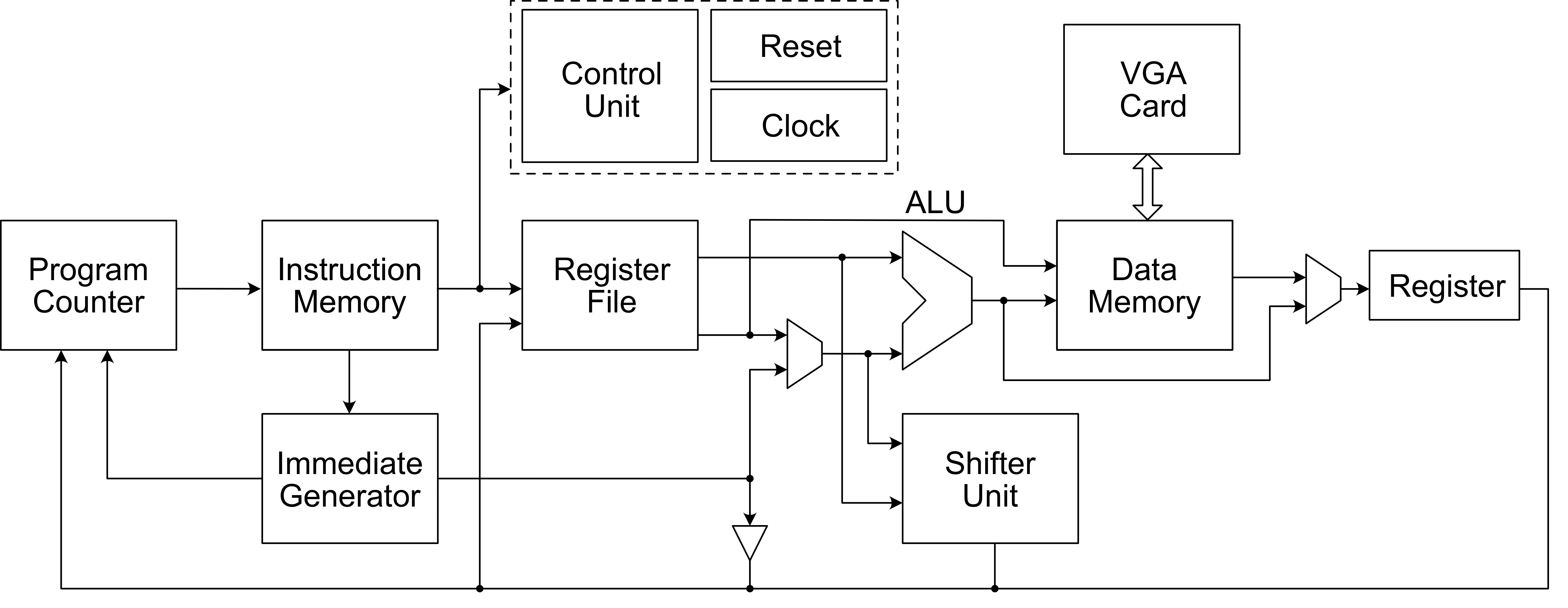
Block diagram:
5. Programming
Finally, after hundreds of hours of designing, soldering and debugging, I could finally see the light at the end of a tunel. Jan Vykydal helped me with setting up a compiler to work properly, so I could write my programs in C (I programmed some functions in assembly as well).
// Sum two numbers

int main (void){
    while(1){
        // Load first operand from port A
        char operand_A = SR->INPUT_A;

        // Load second operand from port B
        char operand_B = SR->INPUT_B;

        // Outputs the sum of port A and B to port C
        SR->OUTPUT_C = operand_A + operand_B;
    }
}
I created a library with some useful functions, like:
// Turn on a specific pixel on screen
void writePixel(int x, int y);
// Turn off a specific pixel on screen
void clearPixel(int x, int y);
// Write ASCII character on screen
void writeChar(int x, int y, char arr[]);
// Clear screen
void VGA_clear();
// Turn on/off VGA output
void VGA_power(const uint8_t state);
// Square root
int32_t lib_math_sqrt(int32_t x);
// Power
int32_t lib_math_pow(int32_t base_i, int32_t exponent_i);
With the library I was able to create a simple shell program, which you could interact with via PS/2 keyboard connected to one of the input ports (I use PS/2 keyboard with a module to decode input signals into 8 bits).
Pineshell:
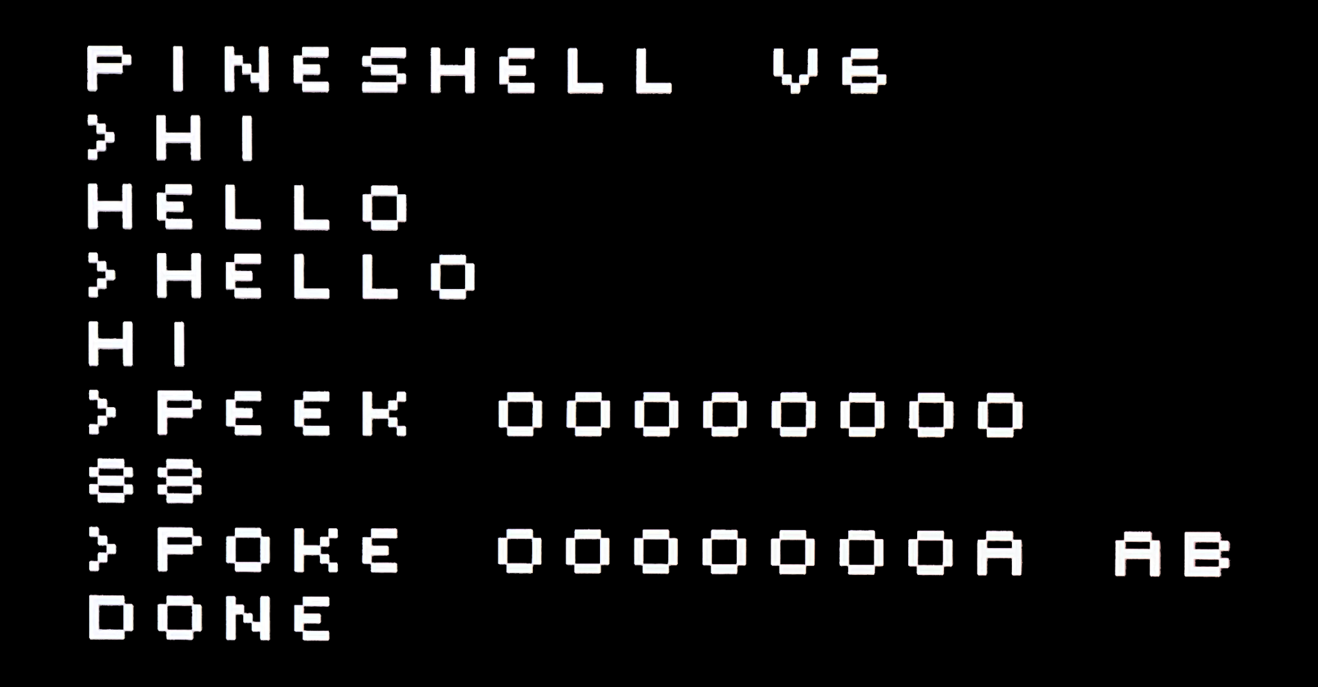
Currently supported commands:
- HELLO
- HI
- PEEK <ADDRESS>
- POKE <ADDRESS> <DATA>
- SYSTEM INFORMATION
- CLEAR
- RUN SNAKE
Yes, RUN SNAKE launches a VERY simple snake game ;)
6. Details
This CPU won't break any speed records, but what can you expect with just a discrete logic chips. It runs relatively stable on 500 kHz, anything above will introduce computing errors (wasn't able to figure out why yet - maybe parasitic capacitance? Even on 500k you can sometimes see a glitch :( - still need some improvements). It has a 512kB of program memory and 512kB of RAM - which is OK for such device.
7. Demo 1
I used a VGA->HDMI adapter in this video, hence the cropped image on the TV
7. Conclusion
I am VERY happy to see it finally running, it wasn't easy, but I made it. There are many things that could be improved, but we'll see.