 Chromico
Let’s make Aluminum PCBs using KiCad

We usually see printed circuit boards ( PCBs ) use FR4 ( fiberglass ) as the substrate. There are all kinds of materials that can be used for the substrate but I’ll be taking a look at Aluminum PCBs which are also commonly used, design one using KiCad, and get it manufactured. Let’s get started!
How do Aluminum PCBs work?
First, we need to understand how Aluminum PCBs work. The stack-up diagram below shows how a 1 Layer Aluminum PCB works. There are also multilayer Aluminum PCBs but we’ll be taking a look at a 1 Layer one for now.
The solder mask layer protects the copper layer ( our circuit layer ) from oxidization and solder bridges when soldering. To prevent everything from shorting because of the aluminum layer, there is a thin fiberglass ( FR4 ) layer to prevent that from happening.

Why use it in your project?
- Better heat dissipation
- Much more durable
- Environmentally friendly
- Lightweight
But with some cons
- Harder to solder because of the larger thermal mass
- Slightly rougher edges
Designing one using KiCad
I used KiCad as it’s free and open source. Designing an Aluminum PCB in KiCad is quite easy but however, you’ll need to adjust a few things like the DRC ( Design Rule Check ) which checks things like the minimum or maximum track spacing, hole size, traces, and so on. You can do it manually with the measuring tool in KiCad but that’s very inconvenient and inefficient.
What came to mind was to design an LED panel using aluminum PCBs because that was guaranteed to get hot pretty fast at full brightness. I decided to go with some 1210 LEDs that I got from eBay a while back and never ended up using it until now.
Schematic
The LEDs are connected both in parallel and in series. If I connected all the LEDs in series I would need a higher voltage but less current. If I connected them in parallel I would need a lower voltage but a higher current. It was a pain in the neck figuring out which method to go with but in the end, I went with both after doing some research on the net. I did a bit of math and calculated the voltage to be +15V. For the current, it would be around 100-200ma.

Printed Circuit Board ( PCB ) Layout

Getting the PCBs made
Thankfully PCBWay offers a decently priced Aluminium PCB prototype service that you can check out here. They also make regular FR4 PCBs, offer PCB assembly and all kinds of cool services. Huge thanks to them for providing the PCBs + stencil used in this project 
When I received it, everything seemed to be packed well. As always the quality was good 


Assembling the PCBs
I assembled two kinds of boards. The first one was the aluminum one and the other was the regular FR4 one. I did this so that I can compare the boards during testing.
Applying the solder paste
Using some of the extra PCBs, I made a jig to hold the PCB in place. I then used some lead-free solder paste and applied it on the stencil with a plastic card. With the magic of video editing, I tried making the process look cool in the video below.
Soldering
After placing the components I used my trusty cheap generic 858D hot air soldering station to solder the components in place. The Aluminum PCB requires a higher reflow temperature as it has a larger thermal mass to heat up. The only issue there is that you’ll need to make sure that some of the components don’t melt or deform. So just watch out for that. You can see an example of what I mean in the picture below.

Testing

I made use of this super cheap LED power supply I got a while back. I tried using my regulated power supply but it blew up the first board ( 25 LEDs went to waste  ). For the thermal testing, I used one of these IR ( Infra-Red ) thermometers to get a rough estimate of the temperature values ( in degrees celsius ). Not the best accurate method but it was enough to show the thermal performance between the 2 boards.
The image on the left is...
Read more »
 Michael Delaney
 Erik Bosman
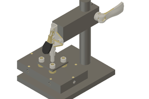
 Jayken
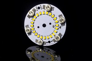
 SAYANTAN PAL