-
1Step 1
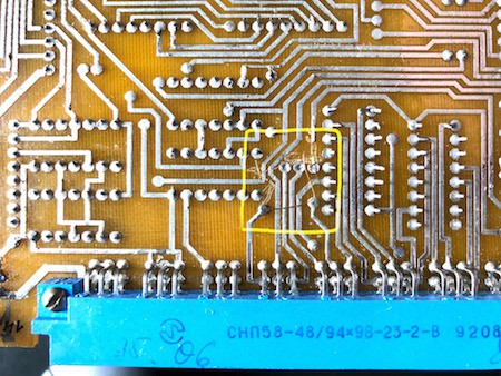
The MC6205 bottom PCB must be changed to support the additional 'faked' data bit.
Please check your MC6205 schematics against my published one, because they could be slightly different, same for the PCB.![]()
-
2Step 2
Driver PCB: (Attention)
If you plan to use the MP2307 step-down converter module to provide the 5V for the logic components and Arduino, you have to trim it with the onboard potentiometer. So before you solder it on the PCB, please set it up to 5V ! -
3Step 3
Run your code to display the standard character set (original EPROM) but with advanced character range.
Be surprised... -
4Step 4
Change the original EPROM:
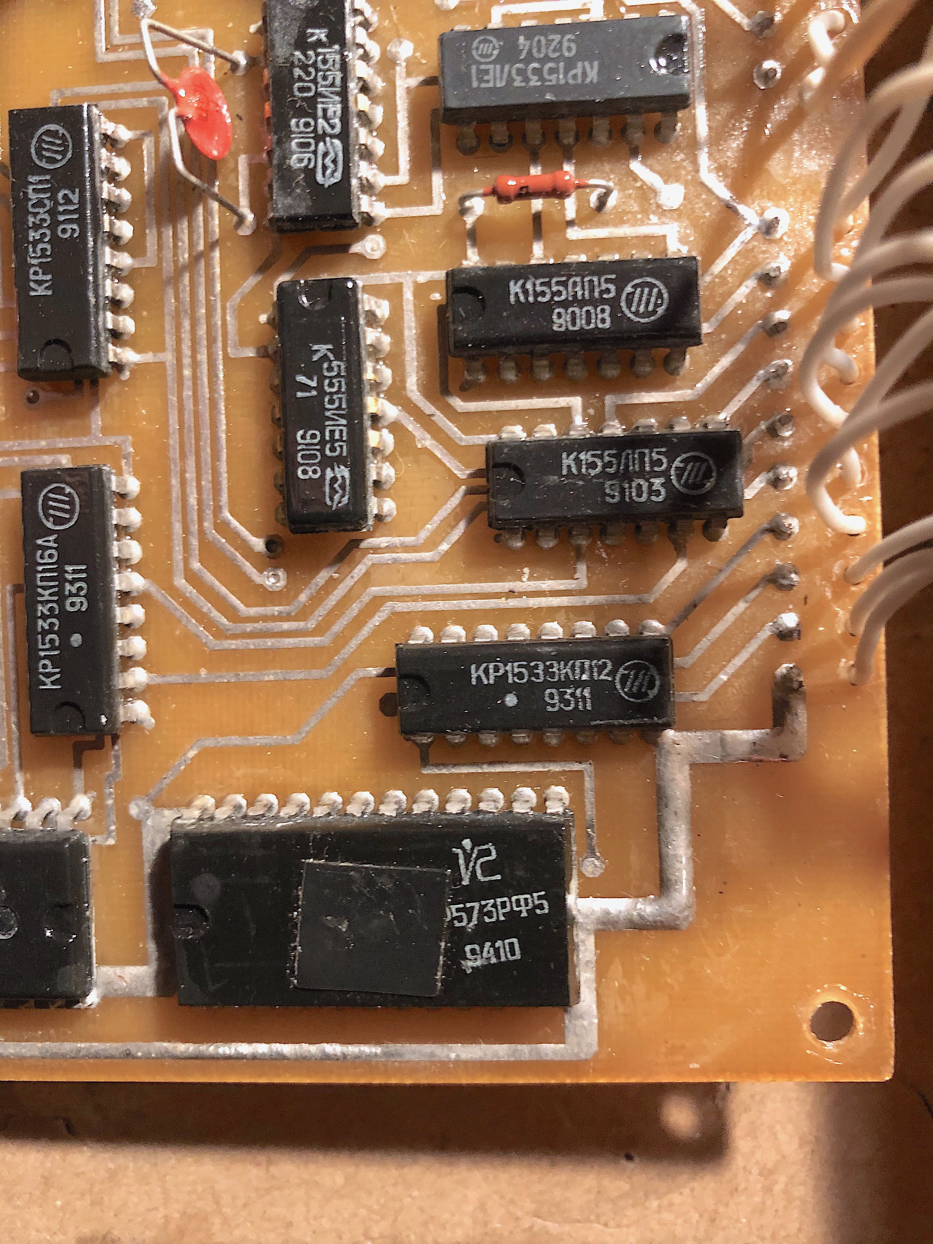
To get the ISO charset, you have to swap the original EPROM КР573РФ5 (KP573RF5 == 2716) with the custom programmed one.
Original:
![]()
Custom one:
In the picture a X2816CP EEPROM is used. Much more simpler to program, I can recommend this EEPROM.
![]()
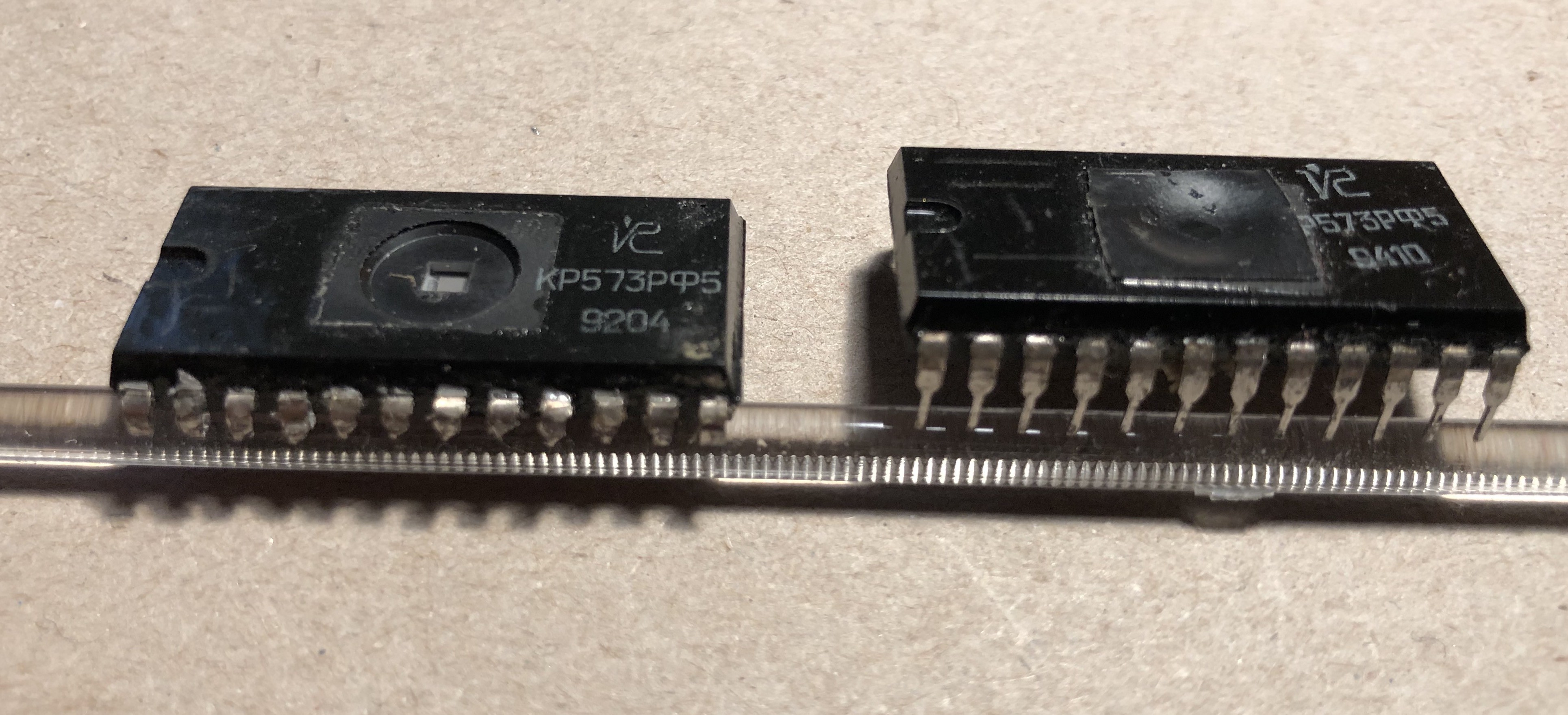
The old EPROM:
one desoldered with pins preserved, one without.
![]()
-
5Step 5
Software:
In the files section, you will find a zip with test-software for the MC6205.
You can compile it with the Arduino IDE or Visual-Studio Code + PlatformIO.
MC6205/MS6205 | ESP32 Weatherstation, NTP Clock
Weatherstation based on MC6205 (MS6205) russian gas discharge (Plasma) display using ESP32
 jörg postert


Discussions
Become a Hackaday.io Member
Create an account to leave a comment. Already have an account? Log In.