I wanted to power a solenoid valve for a short pulse. I used a 555 board & an SSR board. It worked OK but not very convenient. Once I'd hacked the 555 board with reasonable R & C values, the timing pot was pretty coarse & any bump would change it. I needed to be able to set different pulse lengths for different uses and select between them instantly & reliably. But most of all, I need the pulse to be on for a maximum - even if I've left my thumb on the button for longer than the pulse should be. The 555 is fantastic for a couple of pulse scenarios but there are many useful pulse patterns that can't be done even with a 556.
The ESP-01 (S or not) has at least 2 usable GPIO pins for the trigger & output and they are cheap and common like the 555. It was easy to program a GUI full of simple & elaborate pulse pattern choices to use from any browser by WiFi. There are a few different ESP-01 relay modules available cheaply but they seem to all have problems of some sort. I've seen 3 slightly different designs which all glitch the relay during power-on or reset. In some uses this could literally be fatal. Another design uses a second micro-controller to avoid the glitch but is awkward to use and many fakes are sold unprogrammed. To use these boards I also bought a breadboard break-out and a programmer (to which I had to add PRG & RST buttons). But worst was that I had to move the ESP-01 from the relay module to the programmer every time I wanted to make a change.
So I made a list of wants & needs and designed a better ESP-01 relay board with all the trimmings, optional wherever possible to enable the same PCB to be used in many different configurations. I tested the proof-of-concept by modifying one of the other boards: cutting tracks & soldering new components onto the exposed pins of others. As with the modification of the original 555 board, this was a time consuming & fiddly pain so I resolved to make my version as hackable / DIY-friendly as possible. Hence the combination of SMT & THT with header pins, mounting holes and a less cramped size, all for user convenience.
Preventing the boot glitch was the main issue to resolve. A simple R-C low-pass filter driven by a buffer transistor inserted between the GPIO pin & the output switching FET was all that was needed. I don't understand why other designs didn't already do this. After testing & tweaking I found an R-C combination which works reliably and still allows a switching time of under 20mS - never an issue for a mechanical relay and even fast enough for rough PWM with an SSR. The next biggest issue was GPIO pin choice. Rather than go through all the considerations I'll just summarise the main points of my choices below.
GPIO0 for the !TRIGGER input. To allow in-situ programming, it needs a button to GND on GPIO0 anyway so as long as you understand the implications, it's perfectly OK to re-use that for run-time use too. The "TRIGGER" signal is active low ("!" prefix) to match the program enable usage. In the worst-case scenario where the board is booted while GPIO0 is unintentionally held low, no harm will come: The relay will not be energised & the program will not be erased. Just power it off, remove whatever was holding GPIO low & power it on again - all will be fine. In fact, it can even be used for an IR-receiver or 1-Wire bus sensors such as DS18B20 without interfering with the normal boot process.
GPIO2 for the !OUTPUT switching. To allow full use of serial in both directions on GPIO1 & GPIO3, the only free pin left is GPIO2. The "OUTPUT" signal is active low ("!" prefix) so that it is inactive on initial power-on for safety. For 555 emulation this needs to be inverted by a push-pull "totem-pole" opto-isolator which is a good thing to have anyway.
... Read more »
 Andy Smith
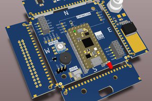
 rob
rob
 Jackson Keating