 Alexander Williams
Here are all the components included with the v.03 kit (without the board):
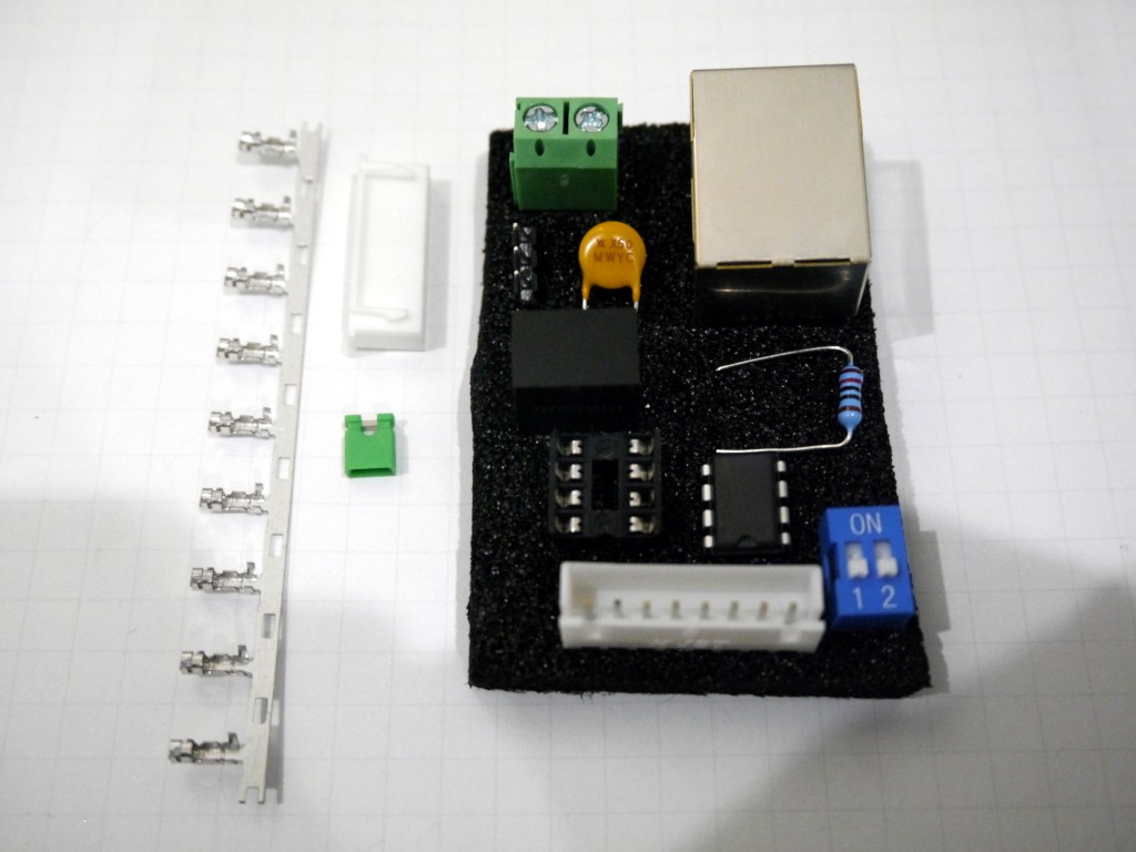
In total there's exactly 40 solder points, and there's a recommended order for soldering the parts which I'll explain in the provided documentation.
The 120ohm resistor is optional, depending on the setup of you modules/system. The 3-pin 2.54mm male headers, DIP switch, 8-pin JST-XH header, and 2-pin screw terminal are also optional depending on how you want to connect/use the module. The fuse is rated at 500mA (trip 1A) and can be swapped for a larger fuse if more current will be drawn. The 5V switching regulator is rated at 1A and can also be swapped for a larger one. Finally, the RS-485 transceiver (MAX3088) can be replaced with another one that's pin compatible (ex: MAX3085) but check the datasheets to ensure the pinout is the same.
I can expect to put the board and kit up for sale on Tindie within the next 3 weeks - assuming all goes well with the v.03 boards.
Discussions
Become a Hackaday.io Member
Create an account to leave a comment. Already have an account? Log In.