 Alexander Williams
If you look carefully at the v.03 schematic, there's a silly mistake I introduced which could be disastrous if the end-user is not careful with their wiring and setup.
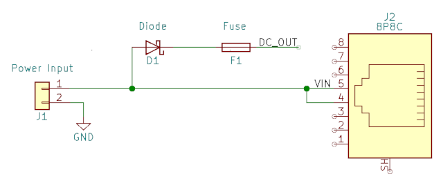
Let's first illustrate the Input current flow on the new v.04 module:
Unprotected Power -> Diode -> Fuse <-> RJ45 / DC-DC Converter
As you can see, the unprotected power, perhaps from a power adapter or bench supply, will first pass through a few components before going out the RJ45 cable, thus protecting it from shorts and overcurrent scenarios. The diode should also protect the power sources, should there be a power source at both ends.
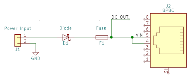
Now let's look at the Input current flow on the old v.03 module:
RJ45 <-> Unprotected Power -> Diode -> Fuse -> DC-DC Converter
Do you see the difference?
What this means is, in the old v.03 module, unprotected power will flow directly through the RJ45 cable to the other module, without any fuses to protect the cable. Any short or overcurrent will flow freely through the cable and likely heat, melt, and burn it down.
I noticed this problem when I first designed v.03, but it was already being produced and I could only hope to correct it in v.04 - which I did.
Hopefully nobody made the mistake of 1) drawing too much current through the RJ45 cable, 2) powering both modules at the same time with the VIN enabled jumper set, 3) creating a short / over-current situation.
As usual, since this is an open source project, I take no responsibility for any problems that may occur with your use of this PCB or design files. Create and use at your own risk.
Discussions
Become a Hackaday.io Member
Create an account to leave a comment. Already have an account? Log In.