 Alexander Williams
Resistors in El Cheapo
While running more tests on the v.04 module, I discovered another issue which wasn't immediately obvious.
On the internets, the below schematic is quite popular:
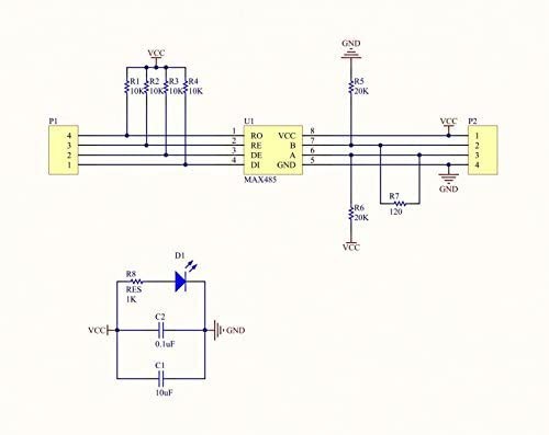
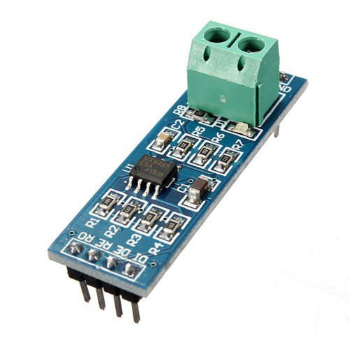
It's a schematic for the ultra-low-end RS485 module using the MAX485 IC, you can find it on Amazon/eBay/AliExpress for like $2 or something.. remember "El Cheapo":
Well, there's more to that story.
Copying garbage
When I first created this project, I copied that schematic's design and integrated it to my module. That was a big mistake because it had some bad engineering implemented on top of the bad physical shape:
- Every data line is pulled high with a 10K resistor - even the outputs. This means the module itself is set as a "driver" by default, and you know what happens when you connect two RS485 drivers together? bad things.
- There is a 120 ohm terminating resistor on the A+ & B- lines. This means your bus is limited to only TWO (2) of these modules unless you desolder that resistor from the other modules.
- There are 20K fail-safe biasing resistors on the A+ & B- lines. This means the voltage drop will be too large (because there's also terminating resistors) and the 20K resistors will be useless - in fact, they won't even do their job of bringing the differential voltage between A&B higher than 200mV when there is no driver on the line...
- ... However, because the receiver output (RO) pin is already tied HIGH by default (10K resistor), the above point is moot.
Isn't that ironic? The board is poorly designed yet it magically works thanks to that poor design. Even more hilarious is that I copied it in my v.03 modules and it also worked perfectly!
Confused? Here's more details
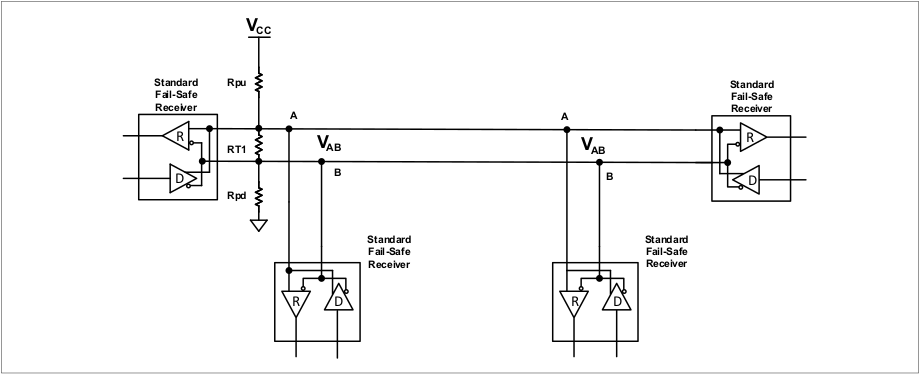
Older RS485 ICs had very basic "fail-safe" feature where the RO pin would go HIGH when the input pin is left floating or shorted. The RS485 IC's fail-safe feature took care to place that pin HIGH when the voltage difference between the A+ & B- lines are greater than 200mV (that's how it detects "high" or "low" on the A+ & B- lines). Unfortunately that assumes there are no terminating resistors between A+ & B-. For that reason, people used to place "biasing resistors" on the A+ & B- lines. The resistors would be identical, A would tie the resistor to +5V (the MAX485 runs at 5V) and B would tie it to GND. Doing so creates a voltage divider which - depending on the size of the resistors - can keep the voltage difference between A+ & B- above 200mV.
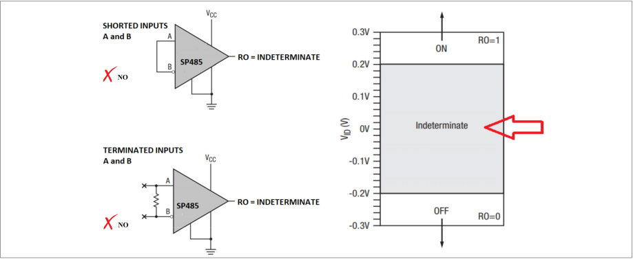
(source: MaxLinear AN291 PDF)
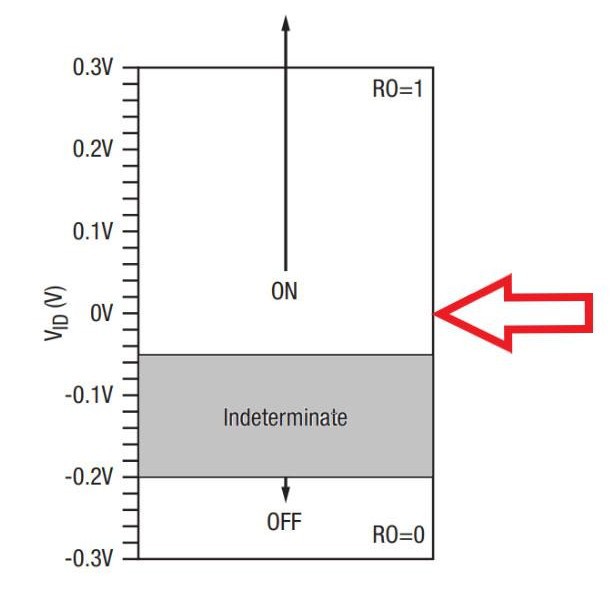
Anything between 200mV and -200mV falls in the "indeterminate" zone: no-man's land for data signals, where the receiver is uncertain if it's seeing a 1 or a 0.
When you use terminating resistors on the RS485 bus (one at each end - max 2), assuming 100 ohm terminating resistors between the A+ & B- lines, and RJ45 (cat5e?) wiring, the voltage will drop significantly. Remember, it should be +/- 200mV, however with the above El Cheapo, basic math shows it would be between 0mV and 15mV. Oops!
But El Cheapo works, everyone uses it!
Actually no it doesn't work. The only reason "it works" is because to make it work, we always tie the pins to an MCU, and we always ensure the proper pin (input/output) direction, and we always use twisted wires between A & B, and we always ensure to only have ONE (1) driver on the bus, and we always only ever use 2 modules on a bus.
So in an ideal wiring situation, all is well. However it will go to hell if you try to use more than 2 modules, or if you decide to set both modules to receive (pull RE and DE down to GND). The voltage difference between A+ & B- in that case will fall too low, moreover the 10K pullups on the data pins will contribute to overloading the bus - which is somewhere between not good, and bad... now, tell me "it works". Hah!
Solutions
For the eagle-eyed, you may have noticed I wrote "Older RS485 ICs". Newer versions of these ICs such as MAX3088 used in the v.03 module, have a differential voltage threshold between -50mV and -200mV. This is much more sensitive, and allows for better handling of "fail-safe" conditions on the bus. It also eliminates the need for biasing resistors on the A+ & B- lines.
(source: MaxLinear AN291 PDF)
Many forum/reddit/stackexchange posts claim "you don't need resistors" on your RS485 circuit, but that's only true if the differential threshold is +200mV to -200mV and/or the IC doesn't have fail-safe capabilities for terminated receivers (i.e: older ICs).
Another alternative is to continue using older ICs such as SP3485 (or MAX485), but to properly calculate and use pullup / pulldown resistors as needed.
The math for that can be found in the MaxLinear AN291 PDF (RS-485 Advanced Fail-Safe Feature Application Note) and the TI slyt324 PDF (RS-485: Passive failsafe for an idle bus) documents.
In the v.04 module, I followed my own intuition for designing the RS485 circuit, and made a few mistakes in my resistor selection (note: i didn't do the math) and that backfired. I also switched from the MAX3088 (5V) to SP3485 (3.3V) whose differential voltage threshold is +200mV to -200mV. In v.05, I will fix this with the following changes:
- Remove the 10Ks resistors on the DI and RO pins.
- Remove the 10K pullup resistor on DE/RE pin (I previously mentioned 4.7K but in fact it's not needed).
- Populate the A+ pullup and B- pulldown biasing/fail-safe with ~430 ohm SMD resistors (we're aiming for ~300mV differential voltage).
- Populate the terminating resistor with a 100 ohm SMD resistor.
- Add a DIP switch or jumper headers to easily enable/disable the terminating and biasing resistors.
With these changes, it will be possible to use more than two (2) modules on the same bus by selectively enabling/disabling the terminating/biasing resistors of each module.
This should work, theoretically, but I'll confirm once I receive the new PCBs.
Stay tuned!
Discussions
Become a Hackaday.io Member
Create an account to leave a comment. Already have an account? Log In.