-
New board
11/24/2023 at 12:43 • 2 commentsFuzix
Unfortunately, the 128KB RAM is too little for the system to run Fuzix. In theory, I could change the board a bit and swap the 32KB RAM chips for 512KB RAM. But every time I looked at the wires at the back of the board, I'm too afraid I will permanently damage the board. So, I give up...
Then I thought, let's make a new board with 2x AS6C4008 RAM chips based on the old design. It was easy to make the schematic in Kicad, but I thought it was an automated process to design the PCB from the schematic. How mistaken I was! In the PCB editor, I got stuck with a rats nest, and couldn't design a decent PCB. So, I gave up again...
Then again, someone must have designed a tiny and simple(!) 68000 PCB board with just RAM, ROM, and a UART without fancy components. Searching the internet and I found this: 68K-nano by Matt Sarnoff. This is exactly the design I was looking for!
68K-nano
I ordered and built this board, and it works fine for me. Made two minor changes:
- AT28C64B for EEPROM; these are in stock with me and pin compatible with the AT28C256.
- Added an 11.0592 MHz crystal to the UART; now it is easy to change the CPU clock speed without altering the divider in the BIOS.
This board runs stable at 24MHz (!) (Matt rated this at 12 MHz). I am now porting my BIOS to this board. After that, I can proceed the Fuzix port on the new board...
-
How fast can it run?
11/24/2023 at 10:56 • 0 commentsIntroduction
Back in the nineties, I was worried if the system could run on 8 MHz. In the end, it did, but now I am curious about what the max speed is. The CPU is a MC68HC000 CPU rated for 16 MHz, but it is unlikely to reach that. The components are pretty slow; the RAM has a speed of 120 ns, and the EEPROM is even slower with 150 ns. The UART and the VIA are old 6800 components and the glue logic is a mix of LS and HCT logic.
Bypass
To test the maximum speed, I had to change the oscillator circuit. Normally, the output of the crystal is divided by two to get an exactly symmetrical output. The is that the crystal runs twice the processor speed. So for an 8 MHz CPU speed, a 16 MHz crystal is needed. And with simple HC(T) logic, you can't go much faster than that. So I soldered a switch to bypass the divider; the CPU runs at the same speed as the crystal.
Testing
So, I tried:
- 8 MHz: check
- 10 MHz: check
- 12 MHz: check
- 16 MHz: check (!)
- 20 MHz: check (!!!)
- 24 MHz: fails
So, the old system runs stable at an astonishing 20 MHz!
How is that possible? Well, the 68000 spends 4 clock cycles for reading/writing a 16-bit word. The successor, 68020, uses only 3 clock cycles, so you could say the 68000 has a built-in wait state. The clock for the UART and VIA is divided by 10, so 20 MHz leads to a clock of 2 MHz, which is the upper bound of the capabilities.
It is amazing that the old system runs so fast!
-
Porting FUZIX
02/04/2022 at 16:50 • 2 commentsIntroduction
Wouldn't it be nice to have a proper and working operating system running on this board? I've looked for Minix, but that way to large and complex. Then I read about FUZIX. It is a unix "like" operating system designed for old tiny 8 bits systems with a Z80 or 6502 CPU, and is ported to all kind of single board computers including MC68000! It is even ported to the Raspberry pi pico!
All the hardware is driven by FUZIX; the BIOS is only used for starting the system. The most interesting is, it has a build in (unix like) filesystem.
System requirements
- Some kind of IO (serial will do) > check.
- The operating system occupies about 64K, I have 128K > check.
- Reoccurring interrupts (100Hz) for scheduling and multitasking; I have a programmable timer+IRQ > check.
- Some kind of storage; the system is has a (very slow) interface for SD-card > check.
- Optional RTC; the system is connected to a DS1307 RTC > check.
- Free programable vectors (trap #12 used for calling the system). Oops; the ROM is mapped from 0x0000 to 0x4000; all vectors are fixed. But is this really a problem? Of course not; the BIOS is owned by me and I can easily reroute trap #12 to ROM, and use an RAM address for jumping. Just need to change the vector address in fuzix > check.
But on the other hand; this will be a major project...
Tool chain (Jan 2022)
The first thing before you can even think of porting this, is a tool chain. That's not as simple as it looks; you need a m68k cross assembler/linker/compiler and they are not common these days. First I tried serveral LINUX scripts and virtual box, but that didn't work for me; all kind of errors I couldn't handle. Then I found on Rosco's Rosco's page a m68k gcc toolchain installed from home-brew; that worked like a charm on a Macbook and Mac mini! Easy to install and the compiler, linker and assembler were working at once!
Geek... it compiles! (Jan 2022)
After downloading FUZIX from git it got really exciting; I expected all kind of compiler errors, but it compiled without any error! Of course it isn't working but for me this is a big moment to decide to go further. I have a Fuzix.ELF file which easily can be converted to a S19-file. I even got the addr2line util working; tip it needs a "-f" option to work.
First steps (Feb 2022)
After changing lot of assembly coding for TTY and SD-card it now shows -without crashing- fuzix' start text and detects the SD-card. Also the 100Hz clock interrupt are on. The next step is to create and mount the filesystem.
Out of memory (march 2022)
Since the last update I made some progress:
- Updated the BIOS for rerouting trap #12 through memory.
- Added tty input (so I can enter bootdev "hda1".
- Created the whole disk image by compiling all the provided stuff and wrote it to a SD-card. (It could compile all but one file: the find-util).
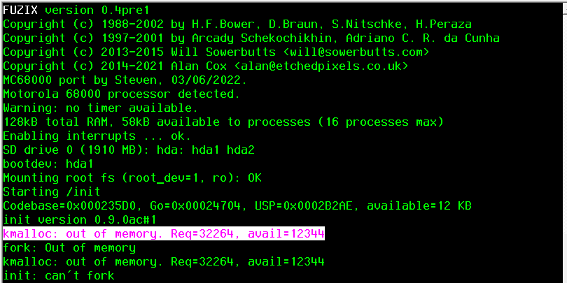
Fuzix stopped with the message "No /init". This can mean anything; no filesystem, wrong filesystem, no access rights, wrong file type, wrong relocation information etc. After some debugging it turned out that the system is out of memory. After reducing the disk buffers from 16 to 4 (that saves me 6 KB) it started /init. But then again out of memory. Init is forking itself and needs another 31 KB.
Of course I can remove some unused device drivers from the kernel, saving me some extra KBs, but the gap is at least 20KB. I am afraid the 128 KB is not enough for a 68000 system to run :-(
I really have to think about heating up the soldering iron and add more memory to the system...
Found some memory (March 2022)
After investigating the system, I found a lot of wasted memory:
- Every process gets 16kB stack (elf2flat -s 16384); I reduced this to a configurable max 1kB.
- Reduced (temporaly) the disk buffers from 16 to 3 (freed 7 kB).
- Reduced (temporaly) the number of processes from 16 to 5 (freed a few hundreds bytes).
- Removed unused device drivers (ZX-keyboard, quart cart) which gave me some extra kB.
- In execv32 the load process reserved temporaly memory for the relocation information. In uses the bss-segment and increase this if necessary, but didn't use the stack space. Just a simple change in the calculation saves again several honderds of bytes.
After loading Fuzix it I have 71kB free; 23 kB more than before.
Address error (March 2022)
This nasty address error was shown after loading the shell; the PC is on an odd address (02C4A1). This kind of errors are very difficult to track down, because you can't use the PC and find the routine in which the error occurred.
Usually the stack is overwritten (so I enlarged the stack > nope).
The error was very stable, always the same address and the same moment, so it seemed not related to the interrupts.
Entering debug statements is an option, but this means edit source > compile > make diskimage > write diskimage to SD > place SD to system > start Fuzix and see how it works. Because al these steps takes time the turnaround time are several minutes.
After debugging it seems to go wrong in the source of shell: Applications/V7/sh main.c > name.c (assnum()) > print.c in "itos()". This is a very simple routine for converting an integer to string. The 32 bits devision (in 68000 not available so the compiler has to call a subroutine for it) went wrong! After changing type "int" to "uint16_t" it worked fine.
-
Reflashing the BIOS
11/07/2021 at 18:35 • 1 commentBack in the old days EPROMs were used to store the BIOS. To erase them, you need UV light. I used a sunlamp for that, but I havn't got that one anymore. Besides the procedure to erase them was a bit time consuming, which increased the turnaround time of developing and testing. So I was looking for a better replacement.
I found that the 27128 EPROM (16kB) could be replaced by a AT28C64(B) EEPROM (8kB), without changing the circuity.
The tool chain I used in 1991 was MS-DOS based and ofcourse completely outdated. some parts were self written in turbo-pascal. To set up a new one, more future proof, I wanted to be abled to use it as well on windows as on MacOS, perferably open source. And it should be compatible with the old sources too. For now I am using:
- EASy68K: as simulator for testing routines.
- vasm: assembler to assemble the 68k mnemonics to S19 (hex) file.
- src_cat: convert the motorola S19 hex format to Intel hex, and to split the file for the two EPROMs (odd and even).
- TL866plus: programmer & software to program the EEPROMs.
...and after thirty years, the new BIOS is flashed!
![]()
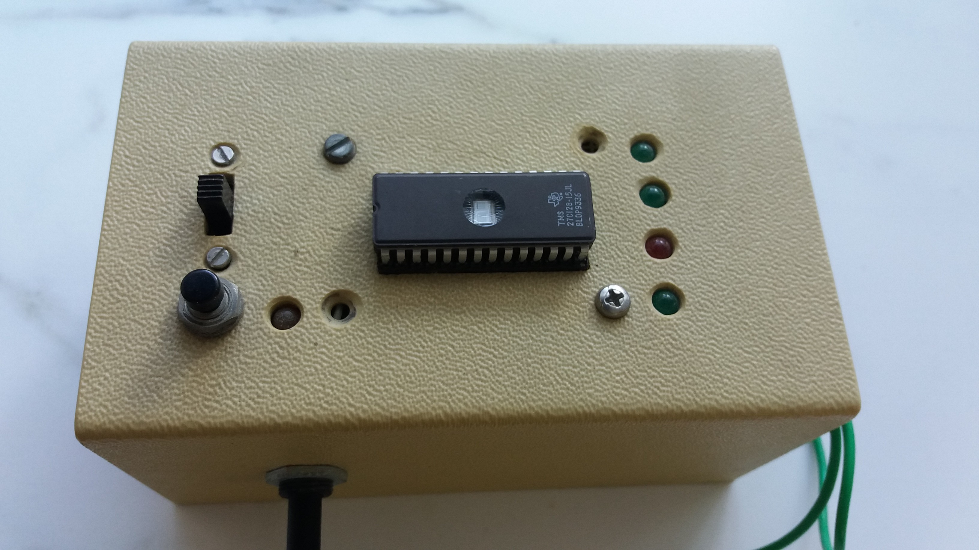
This is the programmer my brother build to program the EPROMs, I wrote the software in turbo-pascal. Data was send by the parallel/printer port. In the box there should be a counter and latches, to program the chips. It's amazing what we build ourselfs those days...
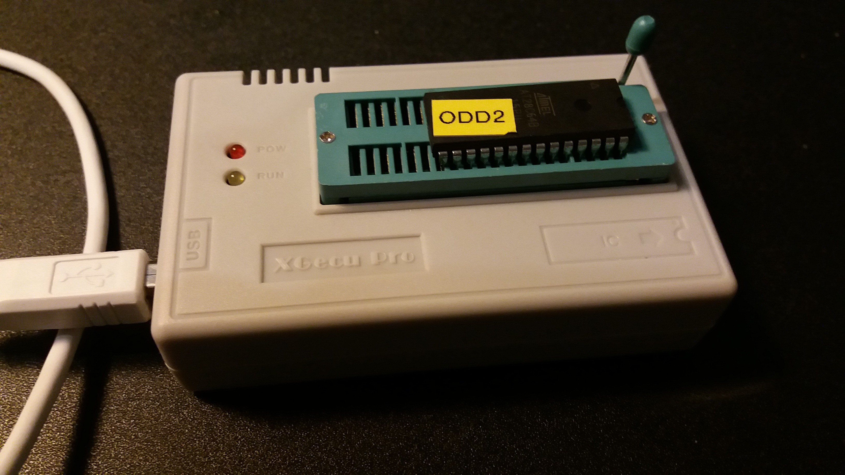
Now I am using this little box (TL866 plus) which is cheap to buy and very functional. Even the old EPROMs could be programmed and it is easilly connected by USB. The software runs on windows but I read it should also also run on linux under wine.
![]()
-
Reducing power
11/06/2021 at 18:16 • 0 commentsMonth ago I bought two CMOS replacements for the CPU: MC68HC000. The advantage of this CMOS CPU is that it consumes less power. Unfortunately the replacement was not that simple as you think. The replacement came from China and were used chips. They were desoldered and some of the pins were bent. But after some gentle wiggling I managed to get all the 64 pins in the right holes...
The current in the system drops from 480 mA to 280 mA, so a reduction of 40%.
Besides the power consumption and therefor a lower temperature, there are no advantages for this chip. In the old days I had a PC with the CMOS replacement of the INTEL 8080, the NEC V20. This CPU was 25% faster on the same clock speed as the original. I remembered that all the chips on the board were warm, but the CPU keeps cool.
-
Dusting the project
05/16/2021 at 14:16 • 0 commentsI hadn't looked on to it for years (no time, creating an extra room in the attic and so on), but it kept itching... On the other hand it seems so strange fiddling around with old hardware, a simple ESP32 has more capabilities and speed than a 68k will ever have.
Two reasons for dusting 1) I found out you could still buy very cheap (used) spare parts like 68000 chips (in China) and 2) I found this (and other sites) where many people greb their soldering iron and creating all kind of old and new -cool- hardware projects. And wouldn't it nice to combine this old hardware with new and very cheap hardware like SD-cards, RTC, 1-wire temp sensors and so on, like we use to do with Arduino and ESP32?
The board was build in the ms-dos time, with turbo pascal and a cross assembler as main development tool on a XT 8MHz IBM-clone (with by the way I overclocked it to 9 MHz). Since I went away from windows to MaxOs, I have to use (temperately) a virtual Box with 32 bits windows with the necessary tools. The goal is to use as many as possible standaards like VT100 (serial terminal program), Free pascal / Lazarus (as development tool), X-modem (uploading programs), FAT16 etc, so I won't be dependent from specific hardware/software.
Clock circuit
After powering up the board sometimes came alive but always was unstable. I found out one loose wire (for the interrupts) but that doesn't solve all the problems...
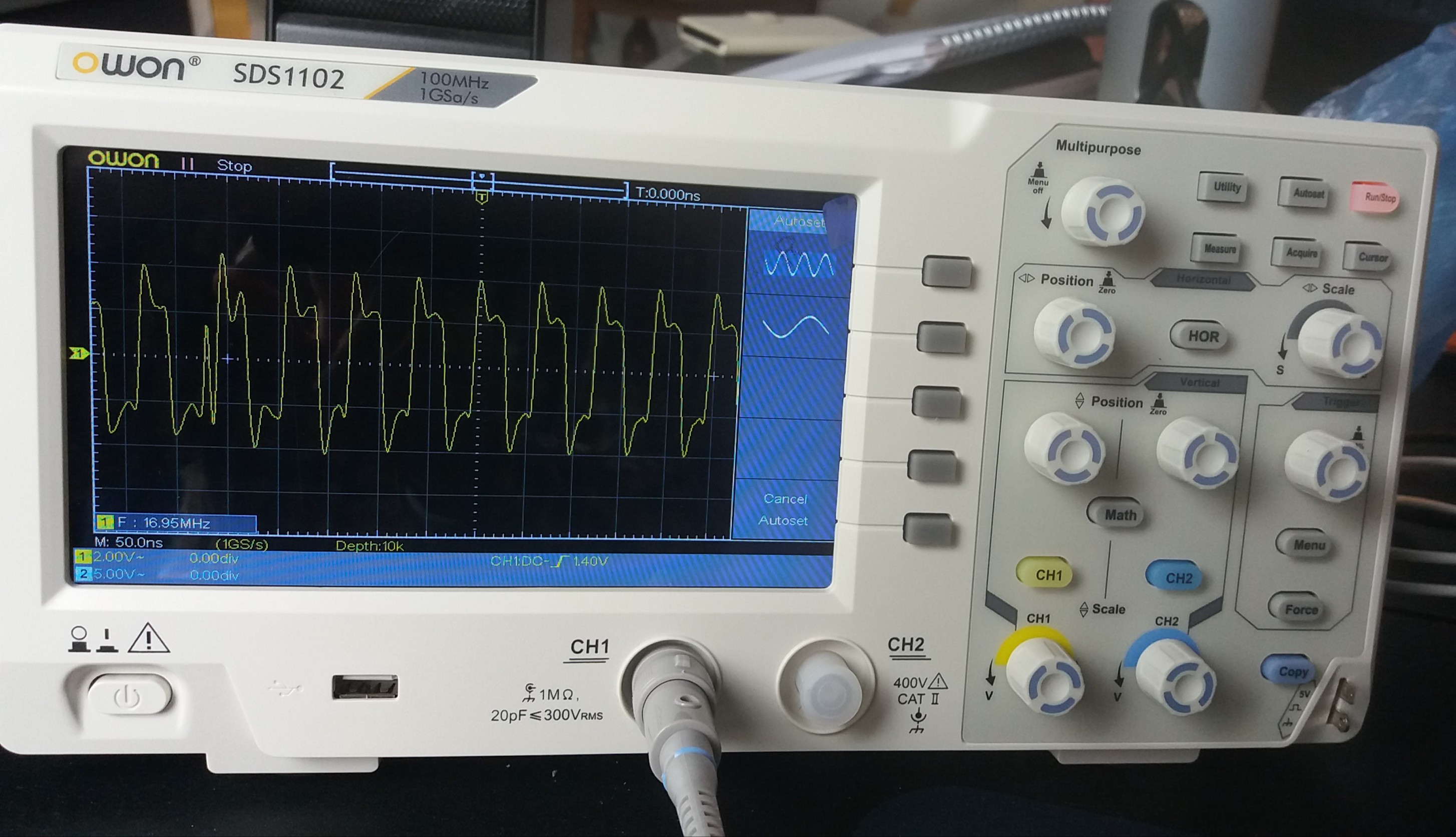
As as student I didn't have an oscilloscope, in those days way to expensive. But this was the moment to buy one! For only about EUR 200 you can get yourself a reasonable one. After connecting it to the clock circuit of the board the problem became clear. On the scope you can see a sneaky spike after the first clock pulse, which let the CPU crash. And also the frequency is a strange 16.95 MHz (bottom left corner) with *every* kristal I used (from 2 till 24 MHz)?
![]()
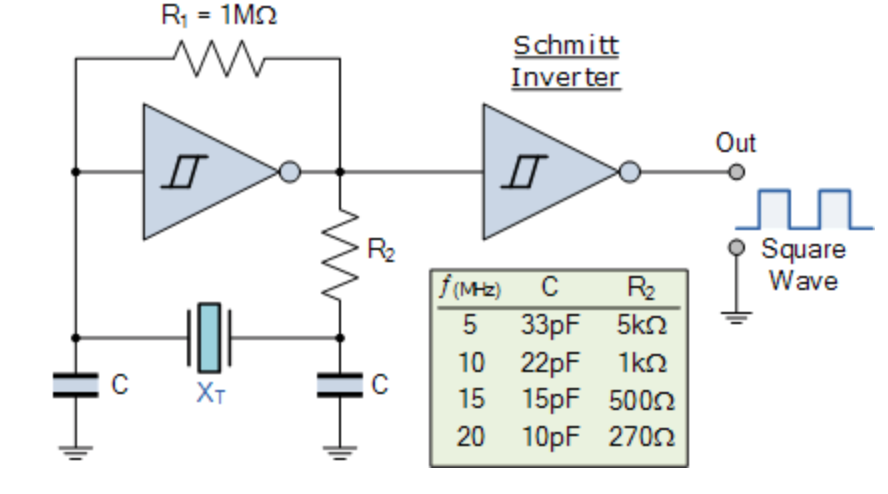
The clock circuit was copied from the one in the XT-pc; two inverters (with a 330 ohm resistor over every inverter) and the crystal between it. Only the circuit was mentioned for LS logic and I builded it with HCT (c-mos). The result is a very unreliable oscillator...
![]()
So I rebuild it to a suitable circuit which worked with crystals from 5 till 24 MHz (ground tone only) using a 74HCT04 and after dividing it by two there is a stable and clean 50% duty cycle clock.
![]()
Lessons learned: never modify a circuit unless you completely understand it fully.

