 Vipin M
Learning about the impact of bipedia on human evolution has been of interest since antiquity - from Aristotle, through Renaissance to present day. In his work, De Motu Animalium as early as 1680, Borelli introduced spring-mass models to understand walking and running in bipedal animals.
To understand some of the control aspects of legged locomotion, the book 'Legged Robots That Balance', 1986 by Marc Raibert is a good starting point. Turns out that there is a ton of physics and math behind these robots. So, I spent a couple of days reviewing some of the key concepts like kinematics, dynamics and control but could barely scratch the surface.
Eager to build something, I picked up a paper by Disney Research where Gim et all propose a design of a hybrid leg for a bipedal robot that combines both serial and parallel mechanisms to achieve 6 DoF. The unique design allows the leg to achieve small inertia and large workspace while retaining the anthropomorphic structure of a human leg.
Design
Each leg consists of 2 serial chains connected together at the ankle. Each chain uses a 5-bar linkage for generating the pitch motions at the hip and knees and a roll joint at the hip. Together, this setup is able to achieve 6 degree of freedom, 3 in each chain with 6 actuated joints and the remaining as passive joints.
I started off by designing the hybrid leg in Fusion 360. Had to go through a couple of revisions because of the weakness in the ankle joint that would cause it to break or have excessive play during testing. I built a single leg first to iron out any mechanical or software issues. Once the leg was working as desired, I printed a mirror version of it as the second leg. The entire leg assembly stands about 1 ft tall and measures around 3.3 lbs.
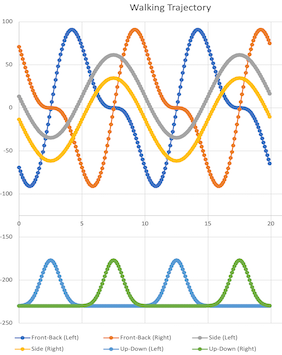
Trajectory
The trajectory was generated manually with independent sagittal and lateral movements.
 |  |
Analysis
To simplify the analysis of mechanical operation and coding of the control logic, the parallel linkage for a single leg was split into multiple kinematic chains:
| Chain Number | Links in the kinematic chain |
| Chain 1 | {L1_0, L1_1, L4} |
| Chain 2 | {L1_0, L2, L3} |
| Chain 3 | L1_0, L2, L6} |
Each link in column 2 above is described by 2 joints that it connects. The joint definitions are given in the table below.
| Link Number | Joint 1 | Joint 2 |
| L1_0 | Roll joint at the hip | Pitch joint P2 |
| L1_1 | Pitch joint P2 | Pitch joint P4 |
| L2 | Pitch joint P2 | Pitch joint P3 |
| L3 | Pitch joint P3 | Pitch joint PE |
| L4 | Pitch joint P4 | Pitch joint P5 |
| L6 | Pitch joint P3 | Pitch joint P6 |
I then identified the Denavit-Hartenberg parameters (d, theta, r, alpha) for these chains as follows:
Forward and Inverse Kinematics

The following expressions are used to calculate the angle 'θ3'. Position of different endpoints can then be determined through forward kinematics. In the code, it is used to initialize the legs to their starting positions.
To calculate the joint variables using inverse kinematics, the following expressions are used.
Unit Testing
| Prior to testing the desired gait, unit testing was performed on each leg to ensure that the calibration was correct and that all the motors were functioning as expected. As such, a unit test framework was developed to test some simple trajectories The adjacent image shows the testing of front to back movement of the 2 legs. |  |
| This image shows the vertical movement of the 2 legs. |  |
| This image shows the side to side movement of the 2 legs. |  |
Limitations
- From the control perspective, only static gait was attempted. Sensors will be needed for dynamic gait.
- From the mechanical perspective, no dynamic analysis was done. The stall torque of the motors was sufficient to support the weight of the leg in the upright position. However, they were not powerful enough to support the weight during motion. As such, the whole mechanism had to be supported using strings during the motion to reduce the weight.
 Aaed Musa
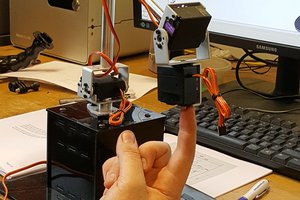
 Yannis
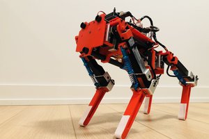
 Lingkang Zhang