 vincentmakes
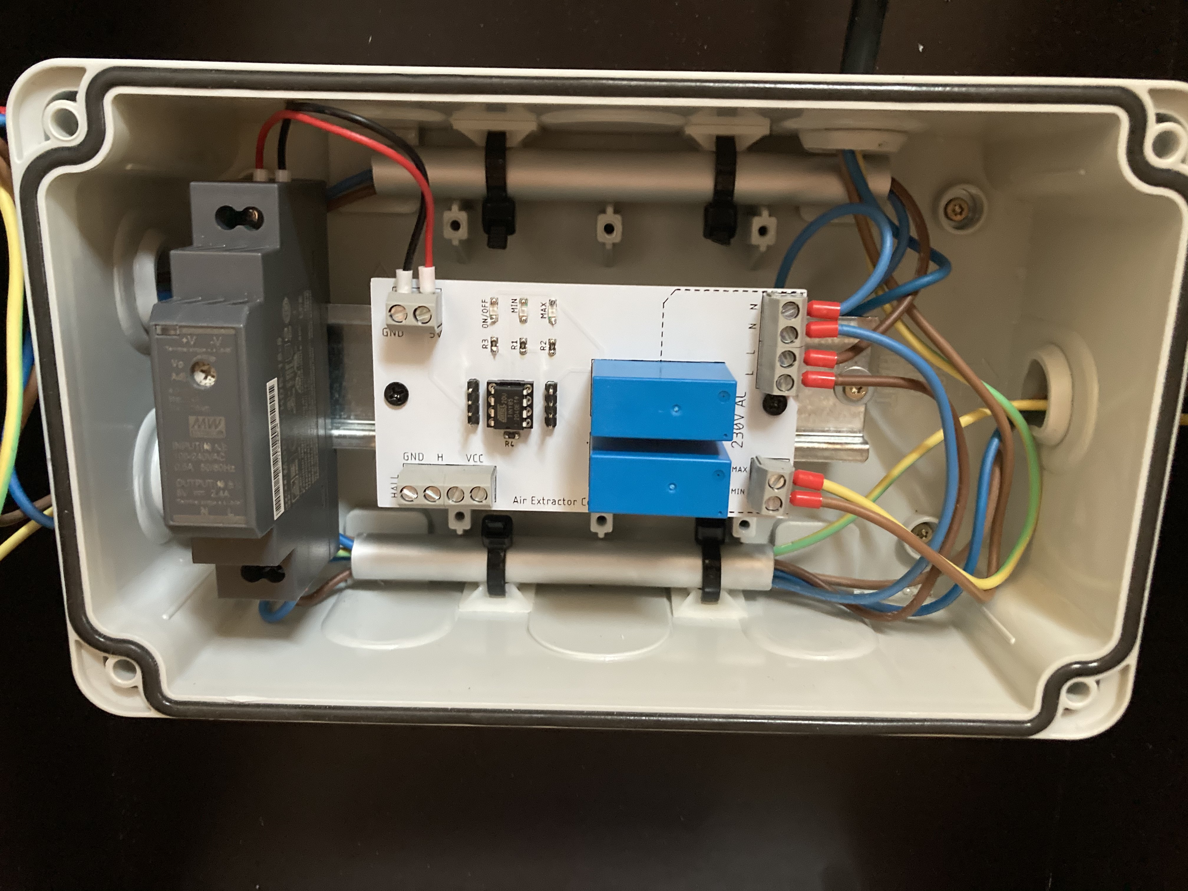
I received the PCB, soldered the components and installed everything into the enclosure.
This is when I realised I was missing a connector for a 3rd N cable on the PCB but that was solved easily outside (and stuffed behind). I will correct that on the schematics and PCB printout.
I mounted the PCB on one of those DIN mount from Delock and installed it on the rail along the 5V DIN power supply. I also just got a crimping tool and got carried away:
I still didn't get the hall effect sensor so I can't test everything together.
However, my next step is to do a dry run where I simulate the AC. In order to do that, I have modified a little bit the production sketch to run the following sequence:
Air extractor Off -> 5s -> Min Speed 5s -> Max Speed 5s -> Off 5s -> etc.
The purpose of this SIT is two folds:
1. Test if what I've done actually works without worrying about the sensor itself which has its own challenges
2.Test if the Attiny85 has enough computing power. I will feed it a fake value to calculate the RMS value and see if it can keep up as calculating a square root is a greedy process.
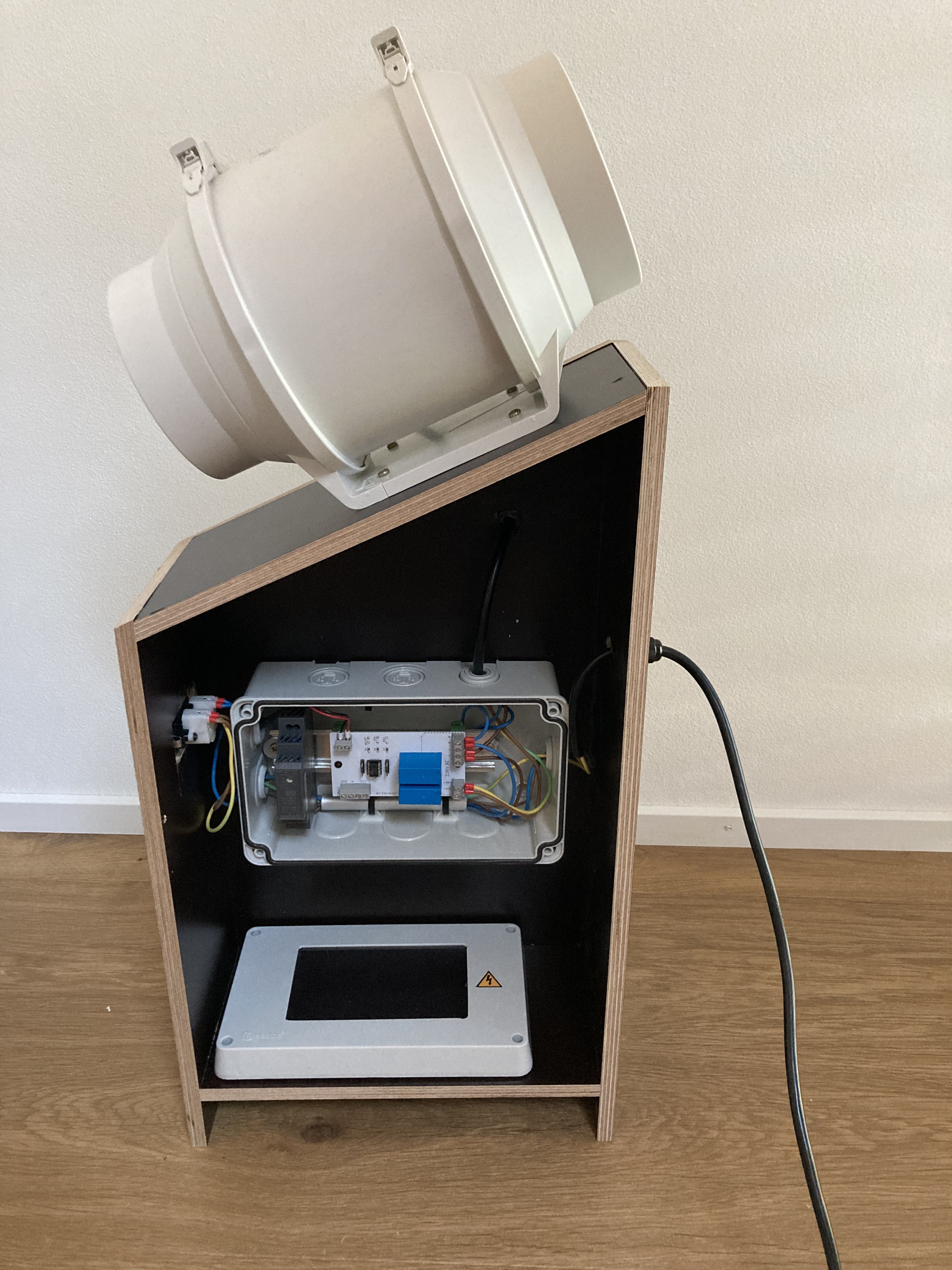
The whole assembly:
Discussions
Become a Hackaday.io Member
Create an account to leave a comment. Already have an account? Log In.