Subhajit
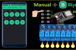
In this IoT project, I have shown how to make IoT-based Smart Home Automation using Multiple NodeMCU ESP32 network to control all the home appliances from the switches & Blynk App.
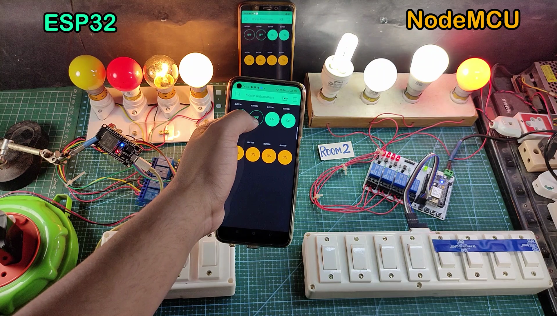
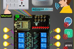
If the internet is not available, then you can control the home appliances from manual switches. During the article, I have shown all the steps to make this smart home system.
This complete Home Automation system has the following features:
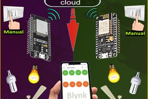
- Connect multiple ESP32 and NodeMCUs with the same Blynk account.
- Control home appliances with WiFi (Blynk App)
- Control home appliances with manual switches.
- Monitor real-time feedback in the Blynk App.
- Control home appliances manually without internet.
- You can connect any number of microcontrollers in this IoT network as per the requirements.
For each room, you just need a relay module & a microcontroller like ESP32 or NodeMCU to make this smart home project.
Required Components:
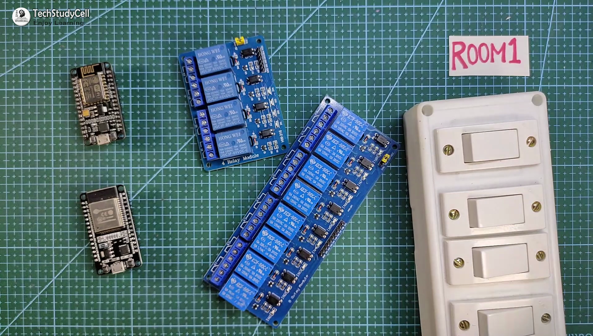
For each room, you just need an ESP32 or NodeMCU, relay module & switches to make this smart home project.
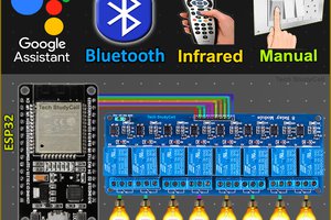
If you use ESP32 then you can use either a 4-channel or 8-channel relay module, but for the NodeMCU you have to use the 4-channel relay module.
Required Components for the PCB:
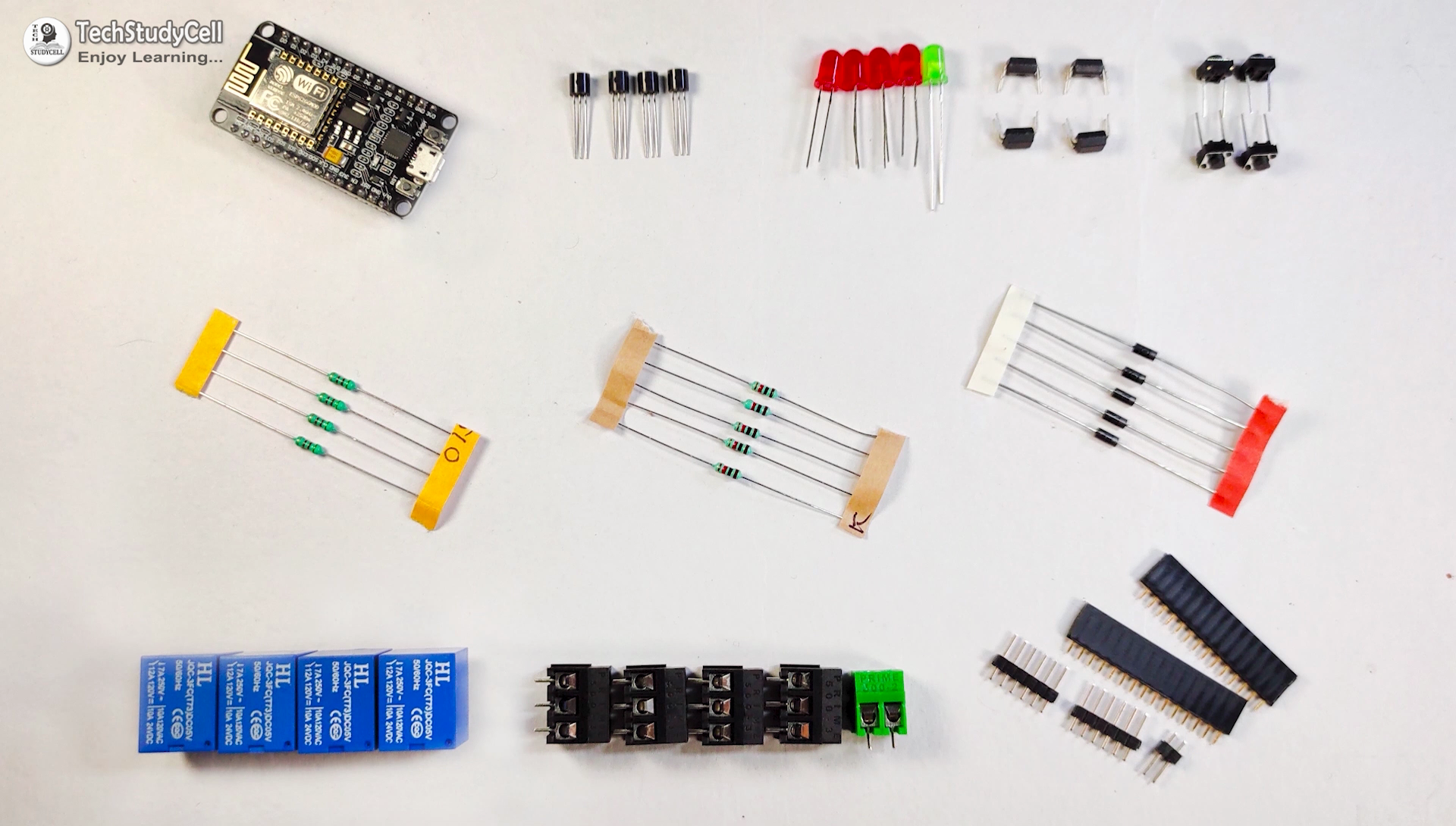
1. Relays 5v (SPDT) (8 no)
2. BC547 Transistors (8 no)
3. PC817 Optocuplors (8 no)
4. 510-ohm 0.25-watt Resistor (8 no) (R1 - R8)
5. 1k 0.25-watt Resistors (10 no) (R9 - R18)
6. LED 5-mm (10 no)
7. 1N4007 Diodes (8 no) (D1 - D8)
8. Push Buttons (8 no)
9. Terminal Connectors
10. 5V DC supply
Required Software:
1. Arduino IDE
2. Blynk App
Circuit Diagram of the ESP32 Control Relays:
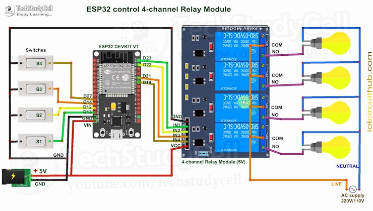
The circuit is very simple, I have used the GPIO pins D23, D22, D21 & D19 to control the 4 relays.
And the GPIO pins D13, D12, D14 & D27 connected with switches to control the 4 relays manually.
I have used the INPUT_PULLUP function in Arduino IDE instead of using the pull-up resistors.
I have used a 5V mobile charger to supply the smart relay module.
Please take proper safety precautions while working with high voltage.
Circuit Diagram of the NodeMCU Control Relays:

The circuit is very simple, I have used the GPIO pins D1, D2, D5 & D6 to control the 4 relays.
And the GPIO pins SD3, D3, D7 & RX connected with switches to control the 4 relays manually.
I have used the INPUT_PULLUP function in Arduino IDE instead of using the pull-up resistors.
I have used a 5V mobile charger to supply the smart relay module.
Multiple NodeMCU ESP8266 Network:

Now if you have multiple rooms, then you can use either ESP32 or NodeMCU for each room and then repeat the same circuit for each room.
If you use ESP32 then you can use either a 4-channel or 8-channel relay module, but for the NodeMCU you have to use the 4-channel relay module.
There is no limitation on the number of ESP32 or NodeMCUs that can be connected. All microcontrollers will connect to the Blynk server using the same Authenticate Token.
So we can control each NodeMCU or ESP32 independently from Blynk App.
Control Relays With Internet Using Blynk:

If the ESP32 or NodeMCUs are connected with the WiFi, then you can control the home appliances from Blynk App.
You also use multiple smartphones to control the appliances with Blynk App. For that, you have to log in same Blynk account from all the smartphones. In this way, all smartphones will be sink to the Blynk server.
You can control, monitor the real-time status of the relays from anywhere in the world with the Blynk App.
Control Relays Manually With Switches:

If the WiFi is not available, you can control the relays from the switches.
The NodeMCU will check for the WiFi after every 3 seconds. When the WiFi is available,...
Read more »