 pkElectronics
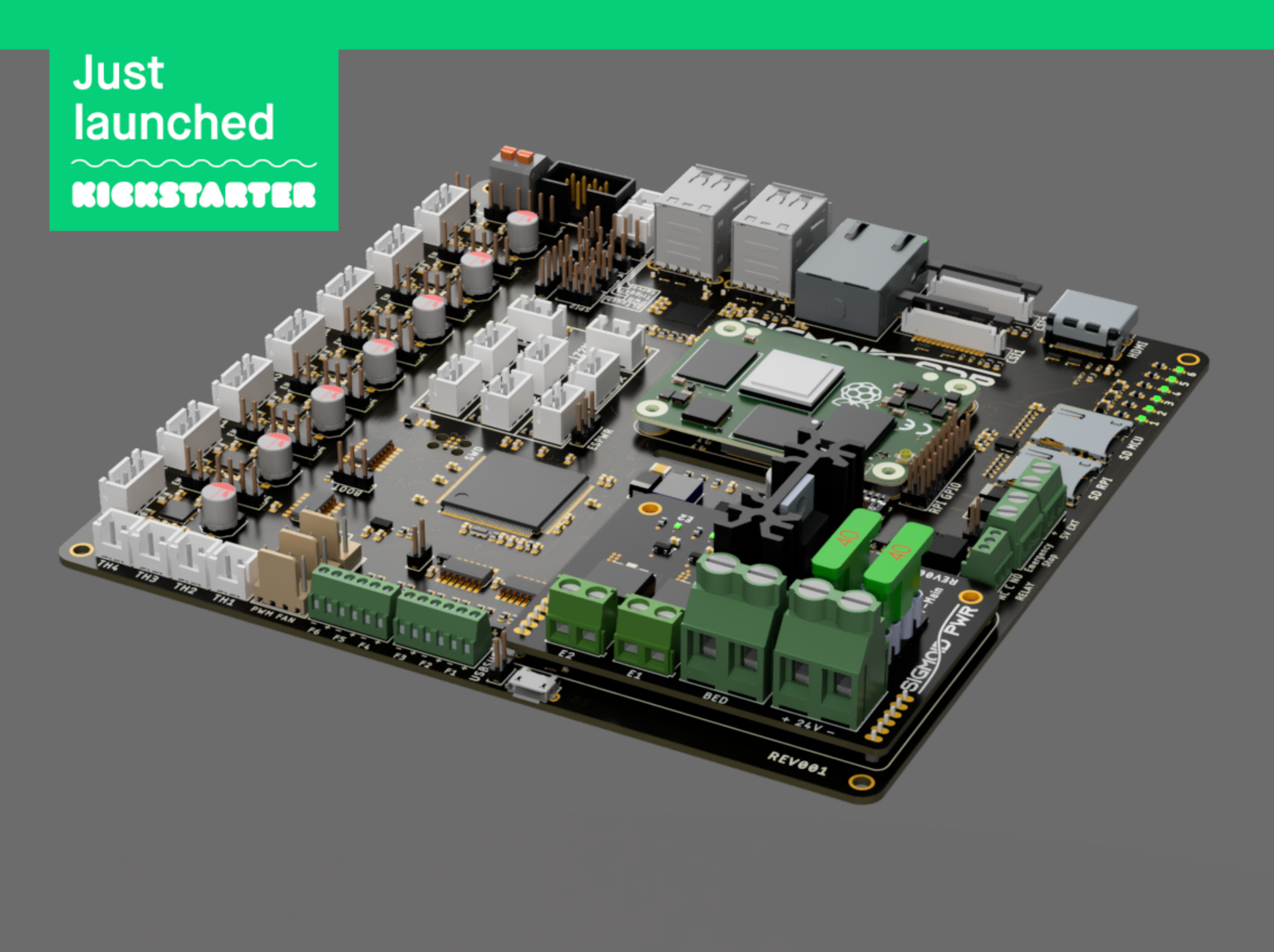
There it is - we are live on Kickstarter
exactly as planned the campaign launched a few minutes ago. Make sure to grab your board as long as the early birds are available.
It´s official - we´re going to make it happen
Over the last few weeks I received lots of awsome and motivating feedback and after double checking a few things and collecting some prices from potential suppliers, I can now announce that we are on track for a crowdfunding campaign to get this board into production. Planned start date of the campaign is July 1st so mark that day in your calendars. Stay tuned :)
How it started...
When I first got the idea of an all integrated 3D printer control board the only option available were the Raspberry Pi Compute Modules in SODimm format but I could not wrap my head around it so it was basically discarded before becoming a concept.
Then in 2019 I visited a workshop from ST about their all new STM32MPU1 and I was: hey, this could actually work. I even started designing the hardware from scratch and then somebody with the same idea came and killed the project because the MPU was not powerful enough to run OctoPrint. So it was postponed again.

But than came the release of the Raspberry Pi Compute Module 4 with it´s all new formfactor and I was back on track because I knew it would not get better anytime soon. So I once again started working on it with a result I´m still absolutely amazed of.

How it was designed
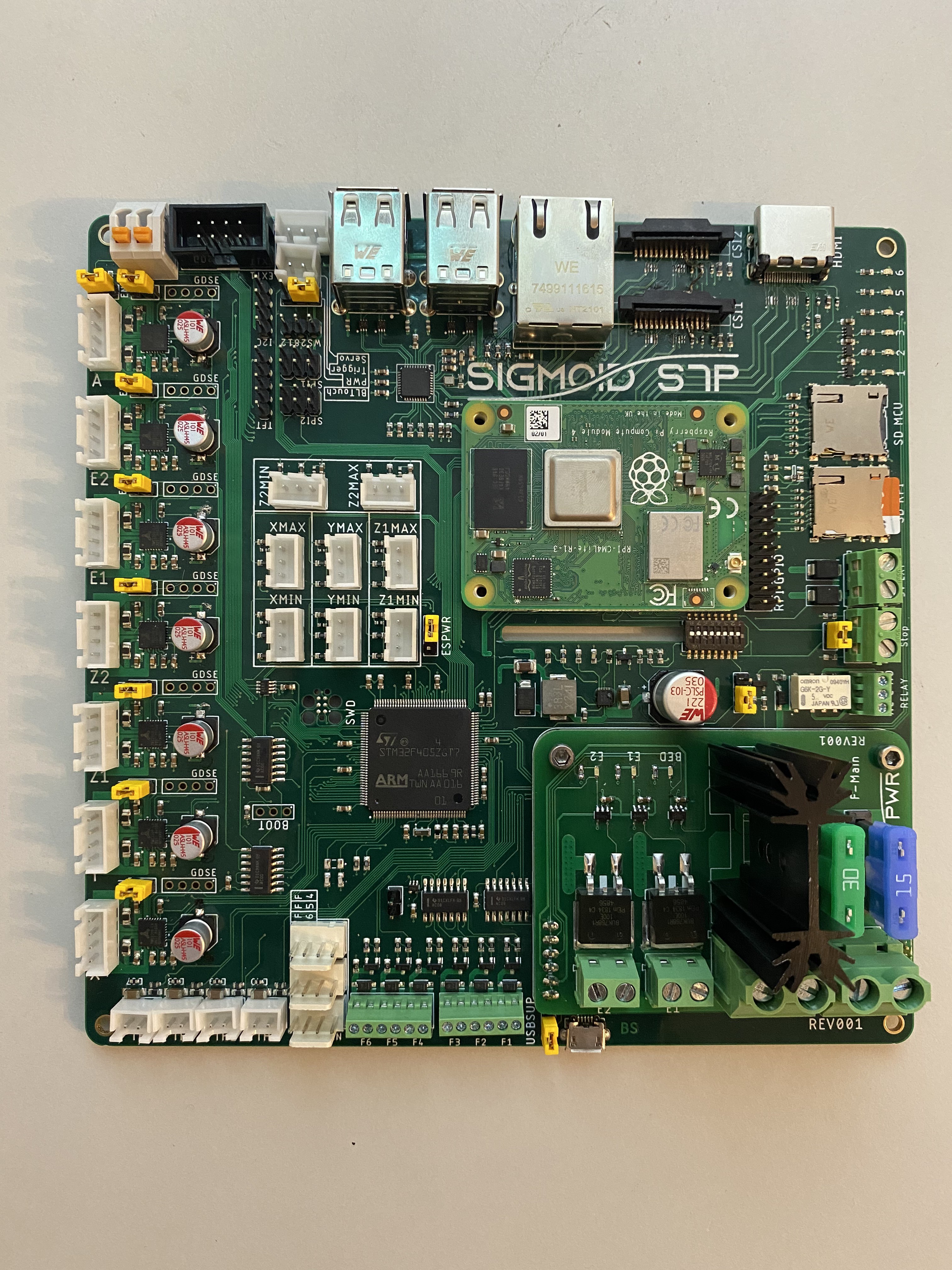
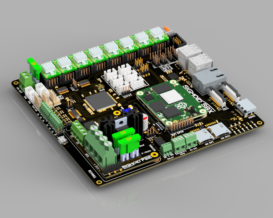
Working together closely with a few friends from the Voron community I figured out the necessary featureset to eradicate most compromises of the boards available today. With the biggest feat being the integrated Raspberry Pi which has almost all GPIO either used or broken out to connectors I put in everything a Voron could benefit of (cause I want one too) and everything I personally didn´t want to miss.
The schematic and board design were done completely in Autodesk Fusion360 within several weeks of sporadic latenight sessions. Several renderings were showcased to german 3D printing communities to check for feedback and additional ideas. Although being something I started for the sole purpose of doing it, I just couldn´t keep it a secret.
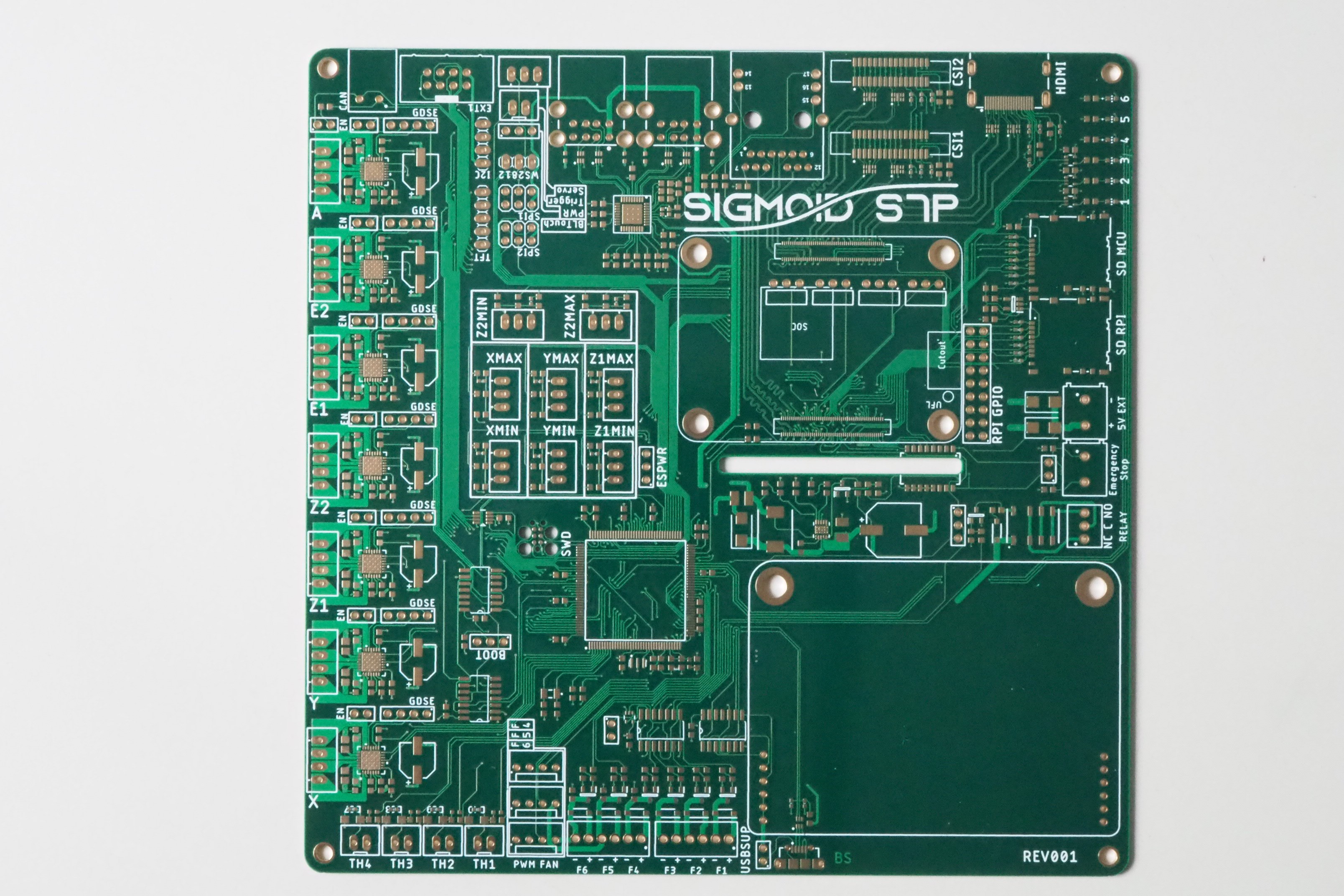
As the nature of the Compute Module requires the developer to handle the highspeed signals like HDMI or CSI by himself and break them out to connectors, impedance and length matching becomes crucial. To get the impedances under control I opted for a four layer pcb and choose the JLCPCB controlled impedance stackup as a design point. The JLC2313 stackup has a prepreg as thin as 0.1mm between the inner and outer copper layers allowing for really thin differential traces even at 90 Ohms impedance.
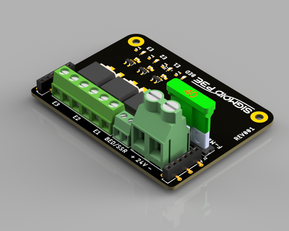
The power switch board was built as a separate PCB so I could get it manufactured with only two layers and with more copper on those layers (e.g. 2 oz. instead of 1) .
Somewhere during the layout and rendering phase I started to heavily dislike the working title of the board. Progress R2 just doesn´t sound good and neither does it written on a PCB, after quite a while of thinking about this I came up with the Sigmoid name and a 3 letter description of the board. The Sigmoid or S-function as eponym to the board acutally makes sense as well. With the Sigmoid function describing the traversal between to equilibrium values, the Sigmoid board basically traverses between the low-level mcu firmware and the high-level software on a Raspberry Pi.
What it can do
| Printing | Connectivity | Misceallaneous |
|---|---|---|
| 7 TMC2209 Stepper Driver | HDMI | Hardware Emergency-Stop circuit |
| 4 Thermistor channels | 2x CSI for Raspicam | User controllable relay with NO and NC contacts |
| 8 Endstop channels | 4 USB 2.0 Ports | 1 CAN bus channel |
| 30A Power MosFET | Gigabit Ethernet | expansion connectors with UART, I2C and SPI |
| 2 Extruder heater channels | WiFi | Car fuses for system protection |
| 3 Generic power switches 3 Fan channels with tachometer inputs | ||
| BLTouch connector | ||
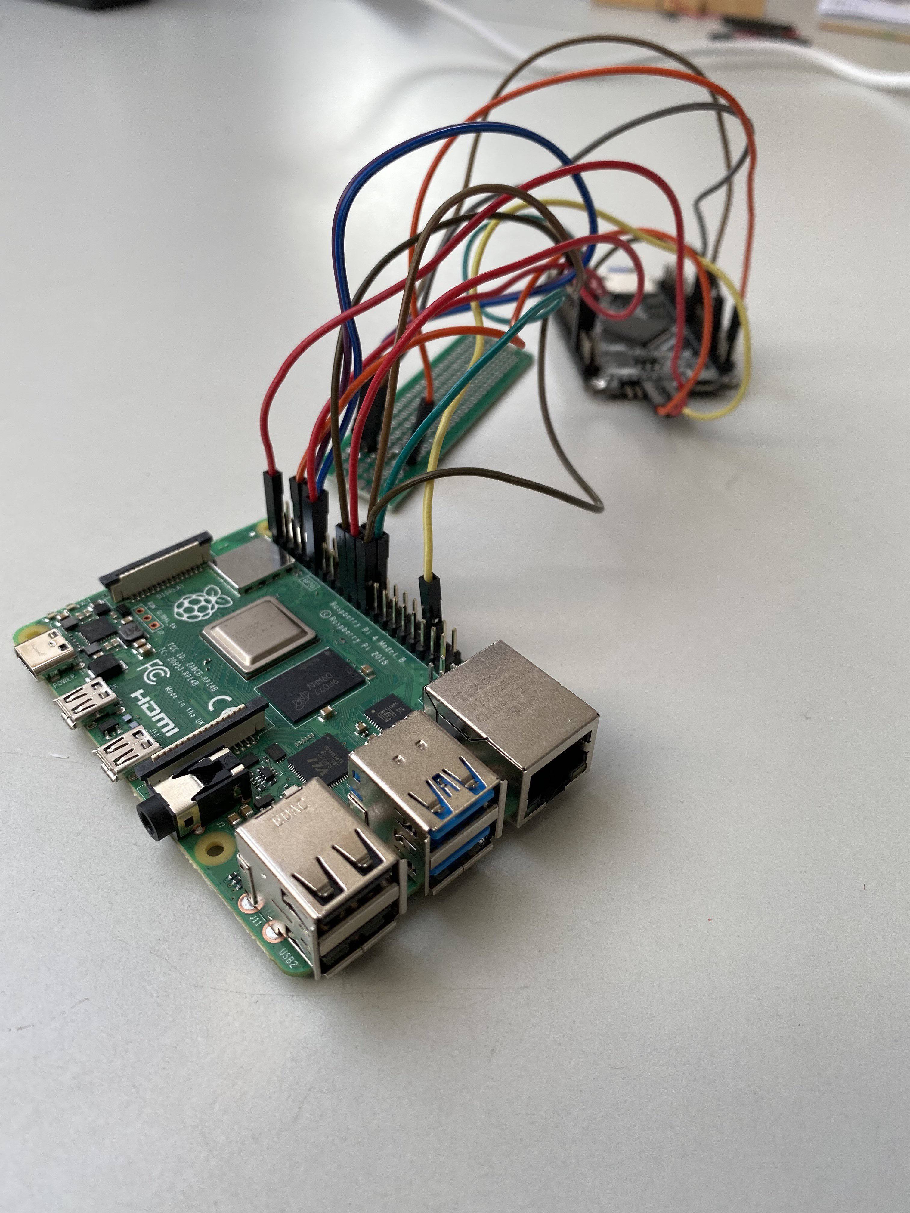
Software support
Generally speaking, everything is supported. I tested the connections required for the different Firmwares to the host prior to the PCB design with a Raspberry Pi 4 and a STM32F407 devboard. To flash the firmware I use the integrated flash bootloader of the STM32 and added dedicated boot and reset lines between the MCU and the RPI. To support the STM32 port of RepRapFirmware and Duet Web Control, I also added an SPI bus connection between the MCU and the RPI.
RRF and DWC2 were actually the hardest ones to get working. The STM32 port is still pretty new and has some edges which I had to polish before I could acutally establish a connection between the RRF and Duet Web Control.
How it´s going
Lucky me was able to persudade JLCPCB into a sponsoring agreement for the PCBs to showcase their capability of building sophisticated high-speed capable boards. Their impedance calculator performed exactly as desired. I can´t measure the signal integrity of the highspeed parts do to lack of equipment but what I can say is, everything works as expected.
Parts were sourced from Mouser, Farnell, RS-Components Würth Elektronik and Berrybase.
Due to the current overall chip shortage this was far harder than anticipated with order getting delayed several times or cancelled completely.
After the first allnighter of assembly and soldering, at least the Raspberry Pi seemed to boot but no output on the HDMI port was existant. Turns out I forget several traces under the esd protection device which was in place on the HDMI and CSI ports, luckily this was easily fixable with a few wires.
The last fail was the enable pin of the second CSI port, which was completely messed up, still don´t know how this could happen.
Up next were several nights of individually testing all the different functions and IO Ports of the board to search for design or assembly errors.
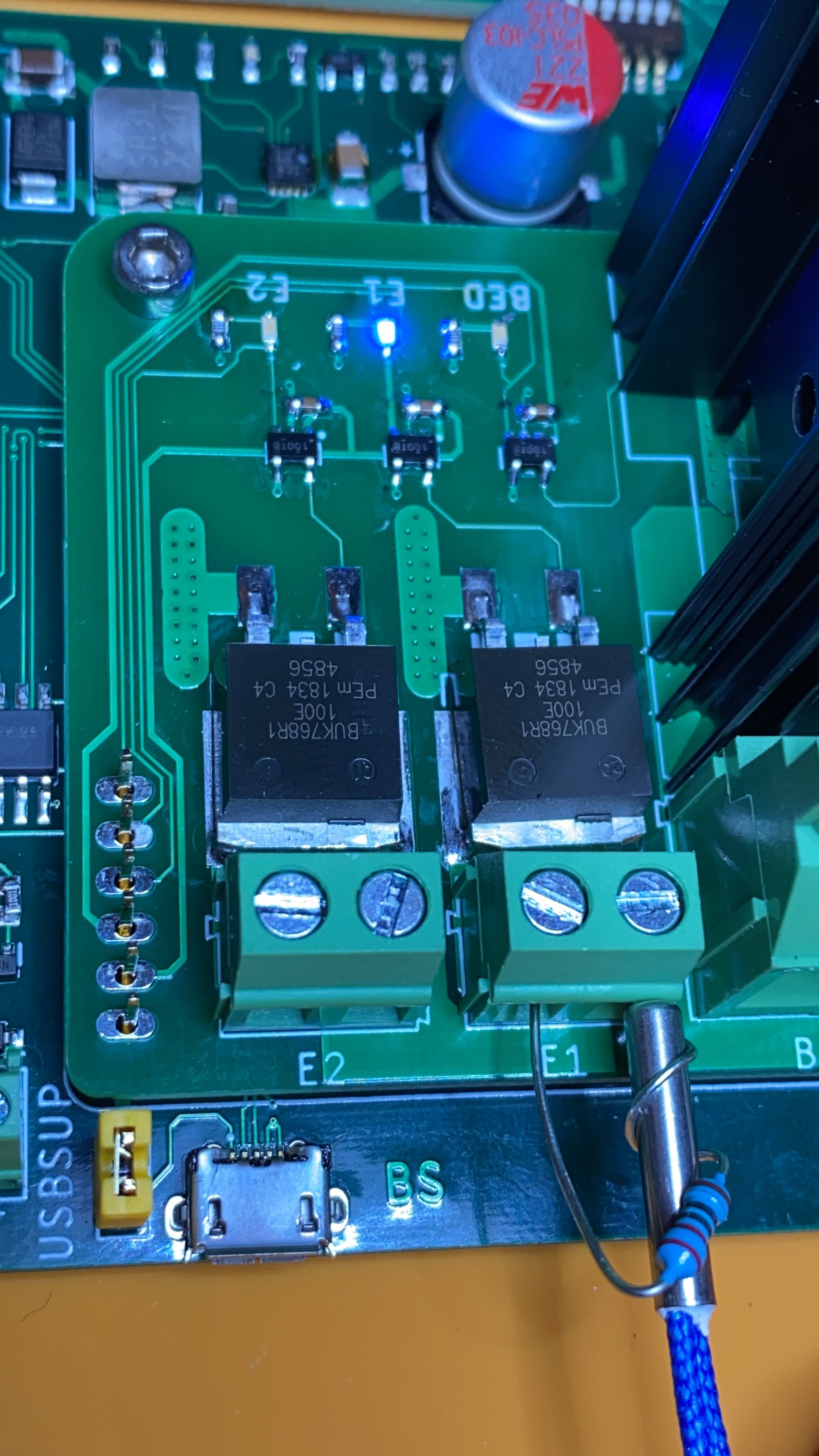
I was very proud of this test, using a 1/4W 220 Ohms resistor wrapped around an e3d thermistor to check the functionality of the heater channels. Worked up to 70°C
So here we are, after several nights of soldering and testing.
Connecting the dots
To put everything to work I decided to rewire the heavily modified Tronxy X5 that was sitting around in my office. Originally (well sort of) this one was equipped with an old MKS SBase and a Raspberry Pi 2 running Klipper.
Went ahead and order a crimping tool & cable ducts and went back to work. Didn´t took any "before" photos as it was a really ugly thing an nothing I´d wanted to show. But at least there is an after
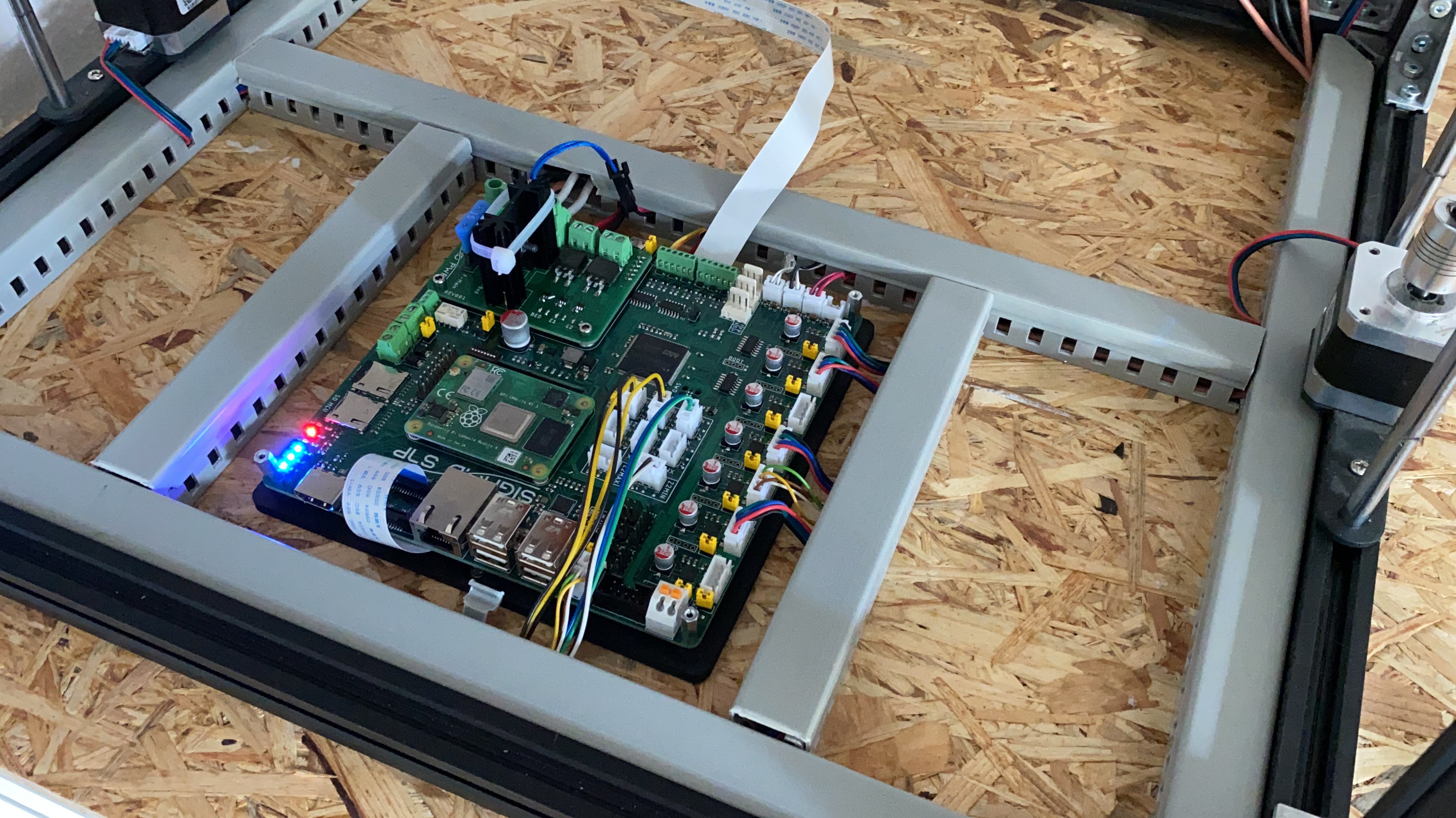
I´m still missing a few things here, I definitely want to have back my touchscreen for manual control but need to order a few fitting cables to get everything nice and tidy. I also ran out of zipties, don´t ask me how...
At the moment I´m monitoring the temperature of the heatsink for the bed heater mosfet with another thermistor. Just to make sure I don´t end up with a lot of magic smoke.
What´s next
As you can see in the pictures there are still many connectors unused, especially CAN is something I absolutely want to try and see in action here. I´ll also have to add my dedicated emergency-stop switch somewhere around the printer.
I also got the impression that there might be people out there who want one of those boards if it happens to come available commercially so I´m looking into this as well. If you have feedback on this topic please leave me a comment. I also have enough ideas for the future to build a whole product line of 3D printer boards with other properties but we´ll see if I ever get to make them.
Possible future ideas would be modular power circuitry to support multi-extruder setups or a board with stepsticks instead of integrated drivers.
Footnote: if you want the most recent updates on this, make sure to follow me on instagram