 Simon Merrett
Wouldn't it be cool to sync a project to the rotation of our planet with respect to its star? Of course! But it turns out it could also be useful, from a timekeeping perspective in cheap, low power electronic systems.
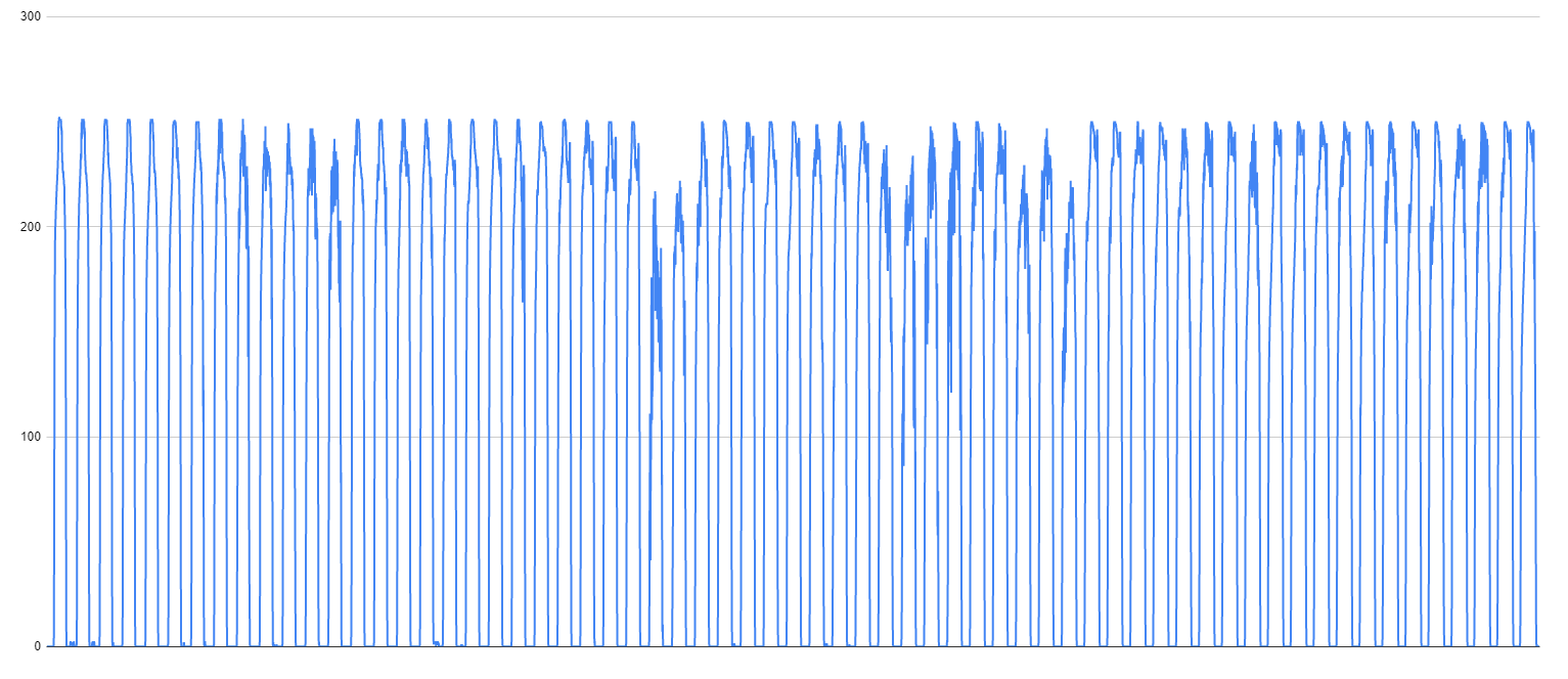
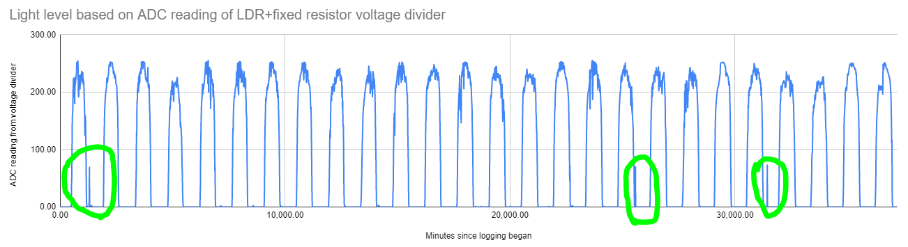
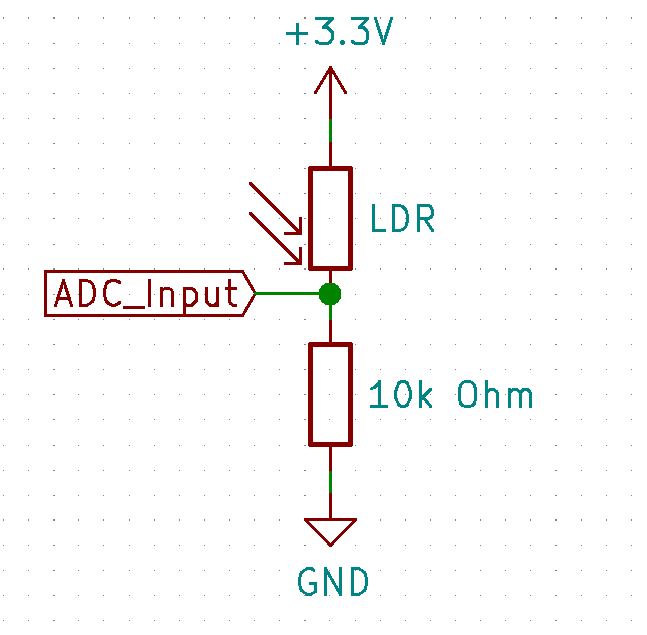
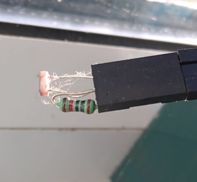
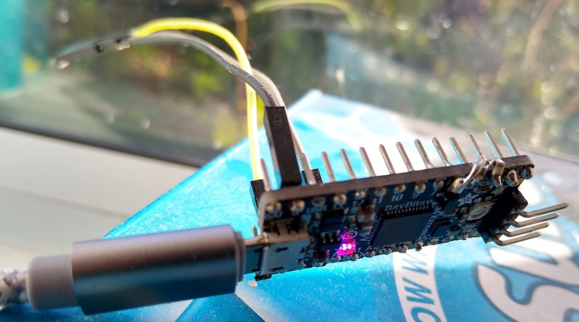
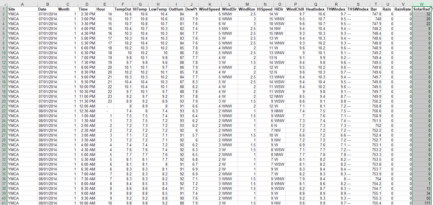
The devices I was using had the option of running a separate real time clock (RTC) on them, and they also had a light dependent resistor (LDR) voltage divider attached to the analogue to digital converter ADC. Although the RTC was accurate (DS3231) and attractive, the inability to easily let a user who was changing the batteries set the time (and a battery backup wasn't an option I entertained for long) meant I was very keen to explore rough time sync with the LDR. It was also much cheaper, on a tight BOM cost.
Thus began my search for a way to keep my microcontrollers from drifting off after days, weeks or months deployed, using daylight as the synchronising signal.
This project is a summary of my progress so far, links to useful resources and an introduction to some of the challenges, concepts and terms encountered along the way.
 Hugh Brown (Saint Aardvark the Carpeted)
 Joel Murphy
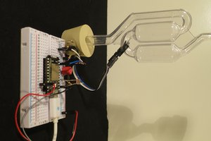
 Alex
Alex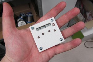
 jaromir.sukuba