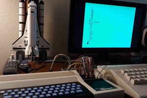
Close
0%
0%

PDP-8 FPGA

Building a PDP-8 on an FPGA

Similar projects worth following
Starting from
$12.00
land_boards has 826 orders / 20reviews
Ships from United States of America
This project starts from Tom Almy's PDP-8 Class Project book (link below) and makes it work on an inexpensive Altera FPGA card. Tom's design includes the VHDL FPGA code and a PDP-8 Assembler.

4K (12-bits) words of Internal SRAM are the PDP-8 system memory. The code gets loaded at boot time into the SRAM.

The FPGA Base card is a Land Boards RETRO-EP4CE15 card and uses a QMTECH Cyclone IV EP4CE15 FPGA card. The RETRO-EP4CE15 card is based on the Multicomp design by Grant Searle. This build has also been done on a EP2C5 FPGA card.

First cut of the design was to make a front panel-less version. Challenges involve loading the program without a Front Panel. Used the loadable SRAM to get this working. Needed to write a Python tool to convert the binary file to the Memory Initialization File (MIF file).

Designed a front panel and got it working.

Demo Video

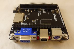
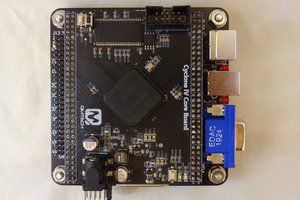
Base card is a Land Boards RETRO-EP4CE15 card. FPGA card is a QMTECH Cyclone IV EP4CE15 card. Design is based on Tom Almy's book The PDP-8 Class Project: Resoling An Old Machine.

Features Set

  • Altera EP4CE15 FPGA card
    • Also, Altera EP2C5 FPGA card
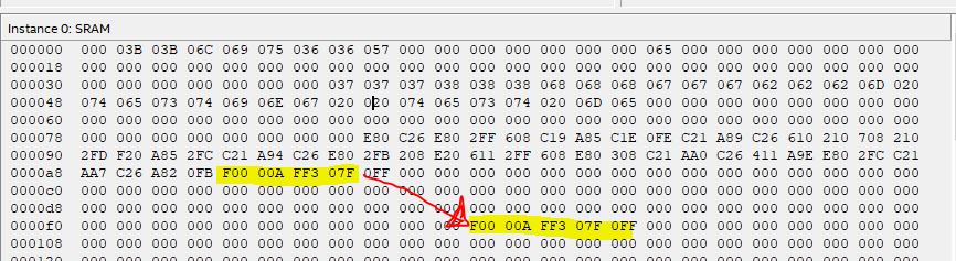
  • 4K of 12-bit words SRAM memory in the FPGA
    • Loadable at power on
  • UART with USB Serial for terminal interface
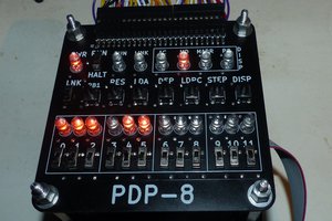
  • Custom Front Panel PCB based on the PDP-8/F front panel

Source Assembler

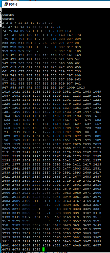
Tom has a website listed at the end of his book. Tom's website includes the C source code for a PDP-8 assembler as well as some example code. 

The PDP-8 assembler does not compile under Windows with Visual Studio but it does compile under Linux. I'm running GCC under VirtualBox with Linux Mint

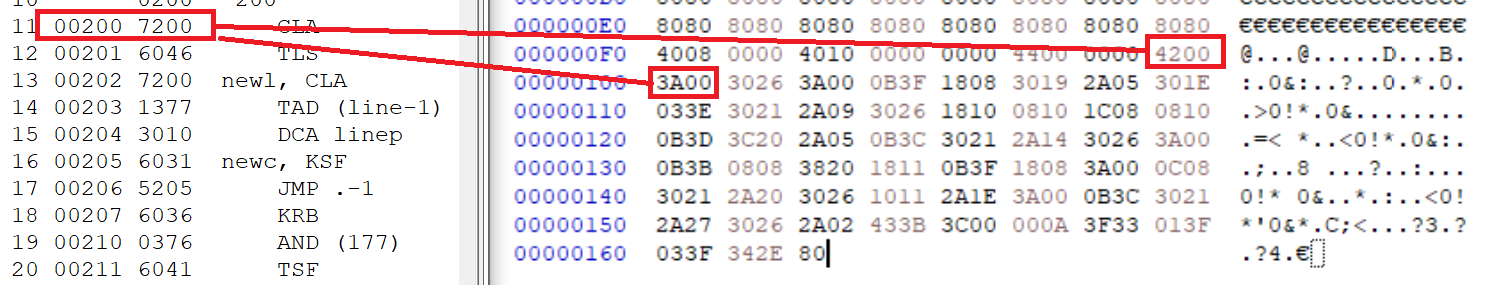
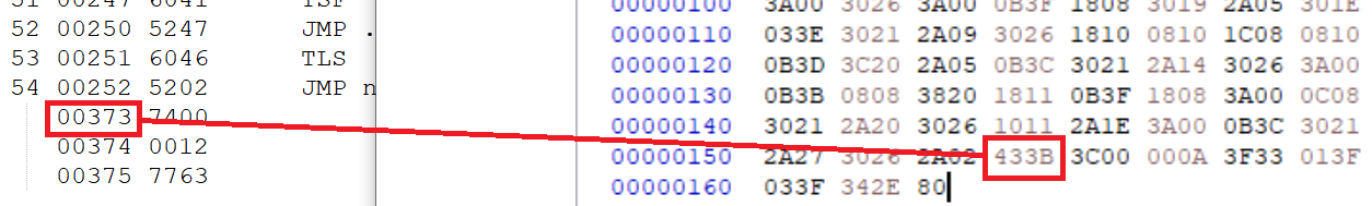
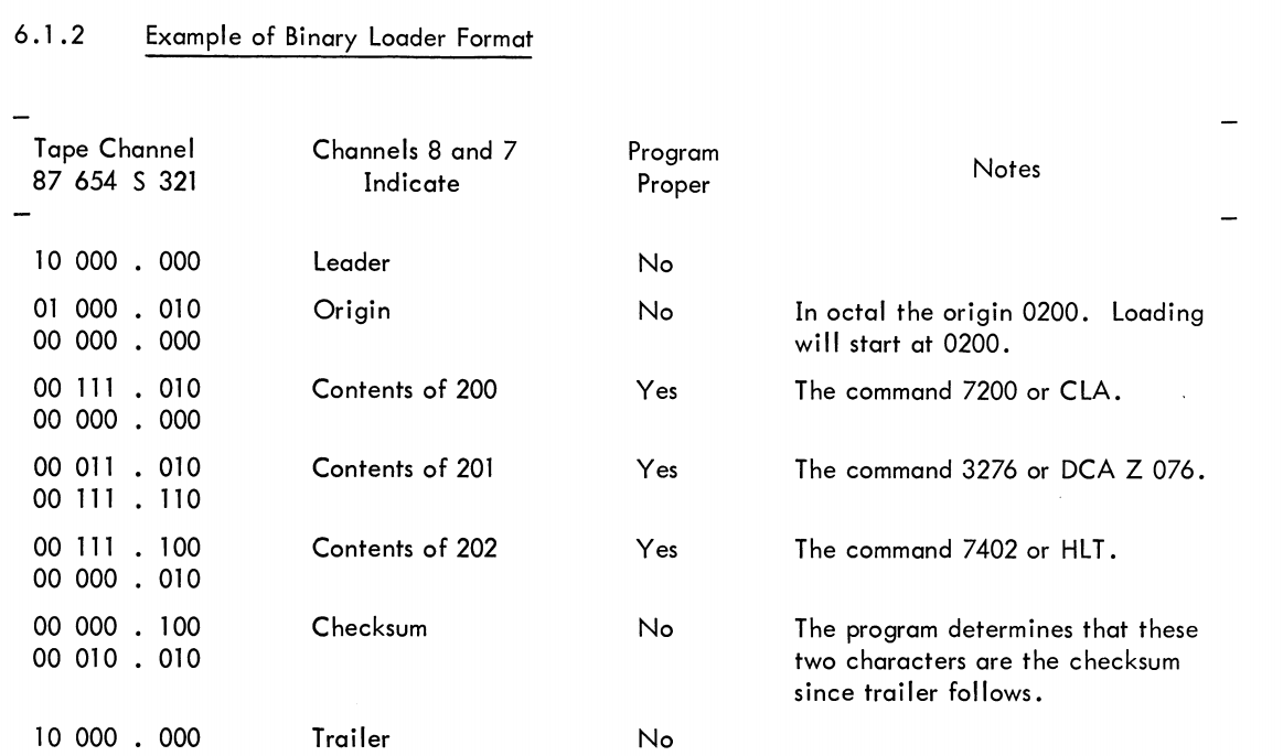
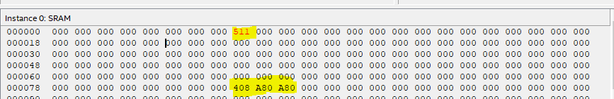
DEC Bin to MIF file Converter

A major contribution was to write a DEC Bin file to MIF file converter. This allows the program to be stored in the FPGA and loaded when the FPGA is started up. The program is assumed to always start at address 200 (oct).
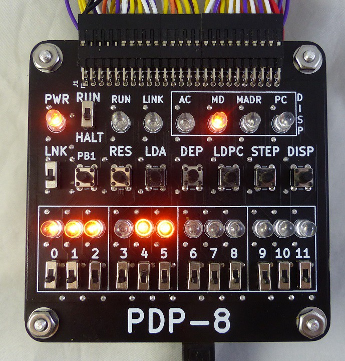
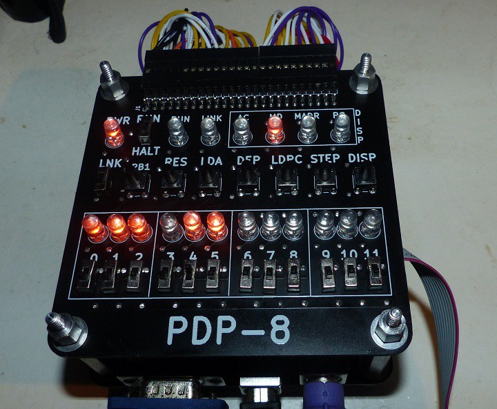
Front Panel

I've designed a Front Panel modelled on the PDP-8/F. I used orange LEDs to match the PDP-8/E colors (Wikipedia picture). The panel has a button which selects what is shown on the LEDs. The Front Panel design is 95x95mm and is designed to fit in a stack-up above the RETRO-EP4CE15 card.

The Front Panel card has a 2x25 pin connector which wires to the RETRO-EP4CE15 I/O connector. The card does not use 9 of the 50 pins so these can be used by the FPGA card design for other functions. The Front Panel card provides extra 3.3V Power/ground connections for other peripheral cards. 

Front Panel Features

  • 12 slide switches for entering PC, Memory Address, Memory Data, and Accumulator values
  • 12 Orange or Red LEDs
  • Bits count up from left to right
  • Display Select pushbutton cycles between PC, Memory Address, Memory Data, and Accumulator
  • (4) LEDs display which function is displayed on the 12 LEDs
  • STEP - Single Step
  • LDPC - Load Program Counter
  • DEP - Deposit data to memory
  • LDA - Write the Accumulator
  • RES - Reset the CPU
  • PB1 - Spare Pushbutton
  • LNK - Slide switch to set the Link Bit
  • LINK LED - Display the Link Bit value
  • RUN - Run LED
  • RUN/HALT - Slide switch for run or halt
  • Power LED

Real PDP-8/e Front Panel

For reference.

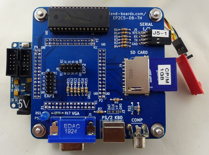
RETRO-EP4E15 Base Card

The base card provides quite a few functions which could be used in an expanded design.

  • USB-Serial - used as the TTY Serial Connection - USB B connector powers the card
  • SD Card
  • VGA (2:2:2 R:G;B)
  • PS/2 Keyboard
  • Additional 2x6 right angle header with grounds for configuration jumpers (requires pullups in the FPGA)
  • J1 - 2x25 I/O connector maps directly to Front Panel connections (with pins left over for other external functions)

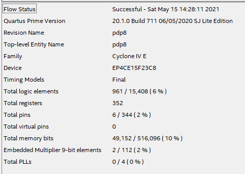
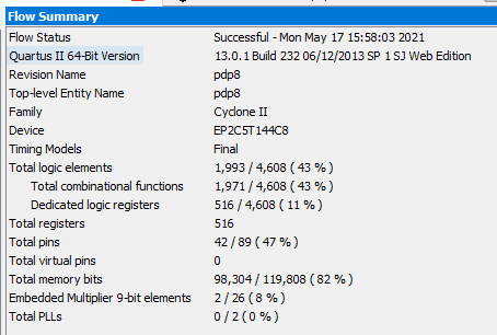
FPGA Resources (in Cyclone IV EP4CE15)
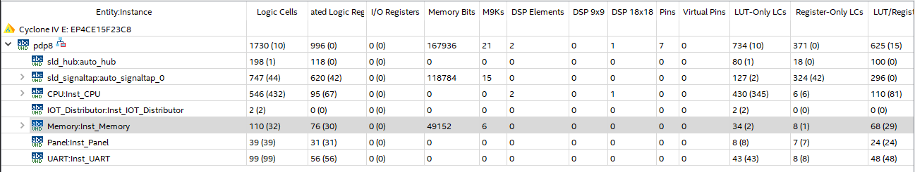
  • Touched up bin2mif.py

    land-boards.com05/27/2021 at 10:21 0 comments

    I touched up the binary to MIF utility (bin2mif.py) to set the address to octal. That makes it easier to map to the PAL list file. The top of the MIF file now looks like:

    -- File: sievePlusLoaders.mif
    -- Generated by bin2mif.py
    -- 
    DEPTH = 4096;
    WIDTH = 12;
    ADDRESS_RADIX = OCTAL;
    DATA_RADIX = OCTAL;
    CONTENT BEGIN
    0000: 0000 0000 0000 0000 0000 0000 0000 0000;
    0010: 0000 0000 0000 0000 0000 0000 0000 0000;
    0020: 0000 0000 0000 0000 0000 0000 0000 0000;
    0030: 0000 0000 0000 0000 0000 0000 0000 0000;
    0040: 0000 0000 0000 0000 0000 0000 0000 0000;
    0050: 0000 0000 0000 0000 0000 0000 0000 0000;
    0060: 0000 0000 0000 0000 0000 0000 0000 0000;
    0070: 0000 0000 0000 0000 0000 0000 0000 0000;
    0100: 0000 0000 0000 0000 0000 0000 0000 0000;
    0110: 0000 0000 0000 0000 0000 0000 0000 0000;
    0120: 0000 0000 0000 0000 0000 0000 0000 0000;
    0130: 0000 0000 0000 0000 0000 0000 0000 0000;
    0140: 0000 0000 0000 0000 0000 0000 0000 0000;
    0150: 0000 0000 0000 0000 0000 0000 0000 0000;
    0160: 0000 0000 0000 0000 0000 0000 0000 0000;
    0170: 0000 0000 0000 0000 0000 0000 0000 0000;
    0200: 7300 6046 7200 1377 3010 1376 3022 3410;
    0210: 2022 5207 7305 3020 7200 1020 4775 1423;
    0220: 0024 7440 5247 7200 1020 3021 7300 1021;
    0230: 1020 7430 5247 3021 1021 4775 1024 7040;
    

     This correlates to the lst file:

       13             
       14       0010  *10
       15 00010 0000  incval, 0       / For autoincrementing
       16       0020  *20             / Our variables
       17 00020 0000  checking, 0
       18 00021 0000  multiple, 0
       19 00022 0000  ii, 0
       20 00023 0000  ptr, 0          / Calculated memory location and mask
       21 00024 0000  memmask, 0
       22       5000  *5000
       23 05000 0000  sieve, 0        / Sieve is 512 words, so location 5000 to 5777
       24             
       25       0200  *200            / start of program
       26 00200 7300  main,   CLA CLL
       27 00201 6046          TLS     / Reset the TTY
       28             
       29             / Clear the array
       30 00202 7200          CLA
       31 00203 1377          TAD     (sieve-1)       / put address of array-1 in incval
       32 00204 3010          DCA     incval
       33 00205 1376          TAD     (-words)        / Put -size of array in i
       34 00206 3022          DCA     ii
       35 00207 3410  loop1,  DCA     I incval        / Store 0 in successive locations
       36 00210 2022          ISZ     ii              / until end of array
       37 00211 5207          JMP     loop1
       38             
       39             / Do the marking
       40 00212 7305          CLA CLL IAC RAL         / 2
       41 00213 3020          DCA     checking        / initialize checking variable
       42 00214 7200  loop2,  CLA
       43 00215 1020          TAD     checking        / get checking variable
       44 00216 4775@         JMS     calcpm
       45 00217 1423          TAD     I ptr           / get memory word
       46 00220 0024          AND     memmask         / get the bit
     

     Now I'm trying to get the bin loader working over the serial port. Not sure what the serial protocol is. Must 8 bits of data, though.

  • Demonstration Video

    land-boards.com05/23/2021 at 15:37 0 comments

    Put together a short highlights video.

  • Front Panel Operation

    land-boards.com05/22/2021 at 12:58 0 comments

    PCB arrived. Built it. Tested it. It took a lot of FPGA tweeks to get it working like I want.

    Pushbuttons

    • DISP - cycles  between DISP LEDs [AC, MD, MADR, PC]
    • STEP - single step the CPU
    • LDPC - load the PC from the bottom slide switches
    • DEP - store the value from the bottom slide switches to the memory at the current Program Counter
    • LDA - load the Accumulator  from the bottom slide switches
    • RES - reset the CPU
    • PB1 - spare

    Slide Switches

    • 0-11  value that is loaded by the pushbuttons. Also the address value in MD mode
    • LNK - set the LINK bit when the accumulator is loaded (not yet  implemented?)
    • RUN/HALT - up = Run the CPU from the current PC, down = Halt the CPU

    LEDs

    • 0-11 - displays the value in the register/memory location selected by the DISP LEDs and selected by the DISP pushbutton
    • PC - display the Program Counter value on 0-11 LEDs 
    • MADR - Not used
    • MD - displays the data in memory at the current PC on 0-11 LEDs
    • AC - displays the Accumulator value on 0-11 LEDs
    • LINK - display the link bit (not yet implemented?)
    • RUN - illuminated when the CPU is running, off when the CPU is halted
    • PWR - power LED

    Mounted above FPGA Card

  • Ported to EP2C5 (Multicomp) FPGA

    land-boards.com05/17/2021 at 20:28 0 comments

    Ported the design to the original Multicomp FPGA. Works great. 

    Webpage for FPGA adapter card.

    Fills up the Internal SRAM resources. Room for more logic left over.

  • Interpreting DEC BIN Files

    land-boards.com05/16/2021 at 11:27 1 comment

    Data Section

    Here's a look at the echo list file vs hex dump of the binary file for the data section.

    The header is demarked as values of 0x80.

    Addresses are marked as values of 0x40-0x4F. The data value follows. This is shown to be more complicated in the above example where the last item data is placed at 400 which is after the code. To fix this, bin2mif would need to keep track of this and do the writes.

    The weird part is the address encoding. For the first locations, the address in the listing is in octal and the address in the hex window is in hex. That makes sense. However, for the final value the number is 400 in both windows - strange? Not really since the upper 2 bits of the second byte get discarded.

    Code Section

    Now, take a look at the code section. The mapping is the same here:

    The first cut at the bin2mif program read in the binary data until it found the 4200 (oct) and snagged the following data. That worked fine for the contiguous section of code, but didn't work for section after the code which had to be manually copied in the In System Memory Editor:

    It would be nice if the bin2mif utility could handle this. This transition is also marked in the same way:

    Fixing bin2mif, then, involves detecting the same address bit and filling out the gap between the end of the previous data and the start of the next data section.

    Another way would be to have a 4K Word array and fill it as data arrives. That's arguably the best way to handle this.

    Re-Wrote bin2mif.py

    Re-factored the bin2mif code to interpret the addresses. It worked with the echo code. Command line was:

    python ..\bin2mif_2.py echo.bin > echo.mif

    Tested with the sieve code and it worked:

    Success!

  • Running echo.pal example

    land-boards.com05/15/2021 at 18:07 0 comments

    The echo.pal example program reads characters from the serial port and echos them out as they are entered. When Enter is pressed, the entire line gets sent to the serial port.

    In the previous log I created a utility bin2mif that does a simple translation of the DEC bin file into a memory initialization file. The program only copies code sections and doesn't deal with non-contiguous code sections. This limitation is fine for the data since it should all be set to zero anyway but it's a problem for the non-contiguous code sections in echo.pal.

    Here's the echo.lst file:

        1             / Serial port test (echo)
        2             / http://homepage.divms.uiowa.edu/~jones/pdp8/man/tty.html
        3       0010  *10
        4 00010 0000  linep, 0
        5       0020  *20
        6 00020 0000  saved, 0
        7 00021 0000  count, 0
        8       0400  *400             / Line stored here
        9 00400 0000  line, 0
       10       0200  *200
       11 00200 7200      CLA          / Clear Accumulator
       12 00201 6046      TLS          / Teleprinter Load and start
       13 00202 7200  newl, CLA        / Clear Accumulator
       14 00203 1377      TAD (line-1)
       15 00204 3010      DCA linep
       16 00205 6031  newc, KSF           / Keyboard Skip if Flag (input data is ready)
       17 00206 5205      JMP .-1       / 
       18 00207 6036      KRB          / Keyboard Read and begin next read
       19 00210 0376      AND (177)    / Get rid of parity bit
       20 00211 6041      TSF          / Teleprinter Skip if Flag
       21 00212 5211      JMP .-1
       22 00213 6046      TLS          / Teleprinter Load and start (Echo it)
       23 00214 3020      DCA saved    / save a copy
       24 00215 1020      TAD saved
       25 00216 3410      DCA I linep  / store it away
       26 00217 1020      TAD saved
       27 00220 1375      TAD (-15)    / CR character?
       28 00221 7440      SZA          / finished line if so - Skip next instruction if Zero Accumulator
       29 00222 5205      JMP newc
       30 00223 1374      TAD (12)     / Echo line feed as well
       31 00224 6041      TSF          / Teleprinter Skip if Flag
       32 00225 5224      JMP .-1
       33 00226 6046      TLS          / Teleprinter Load and start (Echo it)
       34             / Now echo the line
       35 00227 7200      CLA          / Clear Accumulator
       36 00230 1373      TAD (-line)
       37 00231 1010      TAD linep    / get number of characters
       38 00232 7040      CMA          / minus the number
       39 00233 3021      DCA count
       40 00234 1377      TAD (line-1) / reset starting address
       41 00235 3010      DCA linep
       42 00236 7200  echoc, CLA       / Clear Accumulator
       43 00237 1410      TAD I linep  / get character
       44 00240 6041      TSF          / Teleprinter Skip if Flag
       45 00241 5240      JMP .-1
       46 00242 6046      TLS          / Teleprinter Load and start
       47 00243 2021      ISZ count    / Increment and store
       48 00244 5236      JMP echoc
       49 00245 7200      CLA          / Clear Accumulator
       50 00246 1374      TAD (12)
       51 00247 6041      TSF          / Teleprinter Skip if Flag
       52 00250 5247      JMP .-1
       53 00251 6046      TLS          / Teleprinter Load and start
       54 00252 5202      JMP newl
          00373 7400
          00374 0012
          00375 7763

    The problem here is the values in locations 373-375 (oct). They get placed immediately after the code at 263-255, These can be manually inserted using the In System Memory editor.

    The Quartus In System Memory Editor can be used to do an export of the data (first select all). Saved the code as echo_fixed.mif.

    The result is that the echo code runs on the PDP-8 FPGA.

  • PDP-8 Software Toolchain

    land-boards.com04/24/2021 at 20:24 0 comments

    Build PDP-8 Assembler Tool

    • Assembler macro8x.c generates binary (DEC bin) files from PDP-8 Assembly Language files
    • Notes from macro8x.c source code
    This program has been built and successfully executed on:   
    Linux (80486 CPU) using gcc   
    RS/6000 (AIX 3.2.5)   
    Borland C++ version 3.1 (large memory model)   
    Borland C++ version 4.52 (large memory model) with no modifications to the source code.
    On UNIX type systems, store the the program as the pal command and on 
    PC type systems, store it as pal.exe
    
    • Command line to compile assembler (under Linux GCC):
    gcc macro8x.c
    
    • macro8x.c would not compile under VisualStudio
    • macro8x.c source compiled without error under Linux Mint under VirtualBox

    Simple Test Program

    I wrote a very simple test program, easy.pal . The program continually increments a memory location, at 10 (oct).

    • Compile easy.pal code using:
    ../macro8x -x easy.pal
    

    List file is:

    1 0010 *10
    2 00010 0000 linep, 0
    3 0200 *200
    4 00200 2010 ISZ linep
    5 00201 5200 JMP .-1
    6 00202 5200 JMP .-2
    7
    No detected errors

    The binary file from macro8x easy.bin as viewed in HxD (as 16-bit hex values) is:

    Bin to MIF Utility

    The output of the macro8x assembler is DEC bin loader format. The DEC bin format is described in DEC-OO- LBAA-D:

    Wrote a utility, bin2mif.py to convert binary loader data to Altera Memory Initialization (MIF) files. The program:

    • Ignores the (0x80) header values and ignores the data section (0x4008 0x0000 values)
    • Looks for the code section (starting with 0x4200)
    • Assumes code starts at 200 (oct). This could be pulled from the 0x4200 location,
    • Pads the first 200 (oct) locations with 0000 (oct).

    Here's the output:

    -- Generated by bin2mif.py
    --
    DEPTH = 131;
    WIDTH = 12;
    ADDRESS_RADIX = DECIMAL;
    DATA_RADIX = OCTAL;
    CONTENT BEGIN
    0000: 0000 0000 0000 0000 0000 0000 0000 0000;
    0008: 0000 0000 0000 0000 0000 0000 0000 0000;
    0016: 0000 0000 0000 0000 0000 0000 0000 0000;
    0024: 0000 0000 0000 0000 0000 0000 0000 0000;
    0032: 0000 0000 0000 0000 0000 0000 0000 0000;
    0040: 0000 0000 0000 0000 0000 0000 0000 0000;
    0048: 0000 0000 0000 0000 0000 0000 0000 0000;
    0056: 0000 0000 0000 0000 0000 0000 0000 0000;
    0064: 0000 0000 0000 0000 0000 0000 0000 0000;
    0072: 0000 0000 0000 0000 0000 0000 0000 0000;
    0080: 0000 0000 0000 0000 0000 0000 0000 0000;
    0088: 0000 0000 0000 0000 0000 0000 0000 0000;
    0096: 0000 0000 0000 0000 0000 0000 0000 0000;
    0104: 0000 0000 0000 0000 0000 0000 0000 0000;
    0112: 0000 0000 0000 0000 0000 0000 0000 0000;
    0120: 0000 0000 0000 0000 0000 0000 0000 0000;
    0128: 2010 5200 5200;
    END;

    Loaded the easy.mif file. Got the expected warning loading it into Quartus (it's OK).

    Critical Warning (127005): Memory depth (4096) in the design file 
    differs from memory depth (131) in the Memory Initialization File 
    "C:/Users/HPz420/Documents/GitHub/Doug Gilliland/Linux-68k/pdp8/
    PDP8_Programs/easy.mif" -- setting initial value for remaining
    addresses to 0.

    Ran. It worked great. The code is at the correct place and increments the location 10 (oct).

    Code loaded at 200 (oct) which is 0x80 (hex), Verified data changes with In System Memory Content Editor. 

    And again:

    Success!

View all 7 project logs

Enjoy this project?

Share

Discussions

Similar Projects

Does this project spark your interest?

Become a member to follow this project and never miss any updates