 Subhajit
In this IoT project, I have shown how to make an IoT-based Smart Home with Google Assistant & Alexa using NodeMCU ESP8266 to control 3 home appliances with voice commands.
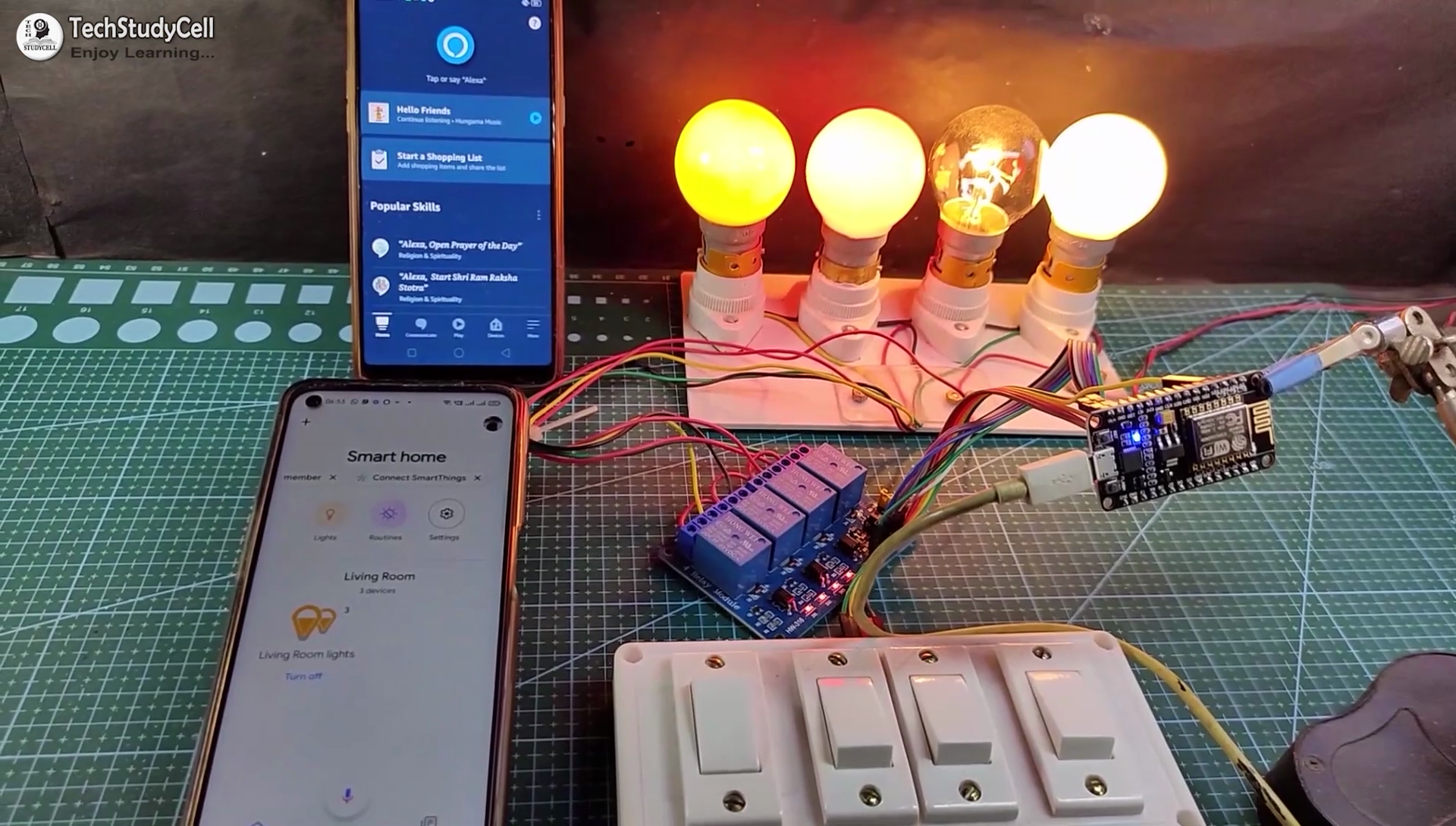
If the internet is not available, then you can control the home appliances from manual switches. During the article, I have shown all the steps to make this smart home system.
This complete Home Automation system has the following features:
- Control appliances with Google Assistant
- Control appliances with Alexa
- Control appliances manually with switches.
- Monitor real-time feedback in the Google Home and Amazon Alexa App.
- Control home appliances manually without internet.
- All resources used for this project are FREE.
So, you can easily make this home automation project at home.
Required Components:

1. NodeMCU board
2. 4-channel SPDT 5V Relay Module
3. Manual Switches or Push Buttons
4. Alexa Echo Dot (Optional)
If you use the custom-designed PCB for this project, then please refer to the following required components list.
Required Components for the PCB:
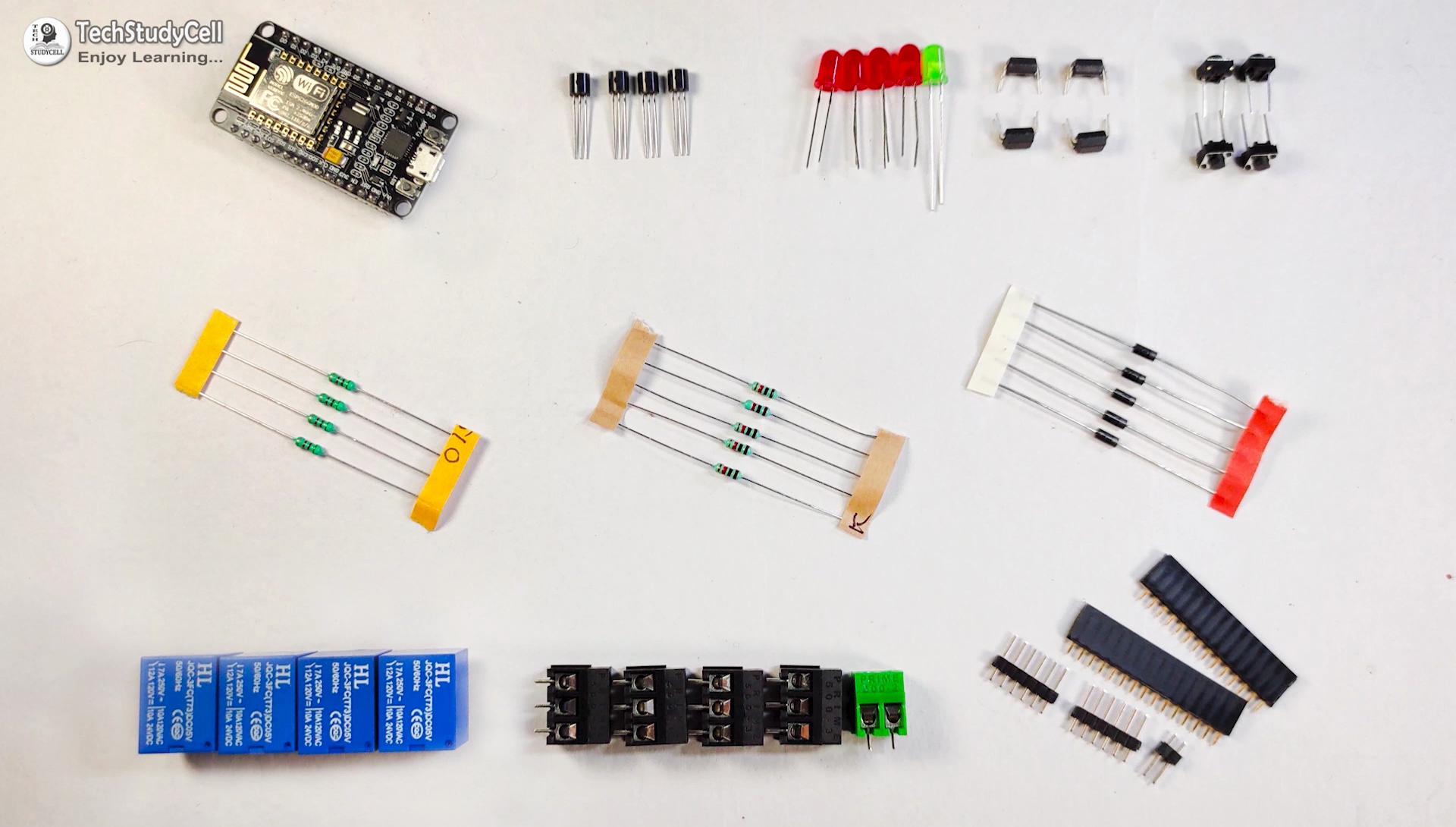
1. Relays 5v (SPDT) (8 no)
2. BC547 Transistors (8 no)
3. PC817 Optocuplors (8 no)
4. 510-ohm 0.25-watt Resistor (8 no) (R1 - R8)
5. 1k 0.25-watt Resistors (10 no) (R9 - R18)
6. LED 5-mm (10 no)
7. 1N4007 Diodes (8 no) (D1 - D8)
8. Push Buttons (8 no)
9. Terminal Connectors
10. 5V DC supply
Required Software:
1. Arduino IDE
2. Google Home App
3. Amazon Alexa App
Circuit Diagram of the NodeMCU Home Automation Project:
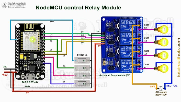
This is the complete circuit diagram for this home automation project. I have explained the circuit in the tutorial video.
The circuit is very simple, I have used the GPIO pins D1, D2, D5 & D6 to control the 4 relays.
And the GPIO pins SD3, D3, D7 & RX connected with switches to control the 4 relays manually.
I have used the INPUT_PULLUP function in Arduino IDE instead of using the pull-up resistors.
I have used a 5V mobile charger to supply the smart relay module.
Here, the D3 pin should not be connected with GND during the booting process of NodeMCU.
Control Relays With Google Assistant Using NodeMCU:

You can also control the home appliances from Amazon Alexa App if the NodeMCU is connected with the WiFi.
You can also ask Alexa to turn on and off the appliances.
You can also control the appliances from the manual switches and monitor the real-time feedback of the relays in the Amazon Alexa App from anywhere in the world.
You don't need any Echo DOT device for this home automation project.
Control Relays Manually With Switches:

If the WiFi is not available, you can control the relays from the manual switches.
The NodeMCU will check for the WiFi after every 5 seconds. When the WiFi is available, the NodeMCU will automatically connect with the WiFi.
Please refer to the circuit diagram to connect the manual switches.
Design the PCB for This Smart Home System:
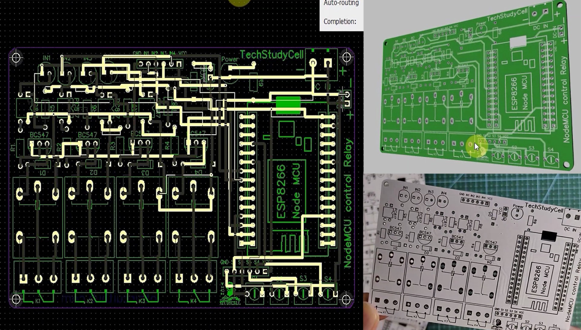
To make the circuit compact and give a professional look, I have designed the PCB after testing all the features of the smart relay module.
You can download the PCB Gerber file of this home automation project from the following link:
https://drive.google.com/uc?export=download&id=1Jx4D_DSV_ei1y0a82AbtxbsNhy8sjCmY
Order the PCB:

After downloading the Garber file you can easily order the PCB
1. Visit https://jlcpcb.com/RHS and Sign in / Sign up
2. Click on the QUOTE NOW button.
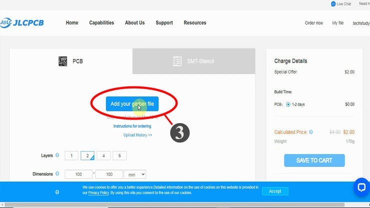
3. Click on the "Add your Gerber file" button. Then browse and select the Gerber file you have downloaded.
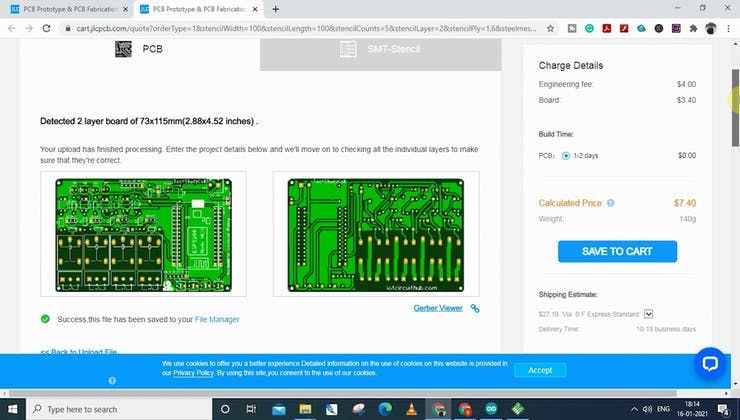
Uploading the Gerber File and Set the Parameters:
4. Set the required parameter like Quantity, PCB masking color, etc.
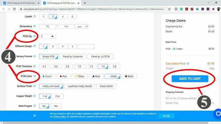
5. After selecting all the Parameters for PCB click on SAVE TO CART button.
Select Shipping Address and Payment Mode:
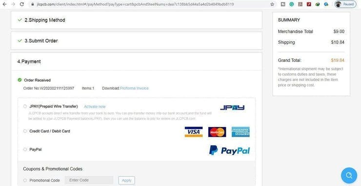
6. Type the Shipping Address.
7. Select the Shipping Method suitable for you.
8. Submit the order and proceed with the payment.
You can also track your order from JLCPCB.com.
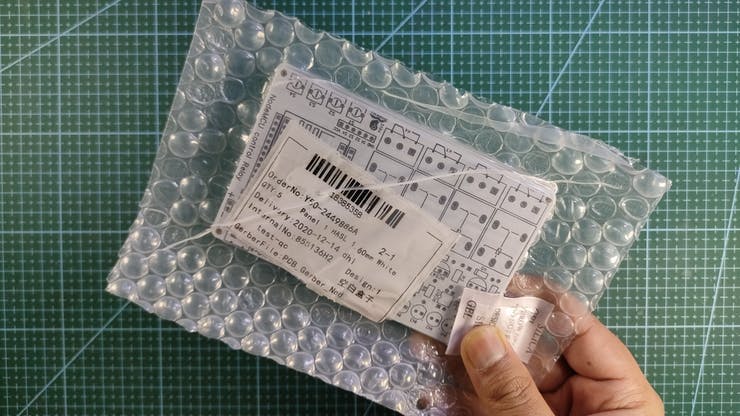
My PCBs took 2 days to get manufactured and arrived within a week using the DHL delivery option.
PCBs were well packed and the quality was really good at this affordable price.
Solder All the Components on PCB:

After that, I have soldered all the components as per the circuit diagram.
Then connect the NodeMCU board with the PCB.
Create an Account in Sinric Pro:

First, visit https://sinric.pro/
You have to create an account in Snric Pro.
Then log in to Sinric Pro Account.

You will get an APP KEY and APP SECRET for the account, which will be required in the code.
Add Room in Sinric Pro account:

After that add a room and give a nickname to that room (Ex: Living Room)
Add Devices in Sinric Pro account:

Then Add devices one by one and give the nickname for each device. Sinric will assign a unique device ID for each device.
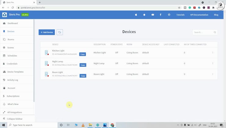
Here, I have used the free Sinric Pro account, so I can add a maximum of 3 devices for free.
Program NodeMCU Using Arduino IDE:

First, download the code & install all the required libraries mention in the code.
Required Libraries:
- Sinric Pro
- ArduinoJson
- WebSockets

Then enter the WiFi credentials
#define WIFI_SSID "YOUR-WIFI-NAME"
#define WIFI_PASS "YOUR-WIFI-PASSWORD"
Enter the APP KEY and APP SECRET from the Sinric pro account Credential menu.
#define APP_KEY "YOUR-APP-KEY"
#define APP_SECRET "YOUR-APP-SECRET"
Enter the Device IDs from the Sinric pro account Devices menu.
#define device_ID_1 "SWITCH_ID_NO_1_HERE"
#define device_ID_2 "SWITCH_ID_NO_2_HERE"
#define device_ID_3 "SWITCH_ID_NO_3_HERE"
#define device_ID_4 "SWITCH_ID_NO_4_HERE"
After that select the NodeMCU 1.0 (ESP-12E Module) board and the PORT. Then click on the upload button.
Setup the Google Home App:
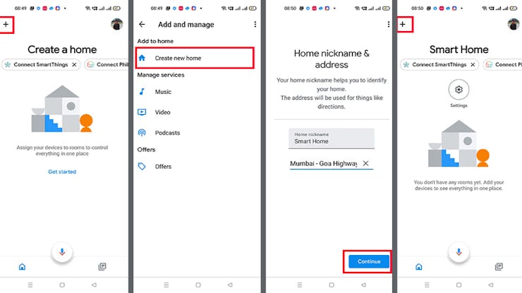
First, download and install the Google Home App. then follow the steps to create Home in Google Home app
- Tap on the "+" icon (upper left corner).
- Tap on Create new home.
- Enter the Home nickname and address.
- Then click on Continue.
The Home is created. Now again tap on the "+" icon to add devices.
Connect Sinric Pro With Google Home App | Add Devices:

After creating the Home in the Google Home app, you can connect the Sinric Pro with the Google Home app
- Tap on the "+" icon, then select Set up device.
- Tap on Works with Google.
- Search for Sinric Pro, then select on Sinric Pro.
- Enter the email id and password used for the Sinric account,
- Then tap on Sign in.
Thus, all the devices from Sinric Pro will be added to Google Home Account.
Configure the Alexa App for This Smart Home System:
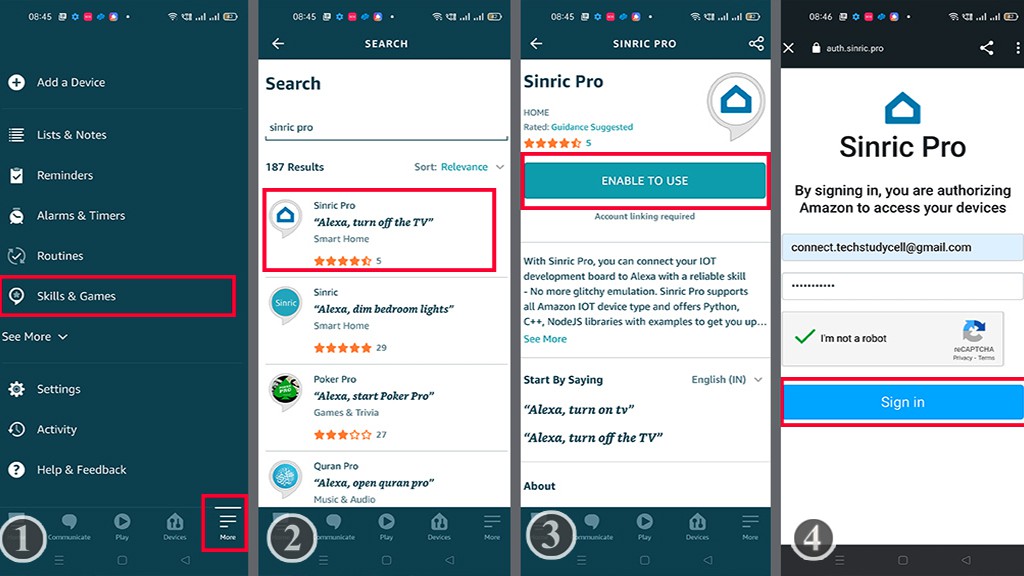
Download and install the Amazon Alexa App from the Google play store or App Store.
- Go to "More", then select "Skills & Games"
- Search for Sinric Pro and tap on "Sinric Pro".
- Tap on "ENABLE TO USE"
- Log in with the Sinric account credentials.
Connecting Devices With Alexa:
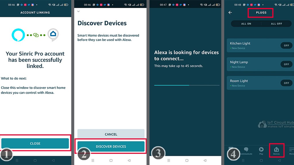
- Tap on CLOSE.
- Tap on "DISCOVER DEVICES".
- It will take a minute to add devices. During this time the NodeMCU should be connected with the WiFi.
- Tap on "Devices", and tap on "Plug" to see all the devices.
Thus, all the devices from Sinric Pro will be added to Amazon Alexa App.
Connect the Home Appliances:

Connect the 4 home appliances with the relay module as per the circuit
Connect the 4 home appliances with the relay module as per the circuit diagram. Please take proper safety precautions while working with high voltage.
Connect 5-volt DC supply with the PCB. (I have used my old mobile charger 5V 5 Amp)
Turn ON the Supply:

Turn on the 110V/230V supply and 5V DC supply.
Finally!! the Smart Home System Is Ready:

I hope you have liked this Google and Alexa control home automation project. I have shared all the required information for this project.
I will really appreciate it if you share your valuable feedback. Also if you have any query please write in the comment section.
Thank you & Happy Learning.