 Dilshan Jayakody
All the parameters of this clock can configure using its USB base serial terminal. The firmware of this clock supports both static and DHCP addressing modes. Apart from that, parameters such as NTP server address, time-offset, and clock display formats can change through the menu-driven configuration terminal.
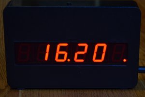
This clock is designed to drive large common-anode, 7-segment displays. The prototype version is assembled using four individual segments of 7.2V, 2.3-inch, red color displays (FJS23101BH). To archive, the necessary high output voltage and the current, the 7-segment display output stage of this clock is formed using ULN2803 Darlington transistor array and BC858 transistors.
The network component of this clock is built around the ENC28J60 10BASE-T stand-alone Ethernet controller.
Highly accurate DS3231M RTC is using in this clock for time-keeping operations. To backup the date and time, the CR1220 type button cell is included in the PCB. The date and time are syncs with the NTP server during the system startup. Users can manually initiate synchronization by pressing the "SYNC" button in the system.
Depending on the NTP server, the user needs to specify the time offset to the system to get the correct local time. Time offset can configure using the system configuration menu, and it must be input in a standard format like +5:30.
Firmware of this clock is developed using the Arduino framework and libraries.
PCBWay provides sponsorship for this project. The PCBWay online ordering service provides excellent help to fabricate this PCB. We got finished PCBs within three days, and the quality of the service is at a superior level. PCB of this project can directly order from PCBWay through this link.
This project is an open hardware project. All the project source codes, schematic diagrams, documentation, PCB designs, and compiled firmware files are available in the project GitHub repository.
 Gigawatts
 Supercrab
 Tamarisk Labs