 stefan.schnitzer
For safety reasons, I wanted to be able to switch the water supply of my home on and off. But I live in a rented place where it is not allowed to modify the main water supply pipes and valves. Thus I tried to build a retrofit ball valve driver with some smart features with has no need for such forbidden modifications.
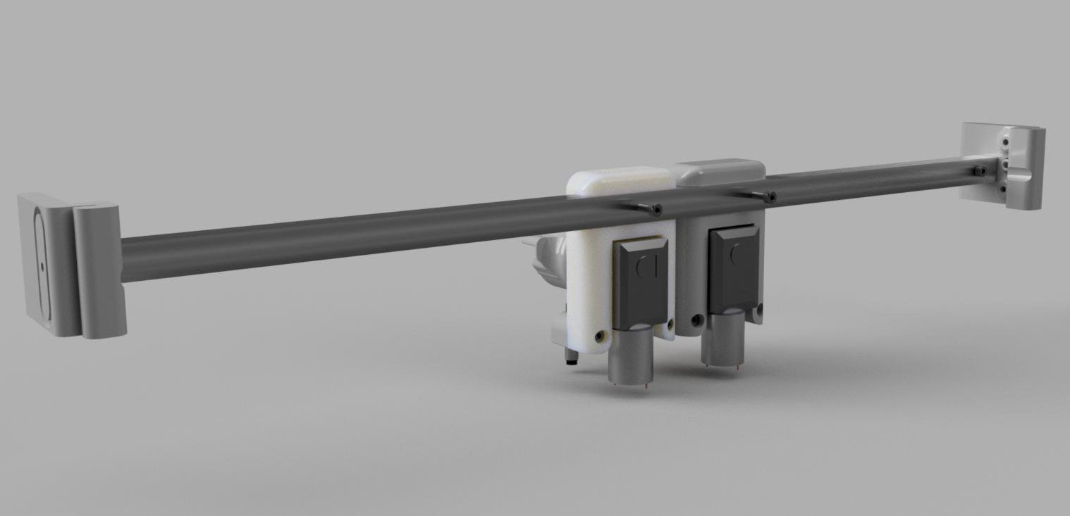
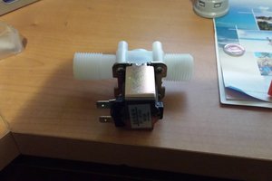
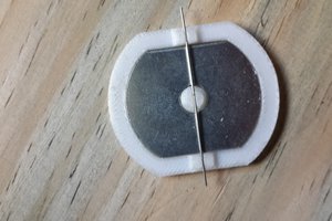
First I needed to solve the mechanical part of the project. The solution was a 3D-printed coupler that goes directly on the normal valve handles. The two ball valves are driven with cheap gear motors and the open/close positions are monitored with inductive (the handles are made out of cast iron) proximity sensors.
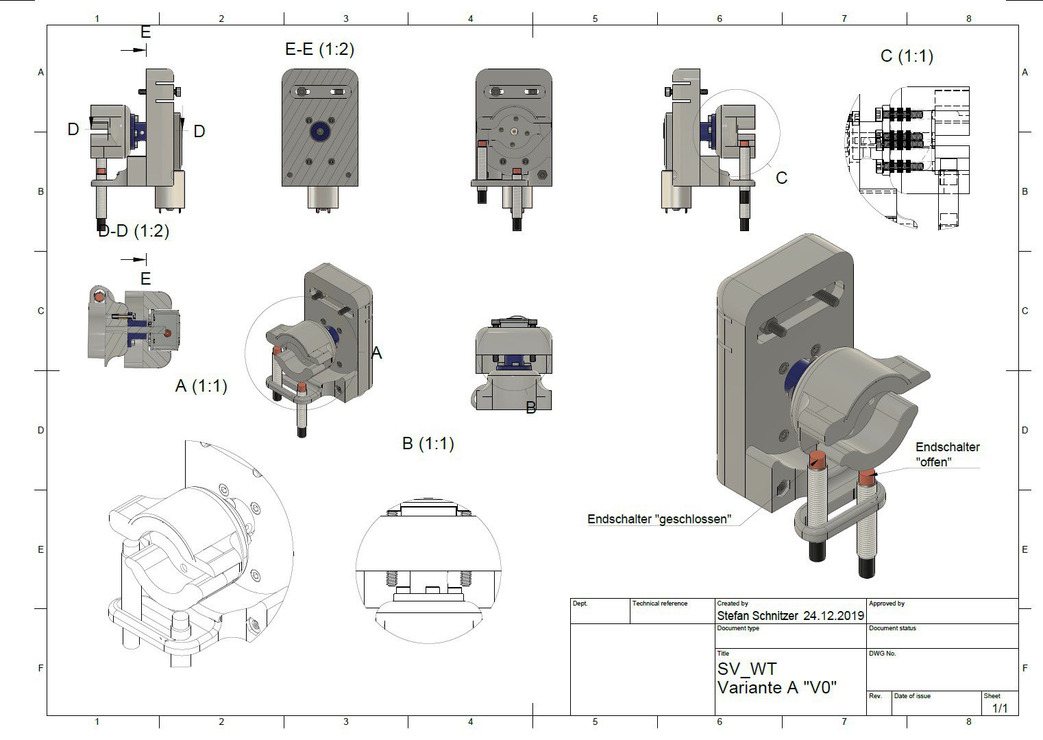
To mount two (one for cold and one for hot water) of these contraptions more printed parts and some aluminium was used.
This simple assembly allowed me to mount (without drilling holes) all components in the water supply box. Additional to the valve drivers three DS18B20 temperature sensors are mounted (with electrical tape and magnets).
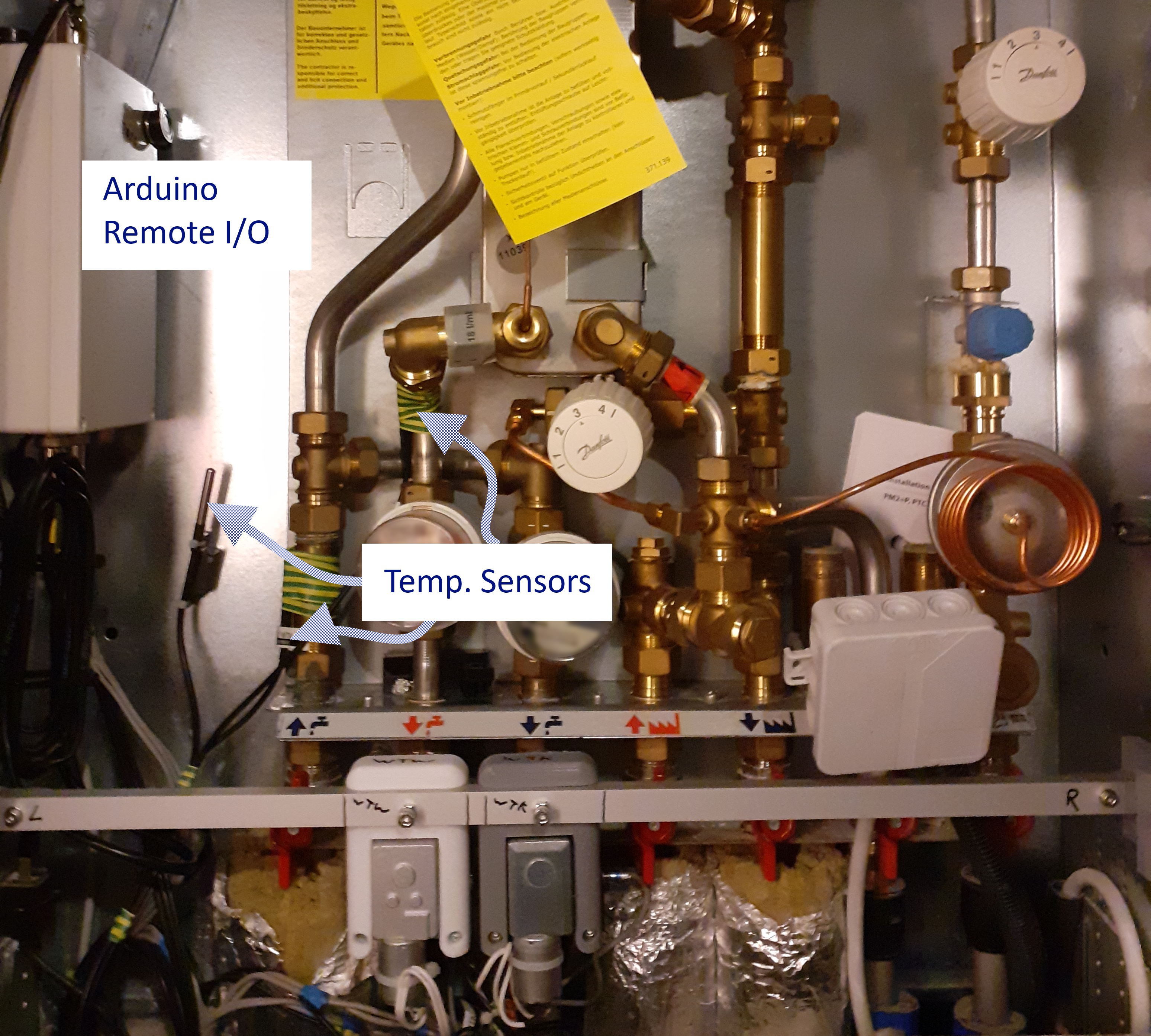
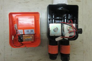
The controller is design similar to my other Arduino Remote I/Os (https://hackaday.io/project/167904-diy-scada-wireless-and-wired-remote-io). This time I tried to make it kinda waterproof and easy to maintain.
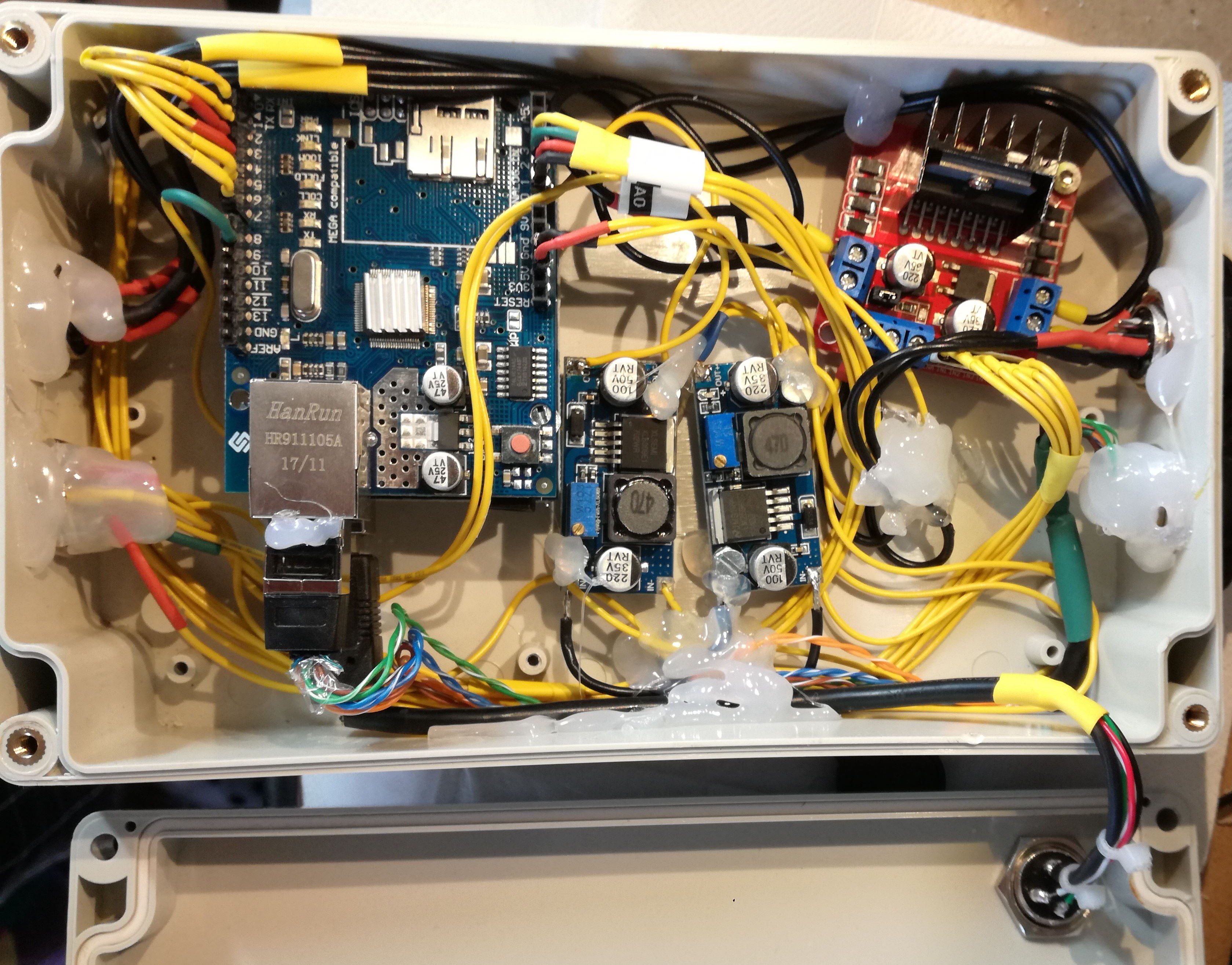
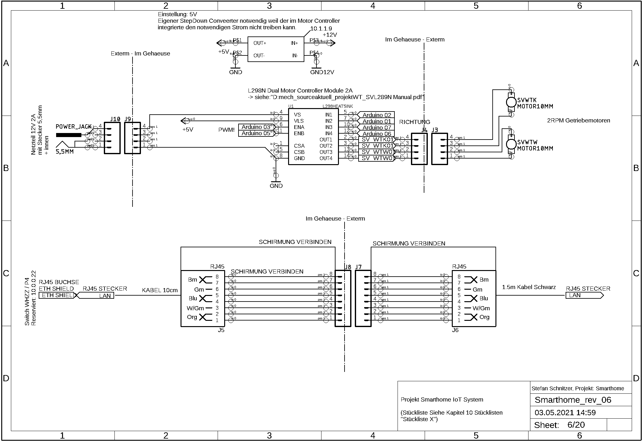
The Box contains an Arduino, a simple H-Bride Motor Controller and two buck converters.
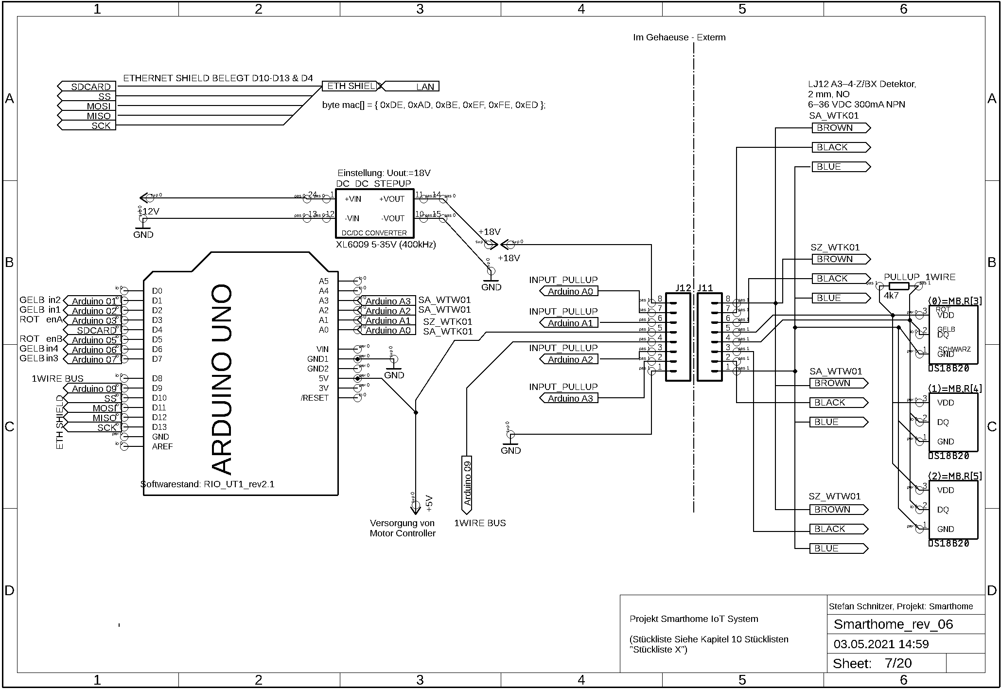
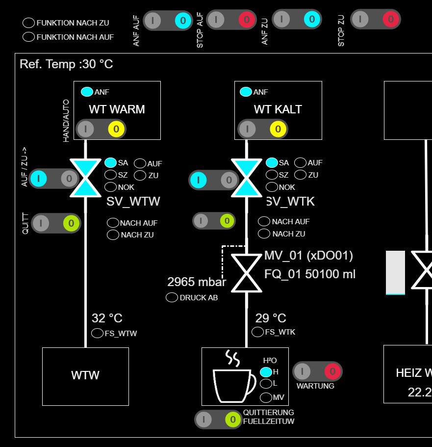
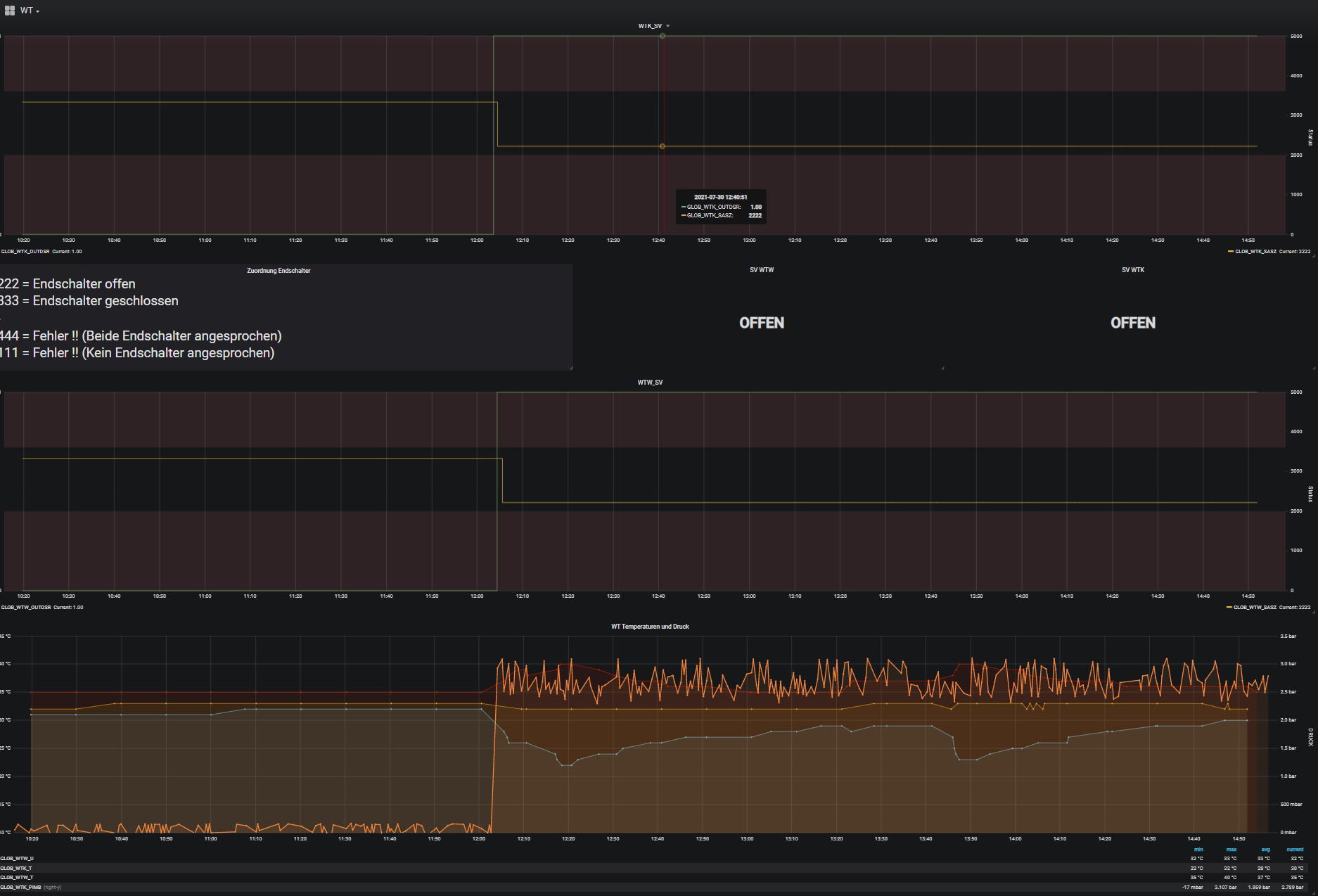
All logic is outsourced to the main controller in my smart home ( https://hackaday.io/project/14862-diy-scada-smart-home). Thus it was easy to visualize the state of the valves and add some smart functions. For example, use the temp sensors (temp difference to ambient) to determine the water flow in the pipes. In combination with other functions, the smart home knows when water is needed and when not. If a flow is detected when there should be no flow the valves close.


 Kenji Larsen
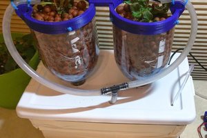
 Evan Salazar
Which geared motor and inductive proximity sensors are you using?