 SAYANTAN PAL
If you are working on a portable electronics project, or in a remote place where you can’t bring your bulky bench power supply with you, then powering your circuit becomes quite challenging sometimes. To power our projects we often use Lithium ion or Li-Po batteries. These batteries are convenient to use because they are small, rechargeable and often come in various shapes & sizes. But the issue with these batteries is that most of these batteries are rated for 3.7 volts and a maximum of 4.2v. Now for our application we generally need either 3.3v or 5v because typical microcontrollers and sensors work on these voltage levels. So in order to get the right voltage you either need a buck converter or a boost converter. Then we also need a charging circuit to charge the battery. So all and all you need some additional circuitry in order to use this kind of batteries.
At this point you might think why should we bother with all these and why not just use a powerbank then. It’s portable, can output 5 volt also it’s rechargeable. And yes, we could use a readymade powerbank to power our projects but there comes another problem. You see, those commercially available powerbanks require a minimum holding current typically 100mA to stay on. Now if you use deep sleep in your circuit to save power then the powerbank can no longer work properly. Because in the deep sleep stage the microcontroller consumes very less amount of current which usually falls under the minimum required current of the powerbank. And thus it turns off automatically after some time as the device enters into deep sleep.
So keeping these things in mind I started working on this project to make a trusty portable power supply unit that can power my projects uninterruptedly.
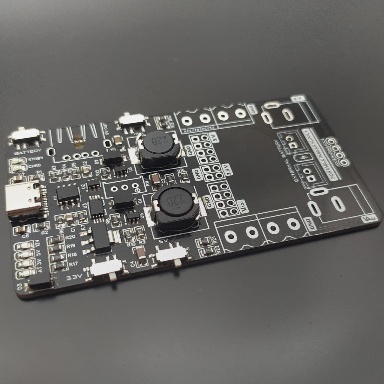
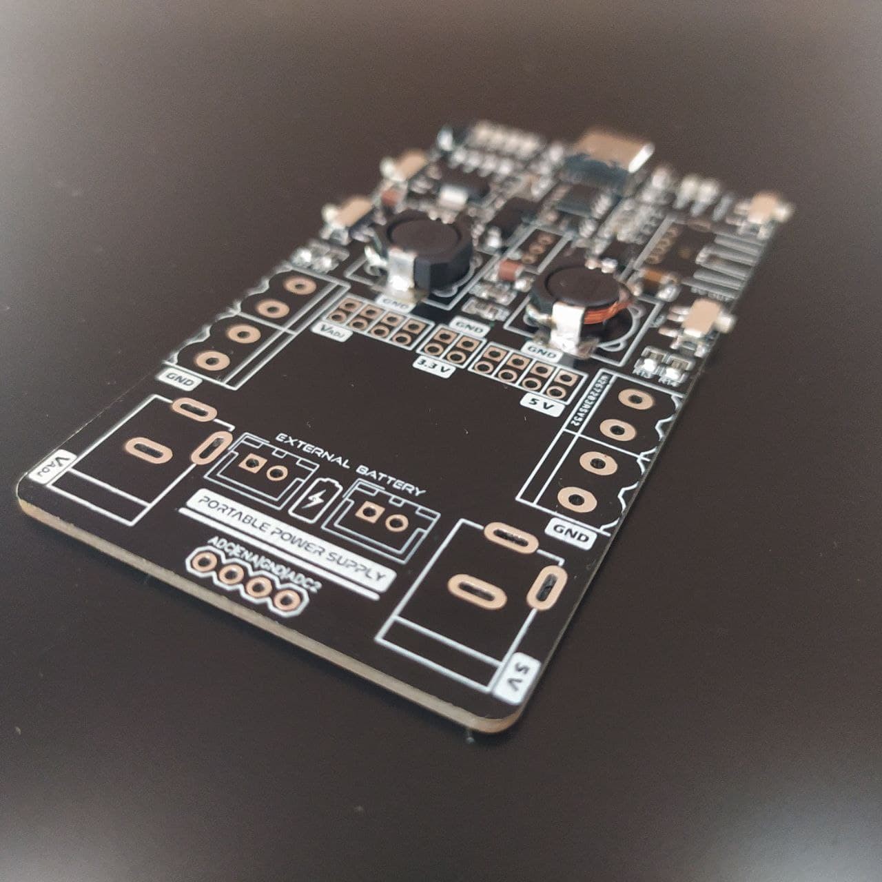
Let’s have a closer look at what we have in this circuit. We have separated outputs for 3.3v, 5v and an adjustable voltage output which basically fulfills most of our power related demands. We have both USB type-C and micro USB port for charging. It runs on two 18650 li-ion batteries which gives us about 5000 mAH of battery backup.
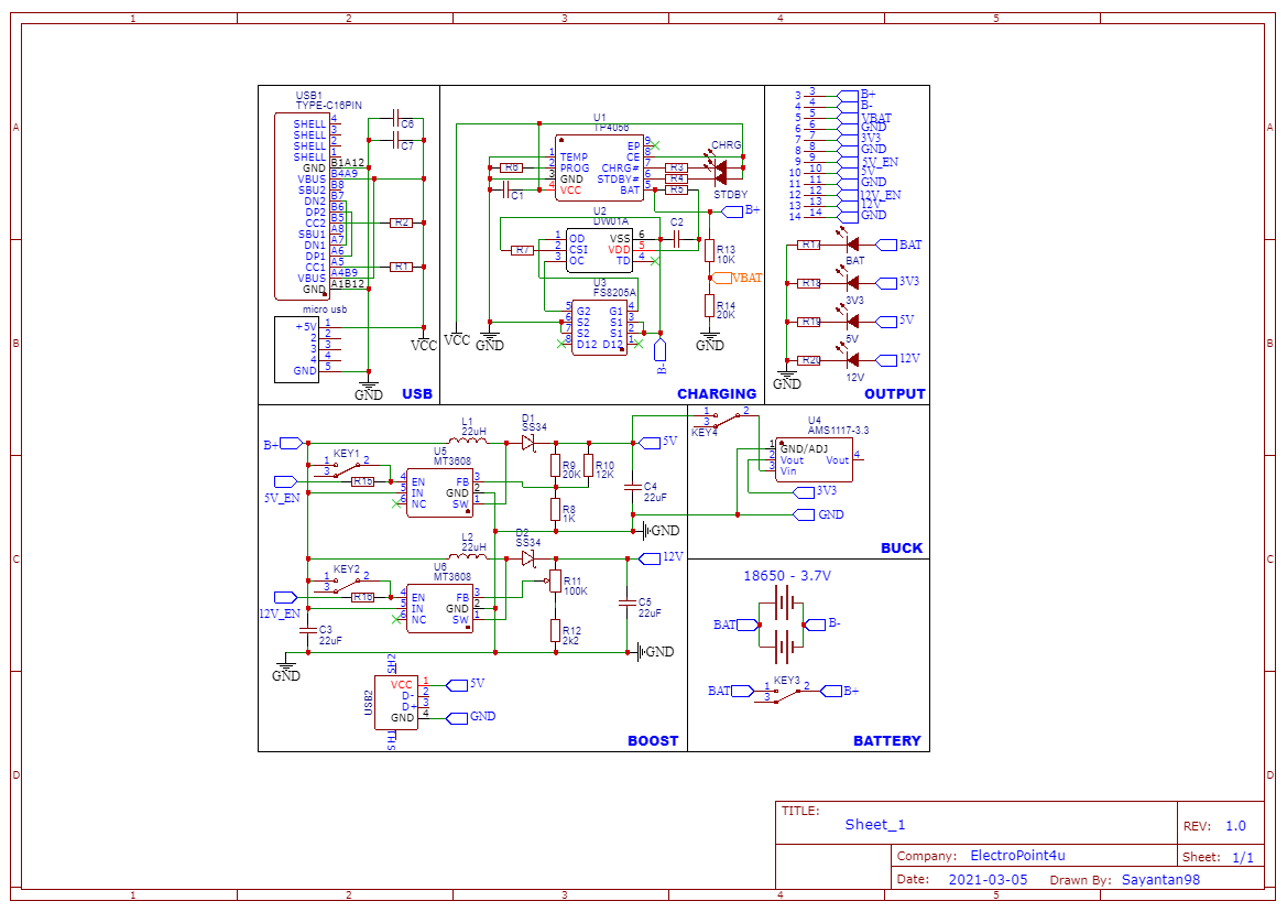
This is the schematic of this project. Here we have a TP4056 battery charging IC. And as you might already know TP4056 in combination with DW01A and FS8205A provides all kinds of battery protection features. Such as overcharge, overdischarge, short circuit and reverse polarity protection. Then we have 2 MT3608 boost converter circuits for 5v and adjustable voltage output. And an AMS1117 LDO to get the 3.3v output.
After assembling the board I first inserted the batteries in it and started charging it. It took me around 2.5 hours to fully charge the batteries. Then I check how much current it consumes when it’s in standby. And it shows me around 1.8mA. And you can get even lower by removing the indicating light. Then I turned on the outputs. So in this module you can turn on or off each output by using respective switches and the LED will indicate which one is turned on and which one is not.
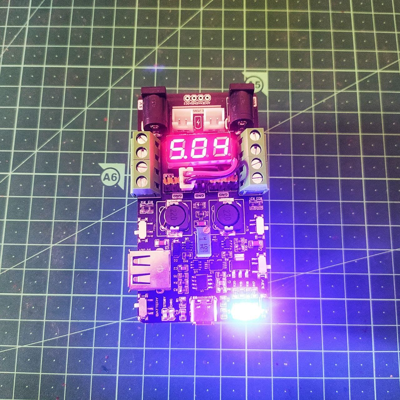
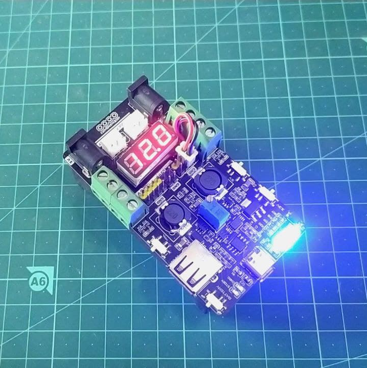
After testing the output we get a promising 5v from the first boost converter circuit. And on the adjustable side we can get upto 13v. Although we can get upto 28v as per the datasheet by using a 2k2 resistor and 100k pot but I keep it limited to 13v by using 470 ohm resistor and 10k pot because I don’t need that much voltage. I also added a tiny voltmeter to show the adjustable voltage readings.
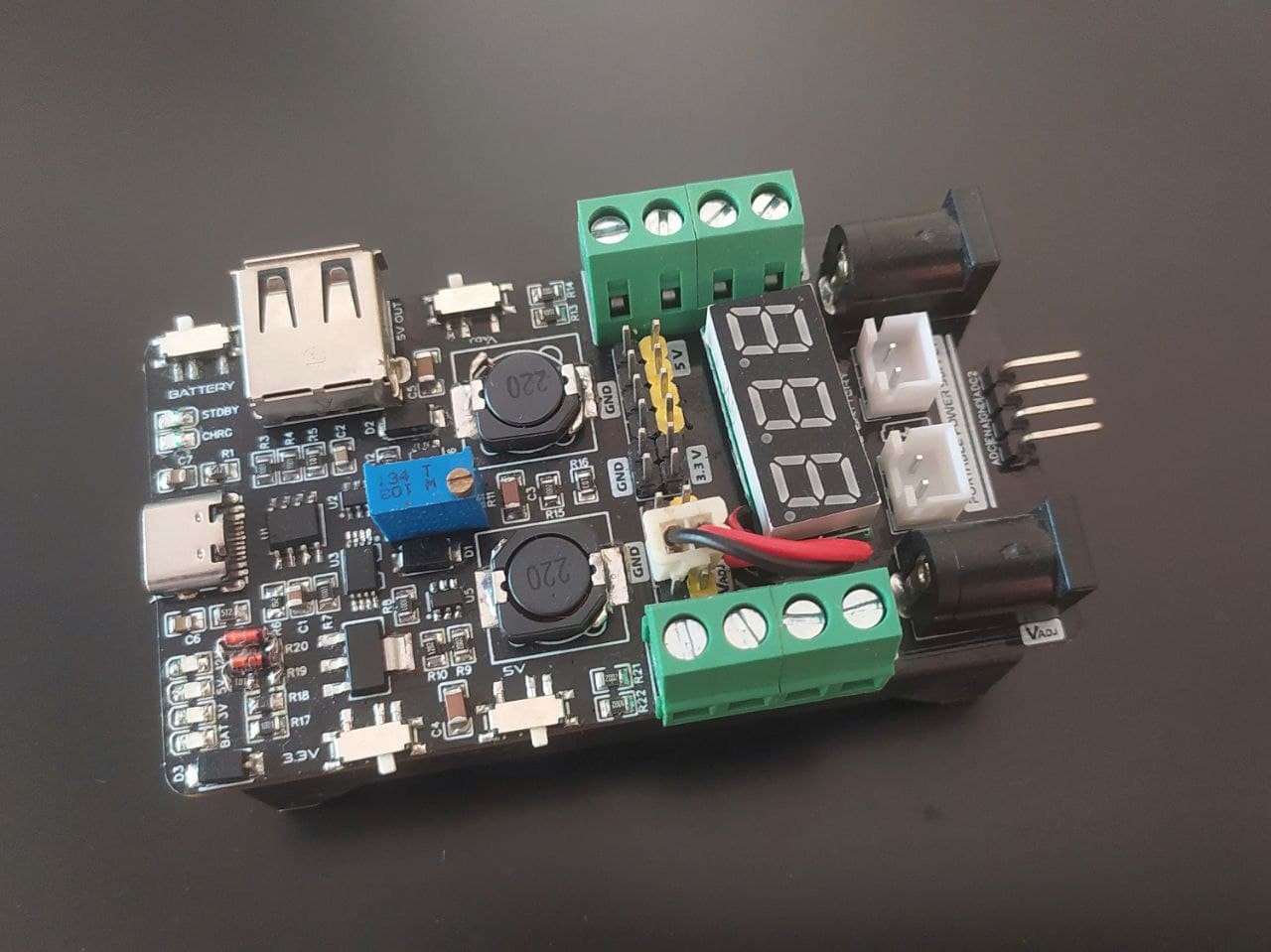
We can get the output from the screw terminals or from the DC barrel jacks as well as from the header pins and for 5 volt output we also have a female USB connector so you can plug any usb device directly. We can also connect some external batteries to the included JST connectors to charge/use them as well.
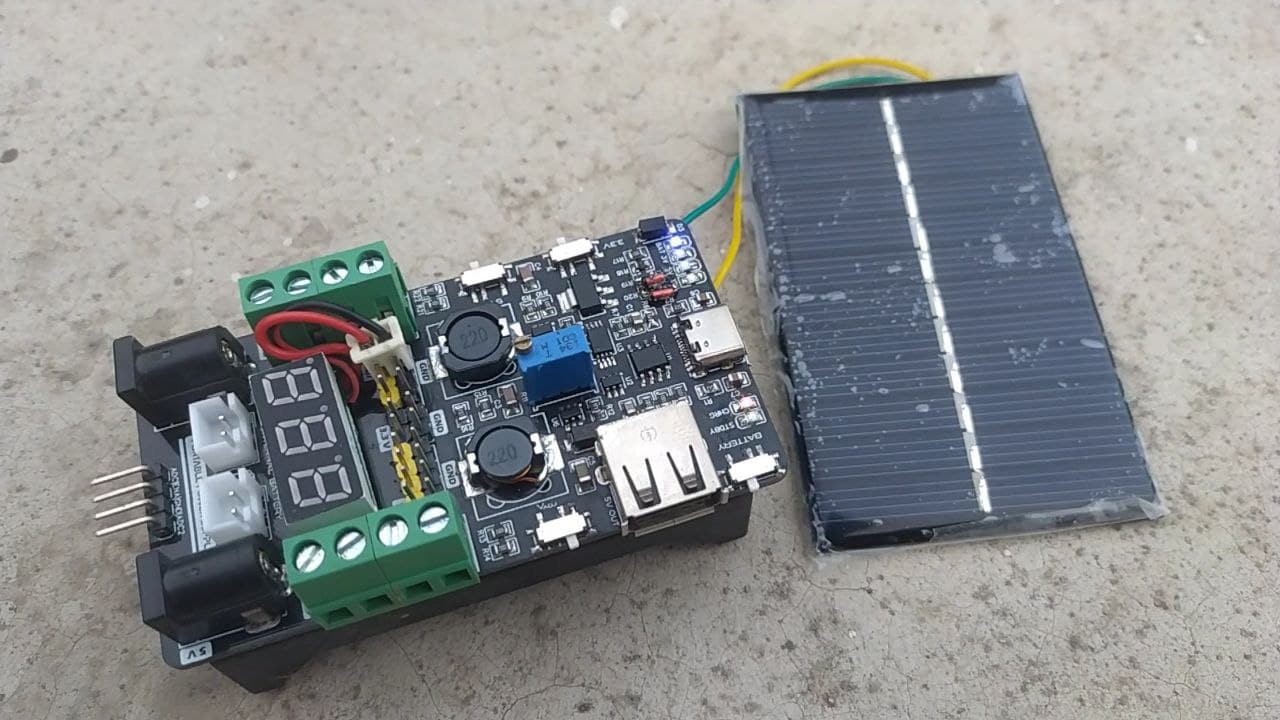
Now I was curious about whether we can charge it by using solar panels or not as tp4056 also supports that. and as it turns out we actually can!
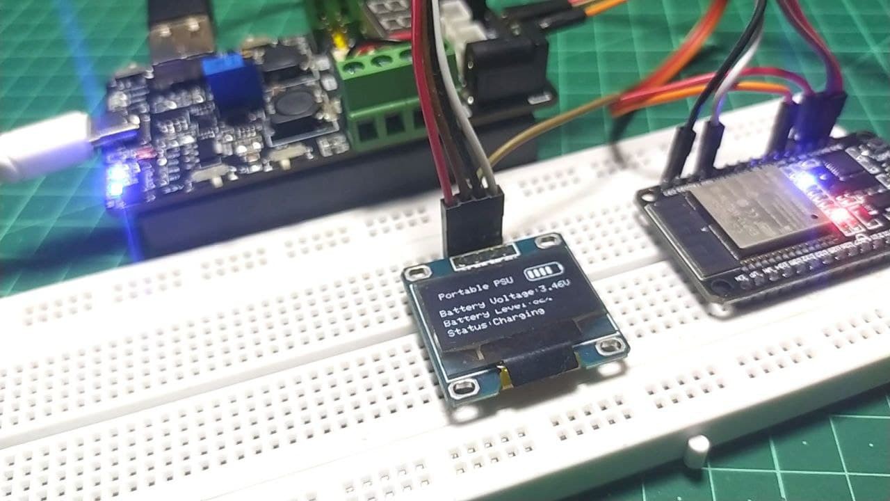
Last but not the least, when working with microcontrollers you may need to measure...
Read more »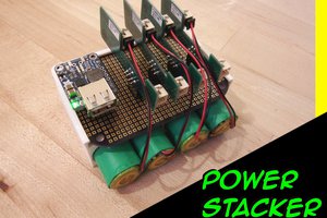
 isaacporras
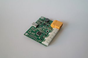
 Alex Klimaj
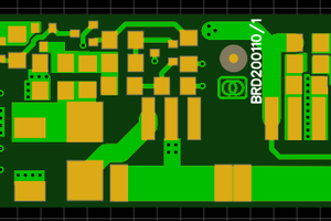
 Christoph Tack
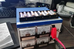
 David Scholten