Close
0%
0%

PROJECT-A

5 Axis articulated robotic arm. Actuated by planetary reduced open-loop stepper motors.

Similar projects worth following
5 Axis articulated robotic arm. Actuated by planetary reduced open-loop stepper motors. The bearings encircle the planetary reducers for a more compact design.

This was our first big robotics project, we learned much. We can still make a lot of improvements, but if we make the next improvement. We can throw away all of our parts, so we are finishing this project. The project so far is about 800€

The documentation is far from perfect because we just scraped some pictures and videos together trying to create instruction. Because this is poorly documented we don't recommend starting this project without a clue what you're dealing with. Dangerous electric power, some money, annoyance.


ATTENTION: Due to these plastics used in FDM manufacturing stress relaxation and creep is inevitable, therefore causing catastrophic failure of the arm, during or not during operation.

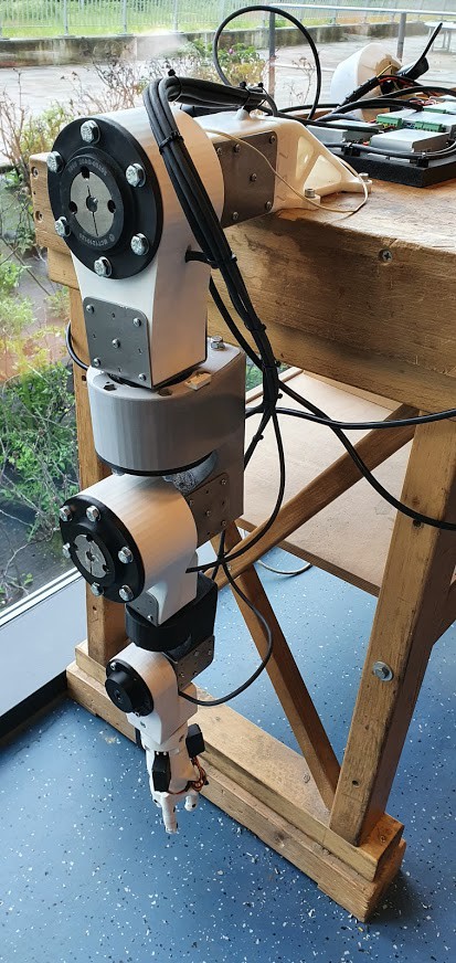
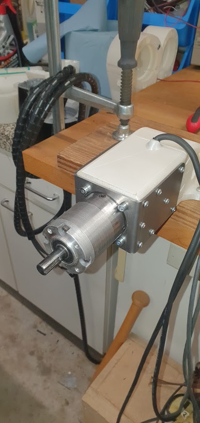
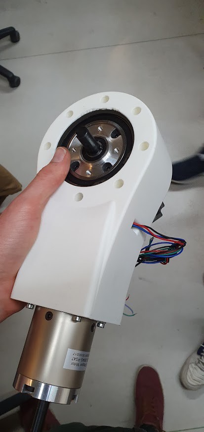
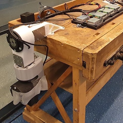
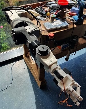
Actuators: The upper arm motors are NEMA 23 76mm with a DM452Y driver. For the underarm motors NEMA 17 48mm with DM420Y driver. 

Problem 1: These motors don't give position feedback so you just have to assume that they are in the position that they should be in. A few reasons why they could be in a different position than they should be in for example UnderAmpere, Overpressure, EM interference. For many cases, an open-loop configuration is reliable enough. But they still need a zero position some methods are end stops and hard stops. we use an end stop in our case a reed switch.

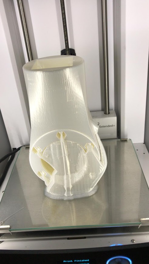
Problem 2: One other disadvantage of open-loop stepper motors is that the ampere isn't dynamic, what that means is that the ampere doesn't change under any conditions those conditions may be that the rotor doesn't co-align right with the stator. because the ampere isn't dynamic the motor generates more heat. That heat must escape our design isn't ideal for heat transfer for the motors. Mostly because there are 10mm plastics surrounding the motors. We tested for a few hours and the temperature is tolerable, but it's not great for the motors.

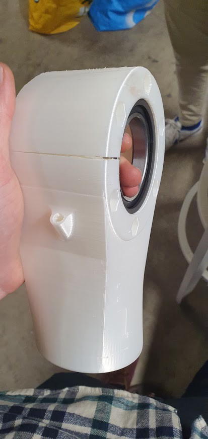
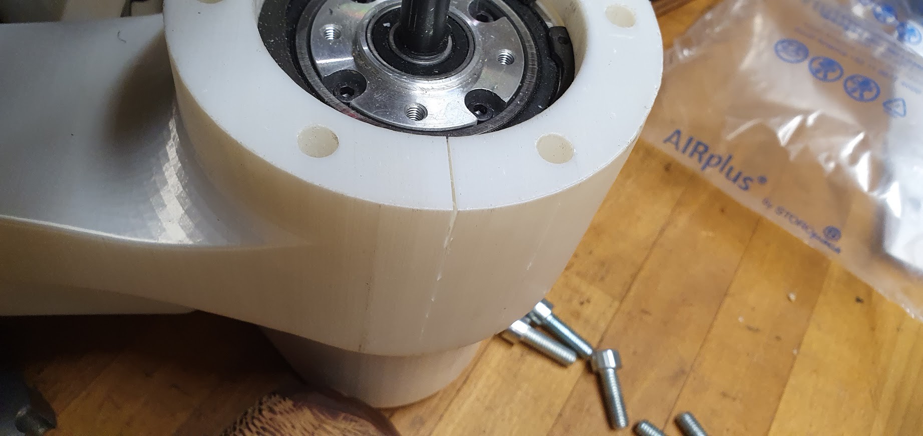
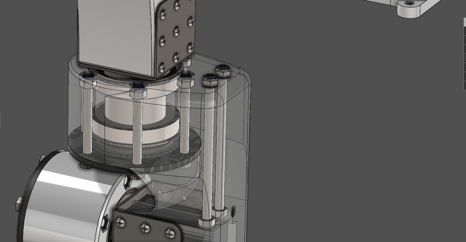
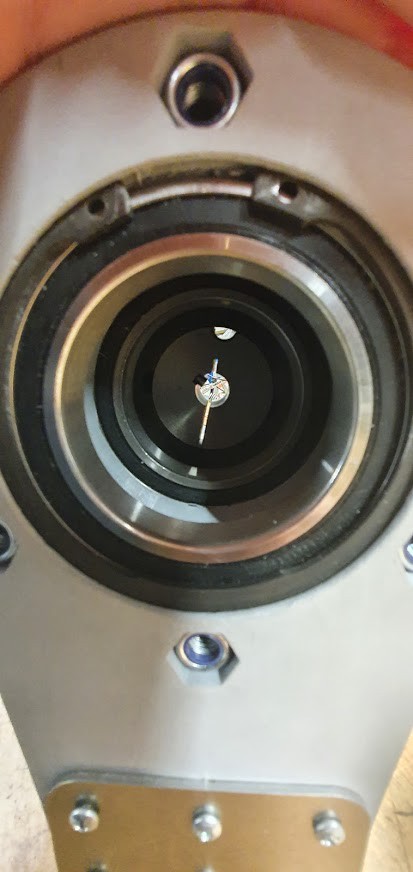
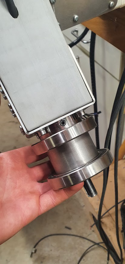
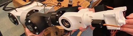
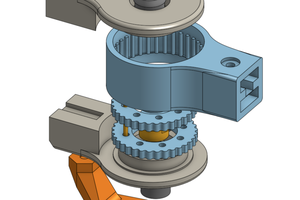
Bearings: The bearings are deep groove ball bearings. On axis 2 the force are almost all axial forces which the bearings are not suited for, so I don't think that's going to last long. Angular Contact Ball Bearings, are more suited for this joint. The only problem is, is that they're expensive compared to Deep Groove Ball Bearings.

Joints: On the stepper motors are planetary reduction gearboxes that reduce the rpm and increase the torque. We chose a cheap gearbox that comes with some downsides like low efficiency, heavy, and high backlash. We encircle that gearbox with bearings so the reducer sits inside that joint for a more compact design.

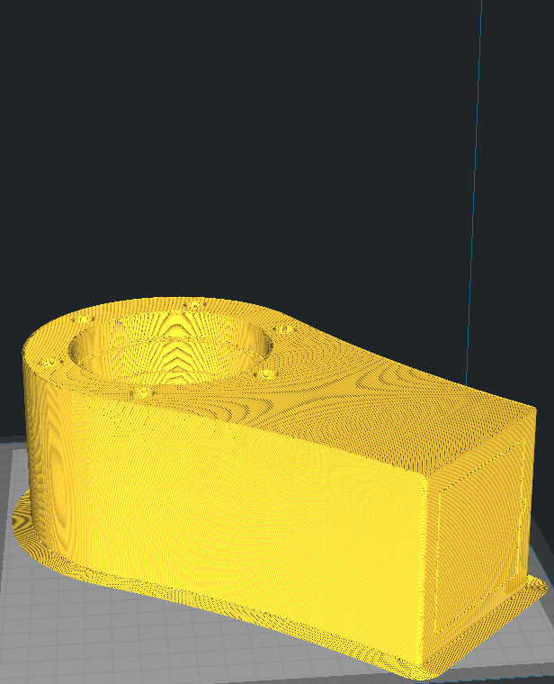
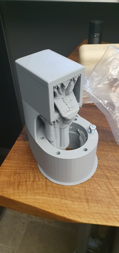
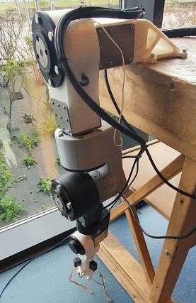
Problem 3: Because 3D print isn't strong enough to hold the weight of the motors and reducers we need reinforcement. We used 2mm thick sheet metal to hold the motor and reducer sturdy.

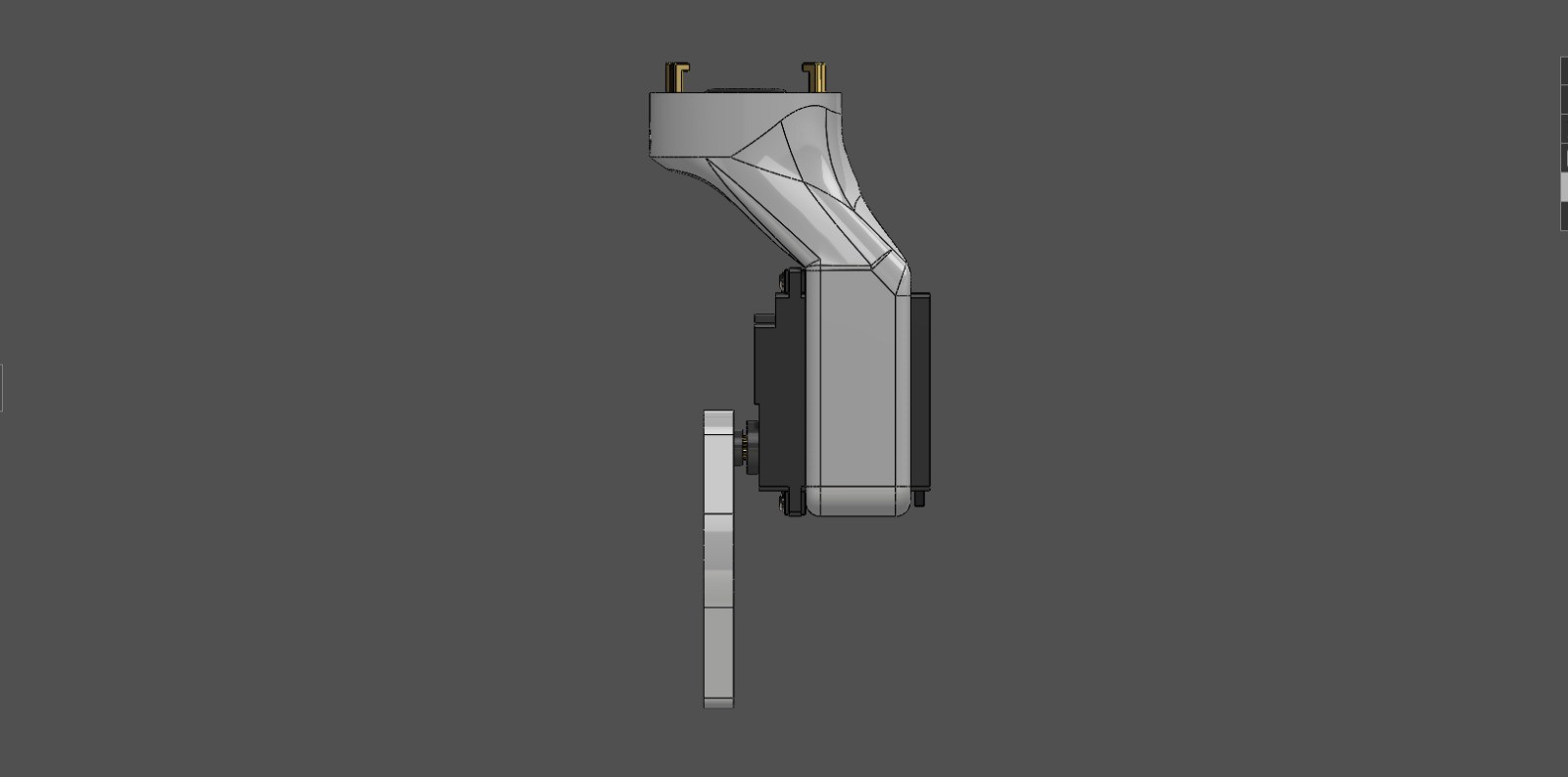
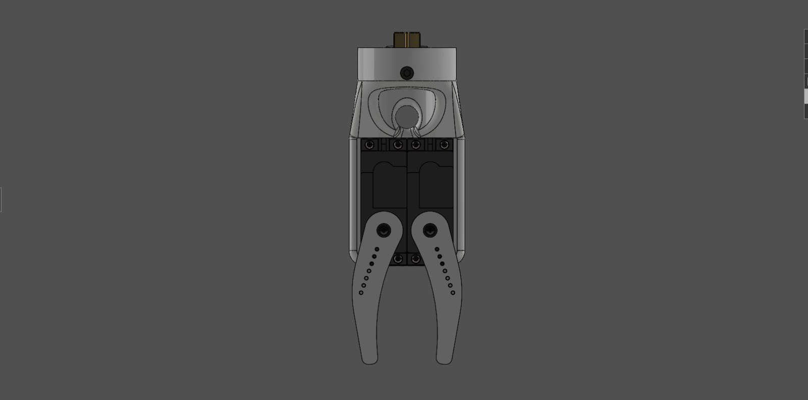
End Effector: You can design your own end-effector, maybe a suction cup, electromagnet, or laser. We already made an end effector that one is a 3 finger hand actuated by three servos.

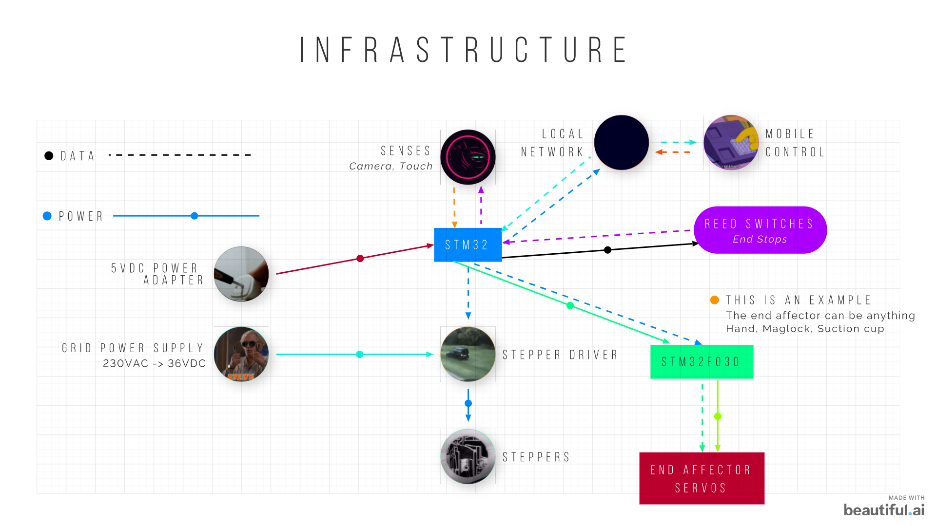
Infrastructure: The end effector is an example, the configuration of the end effector is the one we use ourselves now. The separate stm32f030 is there for minimizing cables to the end effector, and because we are more flexible with what end effector we put on.

x-zip-compressed - 29.03 MB - 06/22/2021 at 18:34

Download

View all 27 components

  • Finished

    Sixth_Nassau06/28/2021 at 21:06 0 comments

    It's finished


  • New Hand/Gripper

    Sixth_Nassau06/22/2021 at 18:33 0 comments

    Way simpler design, it only consist of three 3D printed parts so that's convenient. Because the servo's are quite strong about 2.47Nm, I'm pretty sure they'll crush every paper cup you put in there.

  • Still Looks Cool

    Sixth_Nassau06/04/2021 at 18:48 0 comments

  • All 5 Axes

    Sixth_Nassau05/27/2021 at 17:48 0 comments

    This one shows self-power off, by pressing the kill switch. Always handy for certain situations.

    Let's See

    Still surprised that 3D print can handle such loads. Especially where the base is located. All the force of the 16KG arm is supported at the base by a small area in which the cross-section is equal to 60cm² or 77x77mm.

    Here you see all 5 axes moving simultaneously.

    The length of the arm is 667mm from the center of the first joint to the coupling of the end-affector. With the end-affector (in our case a 3 fingered hand) attached it is 850mm from the center of the first joint to the grip area of the gripper.

View all 4 project logs

  • 1
    Order Everything

    Omc-Stepperonline: pretty straight forward just sign up, and order.

    Maedler: is a site where we order many mechanical parts. These parts are universal and available on many sites. https://www.mcmaster.com/

    Bearings: maybe it's locally available otherwise many sites are available for orderings these bearings, same goes for brass melting inserts, cables, and water hose connector.

    Sheet Metal: https://metalscut4u.com/carbon-steel, https://www.247tailorsteel.com/nl, https://csmfab.net/

  • 2
    3D Print Parts

    Some of these photos are of old parts so don't freak out if the given files don't look like them.

    For every joint 3D printed part, you need to make sure that the axis of the circle is always vertical, otherwise the forces of the arm snap the print. Like these photos.

    On the photos here under you see how it should be done.

    You can help see how to orient it by imagining it's a cup holder and the cup inside it must be up.

    The tolerances are tight so be careful with warping and all that stuff. 45% infill worked fine for us.

  • 3
    Assembling

    Base Assembly

    To maximize strength we inserted two 145mm long M8 studs to reinforce a 3D printed part.

    Joints: We tried to minimalize the support but it's hard with the constraints. When you're done printing you remove the support, which can be a real hassle with these designs. You squeeze the bearings in, then you insert the retaining rings. You need to be sure that the retaining rings are secure. To ensure the retaining rings are secure you can compare the shape of the normal retaining ring with the one you're inserting. If the two are symmetrical you can be sure it's properly secure. As long as you don't hear concerning cracks or see concerning cracks.

    To insert the motor into the printed part with the bearings and retaining rings you need to shave 1mm wall thickness of the planetary reducers to do that you need a lathe. Or find some other method where you can shave 1mm wall thickness of a metal piece.

    This isn't the best exploded-view for sure. But it gives you a mere idea of how we designed our joints. of course the retaining ring needs to be squeezed to fit inside 3D printed housing.

    We use both metal and plastic outer taper bush housings, because if you 3D print the outer housing the housing isn't strong enough to clamp to the inner taper bush, which causes additional backlash. That's additional backlash on top of what should be 90ArcMin. What's imported is because all axes have a lot of backlashes the end effector can move in an area of 50x50mm freely. The only way to minimize the result of the huge backlash is by limiting the motion of the arm in a way that gravity pushes the gears in one way. So refraining the motion makes the arm look better and act better than it really is. Almost all of the backlash is a result of the economy gearboxes.

View all 5 instructions

Enjoy this project?

Share

Discussions

Similar Projects

Does this project spark your interest?

Become a member to follow this project and never miss any updates