-
11. Build the base.
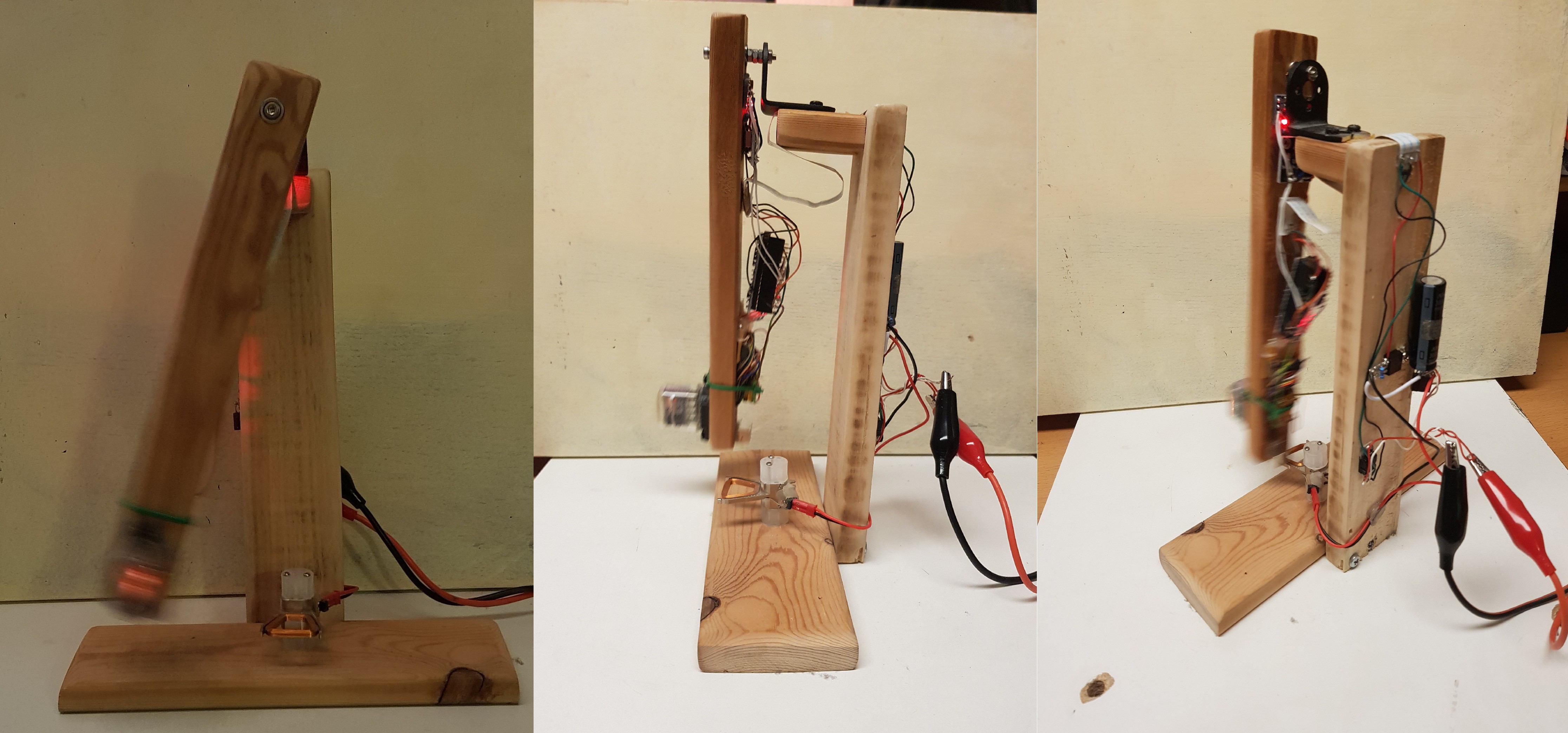
Connect all the wooden parts exept the arm with wood screws so you get a stand like this:
(Foot + stand + standof)
![]()
-
22. Mount the arm with 2 ball-bearings
b) Drill a hole centric in one end of the arm, so the ball-bearing fits in it.
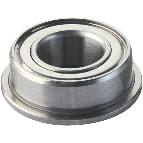
The ball-bearing looks like this:![]()
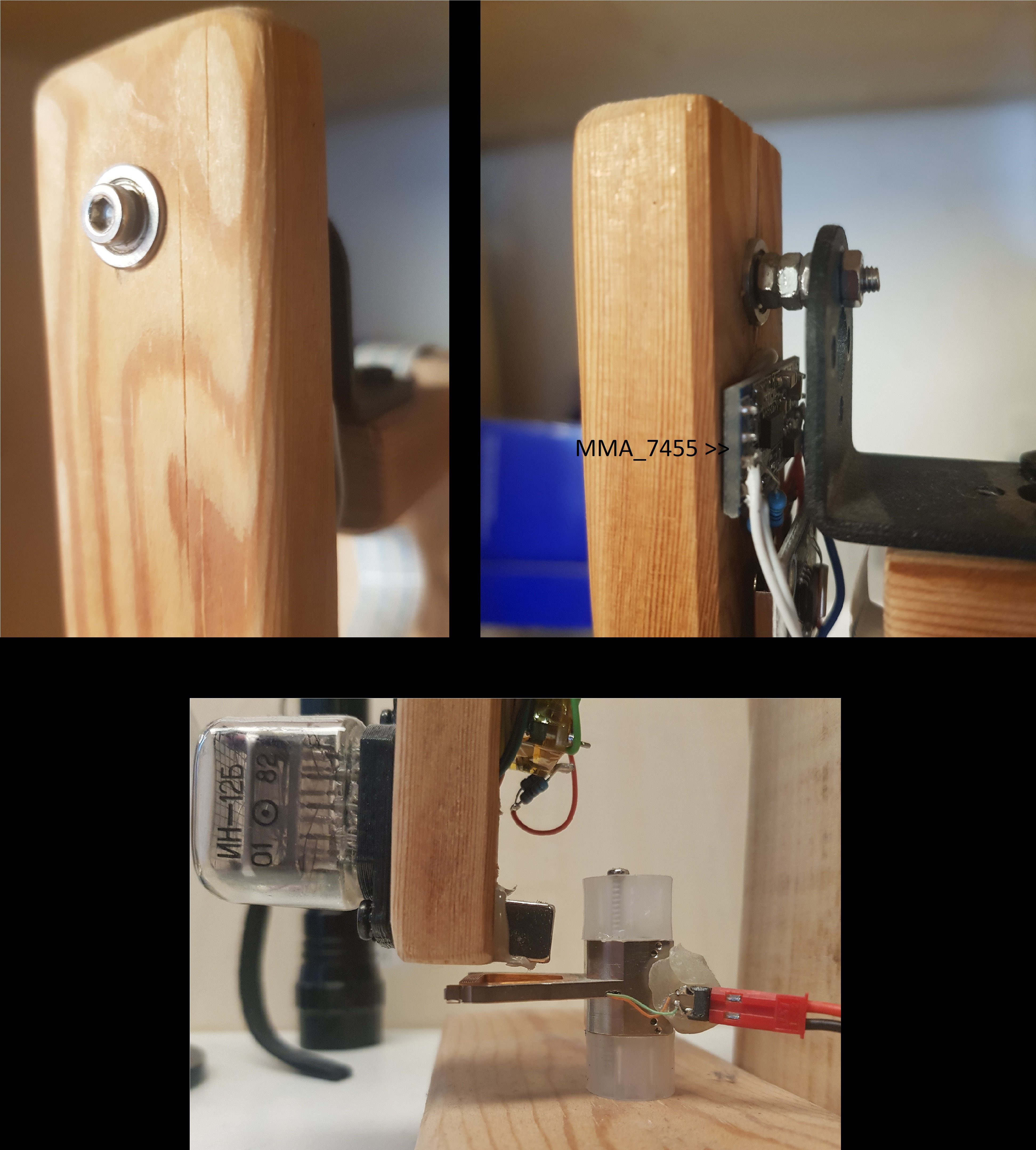
and they were stuck in both ends of the hole. A small but long M2 screw goes through the ball-bearings with got tighten by counter nut.
On the other end of the arm drill a hole for the cables from 74141 to nixie-tube.
On the front of the arm i used a Nixietube-Socket (https://www.thingiverse.com/thing:576723). I stuck in the nixie-tube and and after that i solderd the cables (10 Cathodes, 1 anode with 170 V - The currentlimmiting resitor shouls limit the current from 1-3 mA's). Then the socket gets screwd onto the front of the arm.
![]()
Now find a screw to mount the arm it on the small pice of wood (the stadof), or use a 90° aluminium angle to fixate the arm through the ball-bearing on the "too" long M2 screw.
If all went well: after you tip the arm it should swing very long and it will move for minutes!
-
33. Electronics and correct Magnet placement
See scheematic for wiring. Build the backside parts onto the backside of the stand onto the wood.
Build the "Pendulum" parts together and secure them on the backside of the arm. The Accelerometer needs to be as close to the axis (ball-bearings) as possible! Otherwise the centrifugal force will be more present in the meassurement than the gravitational force.
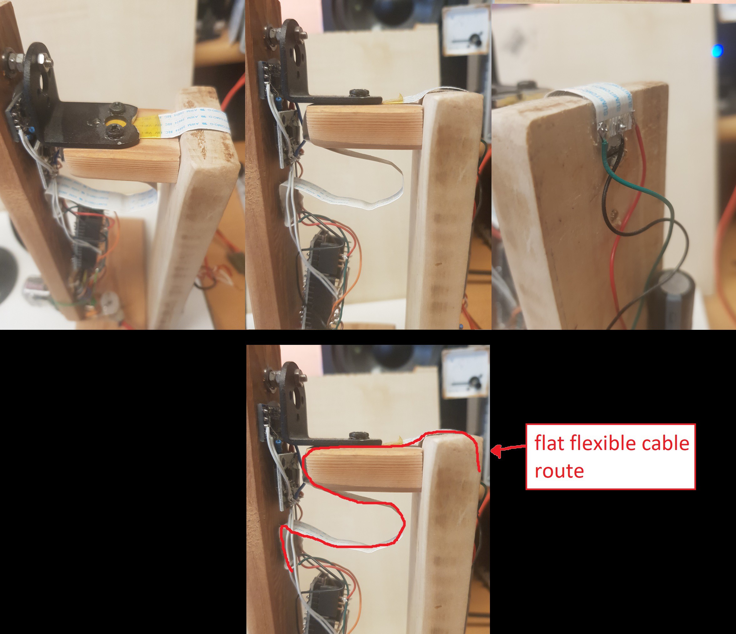
Find a way to secure the flexy-cable, from the boackside of the stand to the backside of the arm, while the arm still can swing freely, without much dampening of the swinging.
Now connect Ground, +5V and Coild-Trigger from D13 from the backside of the stand to the flexy-cable and on the arm from flexy-cable to the rest of the electronics.
![]()
Check every module on functionality (RTC, Accelerometer, Nixietube - all numbers)
Upload and set the RTC.
Now we need to get that pendulum keep swinging. Check if position: "arm straight down" equals 0° on the Accelermeter (MMA_7455). The Coil should induce a pulse on the magnet. See with some other magnet, witch two sides of the cubic magnet are the poles - one should attracht the coil and the other side should repell from coil - we need the repelling force configuration for this project. Mount the coil on the upside from the wooden foot and glue the magnet on the arm at the backside bottom position WITH: repelling force configuration / orientation!
-
44. Upload Code and calibrate
The code was there long ago (about one year).. but it was frustrating to calibrate so this project got shelved. First of all - after every upload i have to unplug usb and recable Vin to see your changes outcome.
Try to find the single minute position, when swinging from left to right AND from right to left.
Then tune "GradAbweichungvrnl" (Degree_difference_when_swinging_from_Right_to_Left) and "GradAbweichungvlnr" (Degree_difference_when_swinging_from_Left_to_Right) in the main loop of the frimware. see comments in code for more information. Dependeng on weight and exact length of the arm the swing-time (periode) will differ and must be tuned, so the numbers overlay when swinging from l2r and from r2l.
If you have come so far: well done !!
Ask me anytime for more information. I'll try to help out.
Nixie Pendulum Clock - Concept
A pendulum clock with a NixieTube (IN-12b) that plots the time in the air it passes.
 j
j


Discussions
Become a Hackaday.io Member
Create an account to leave a comment. Already have an account? Log In.