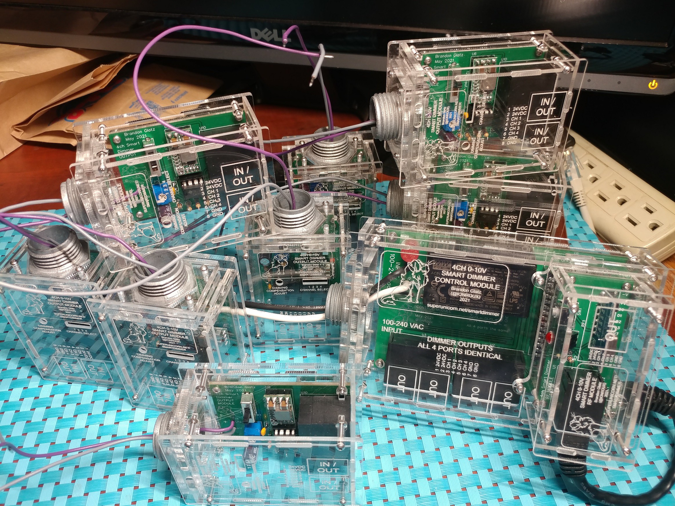
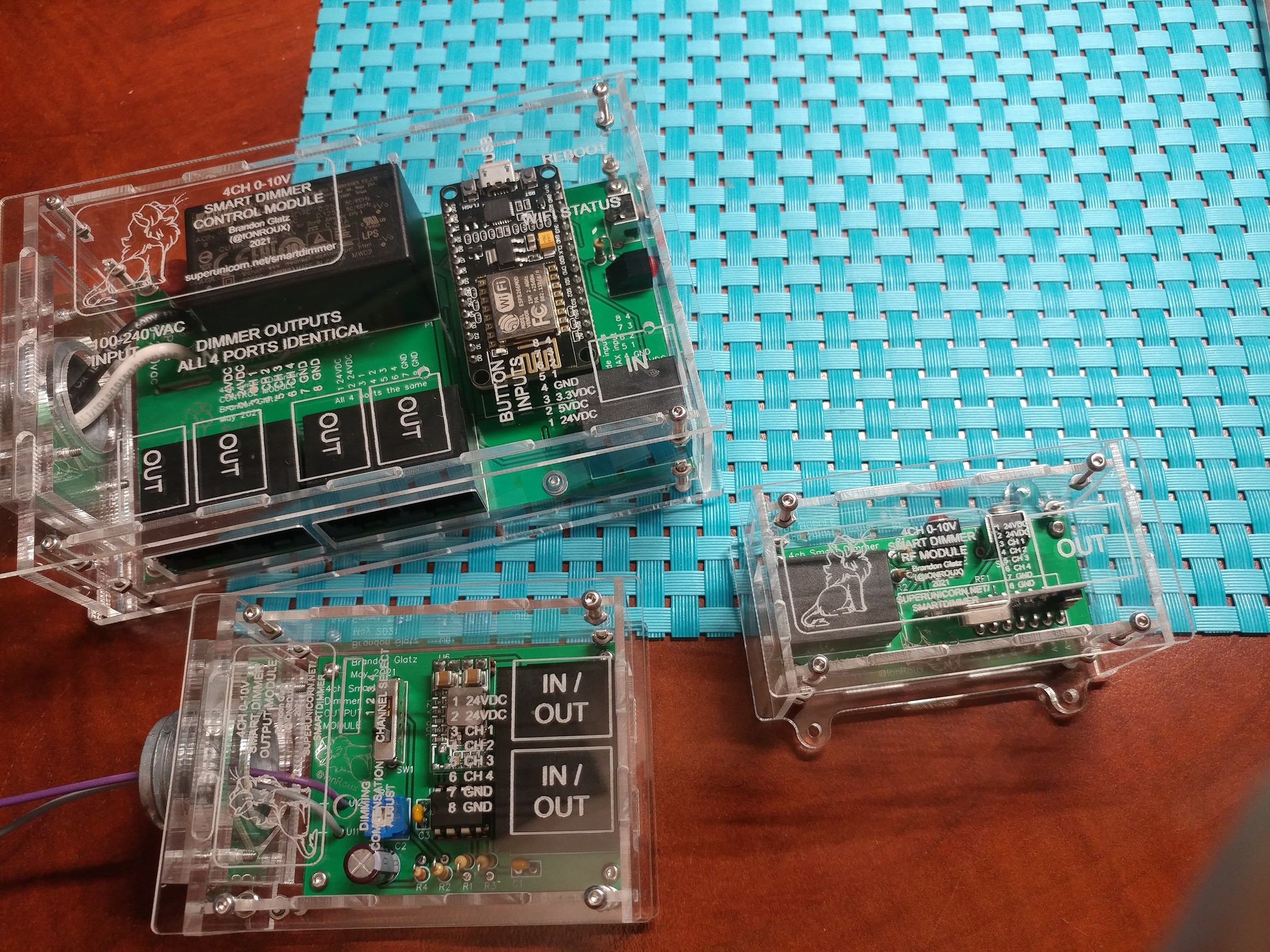
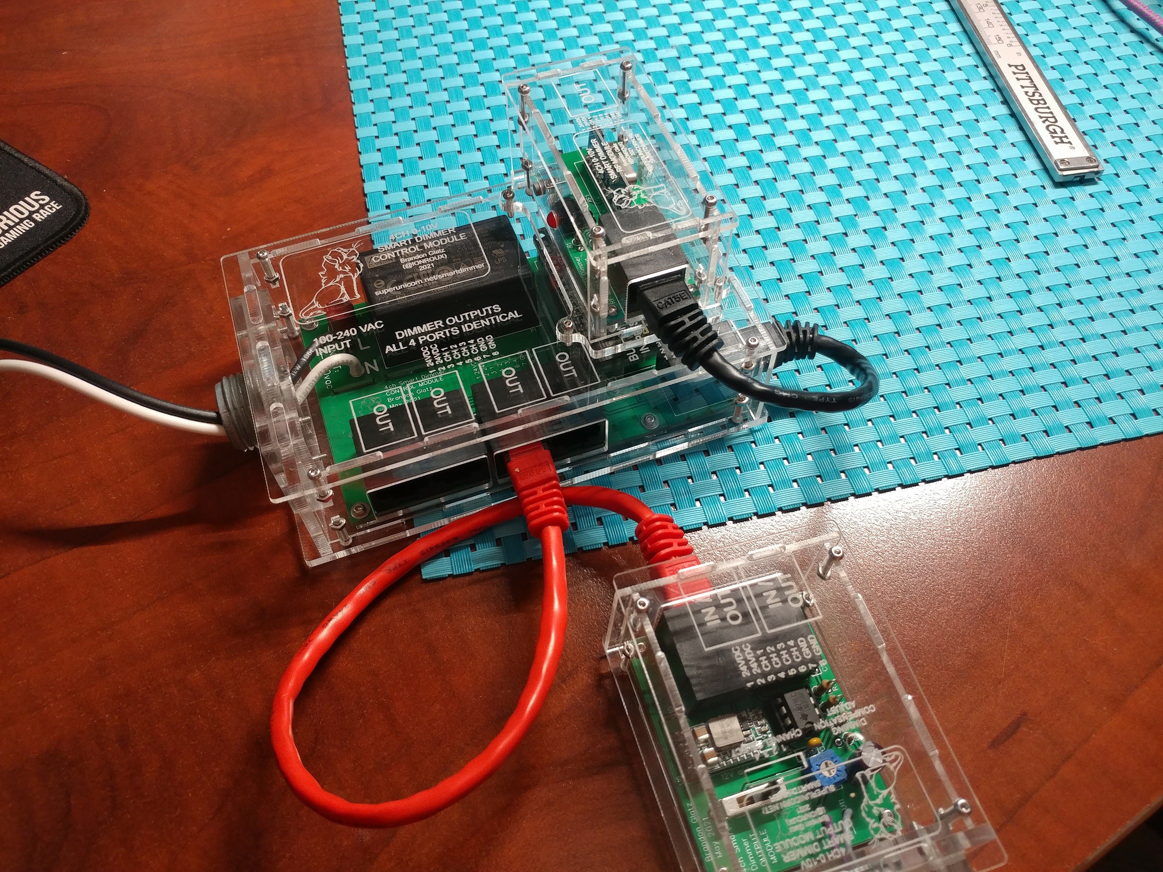
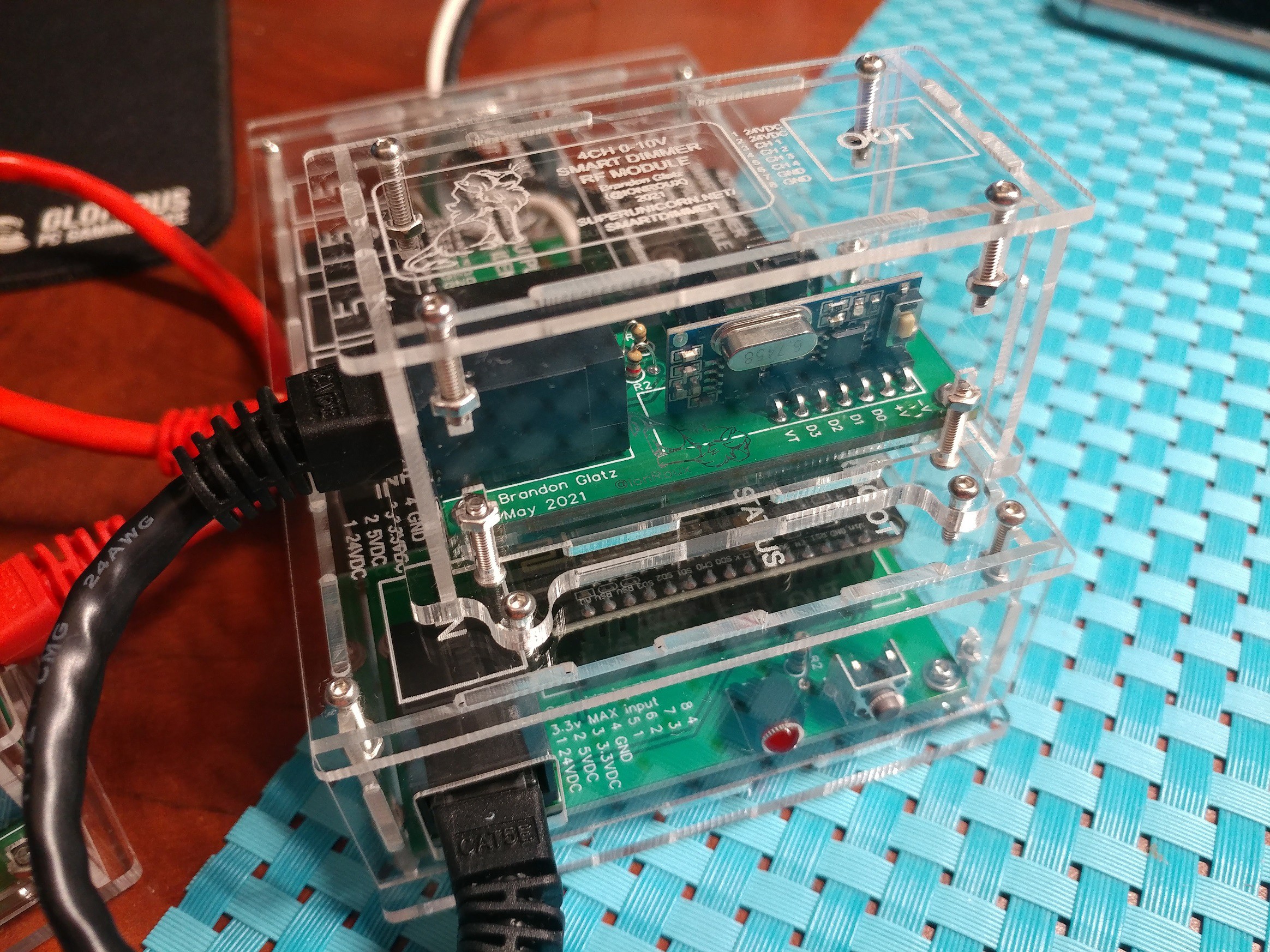
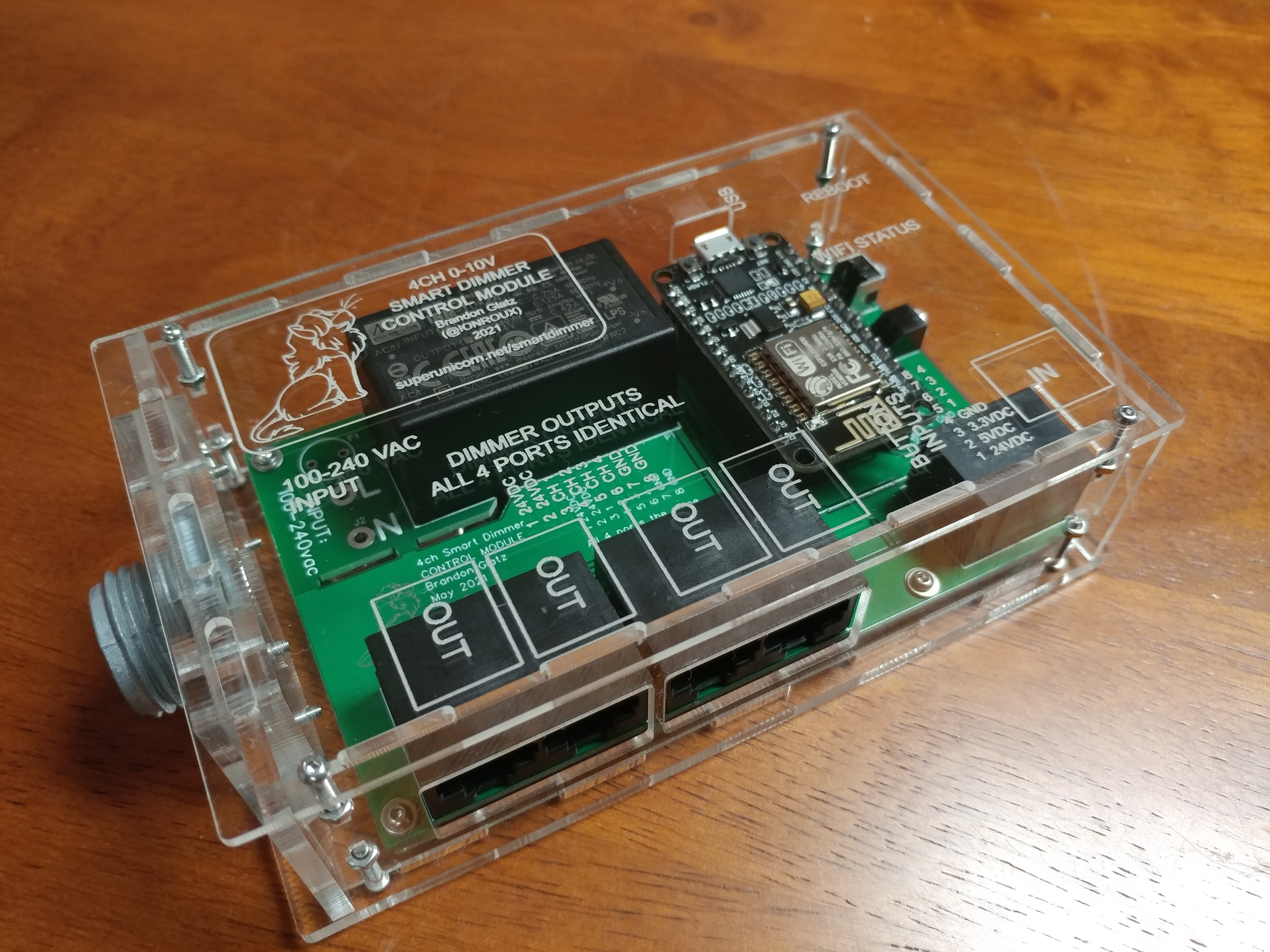
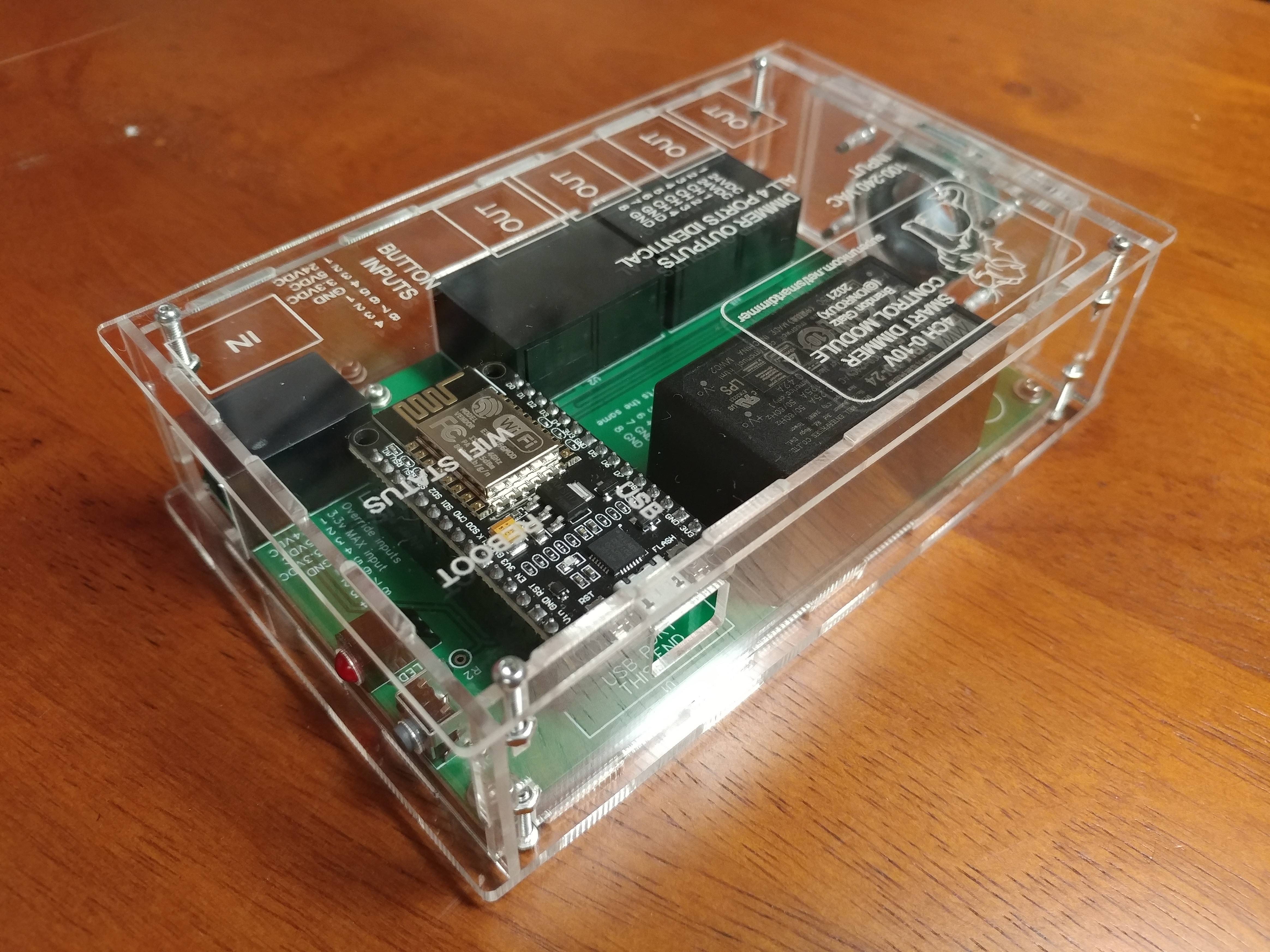
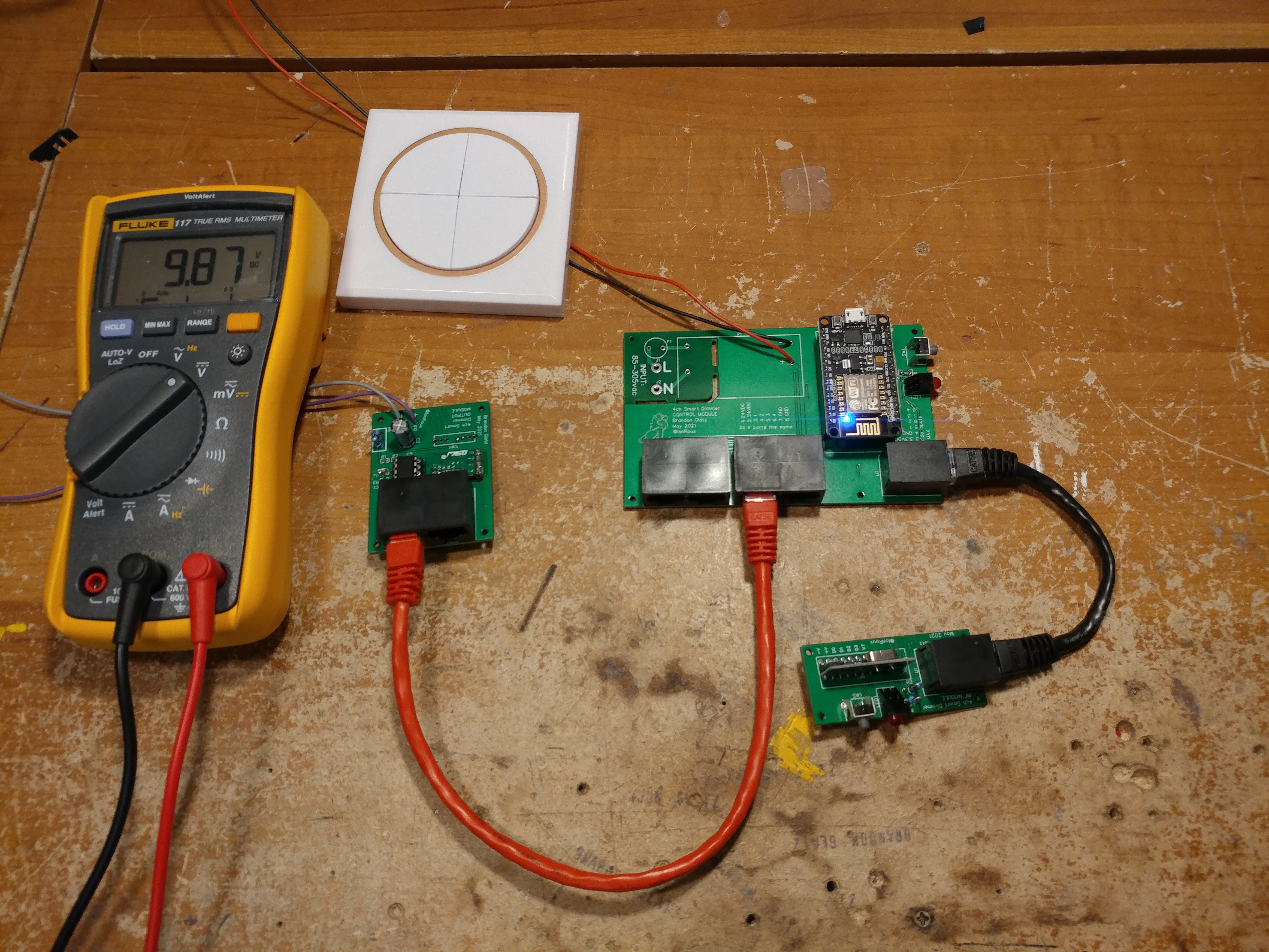
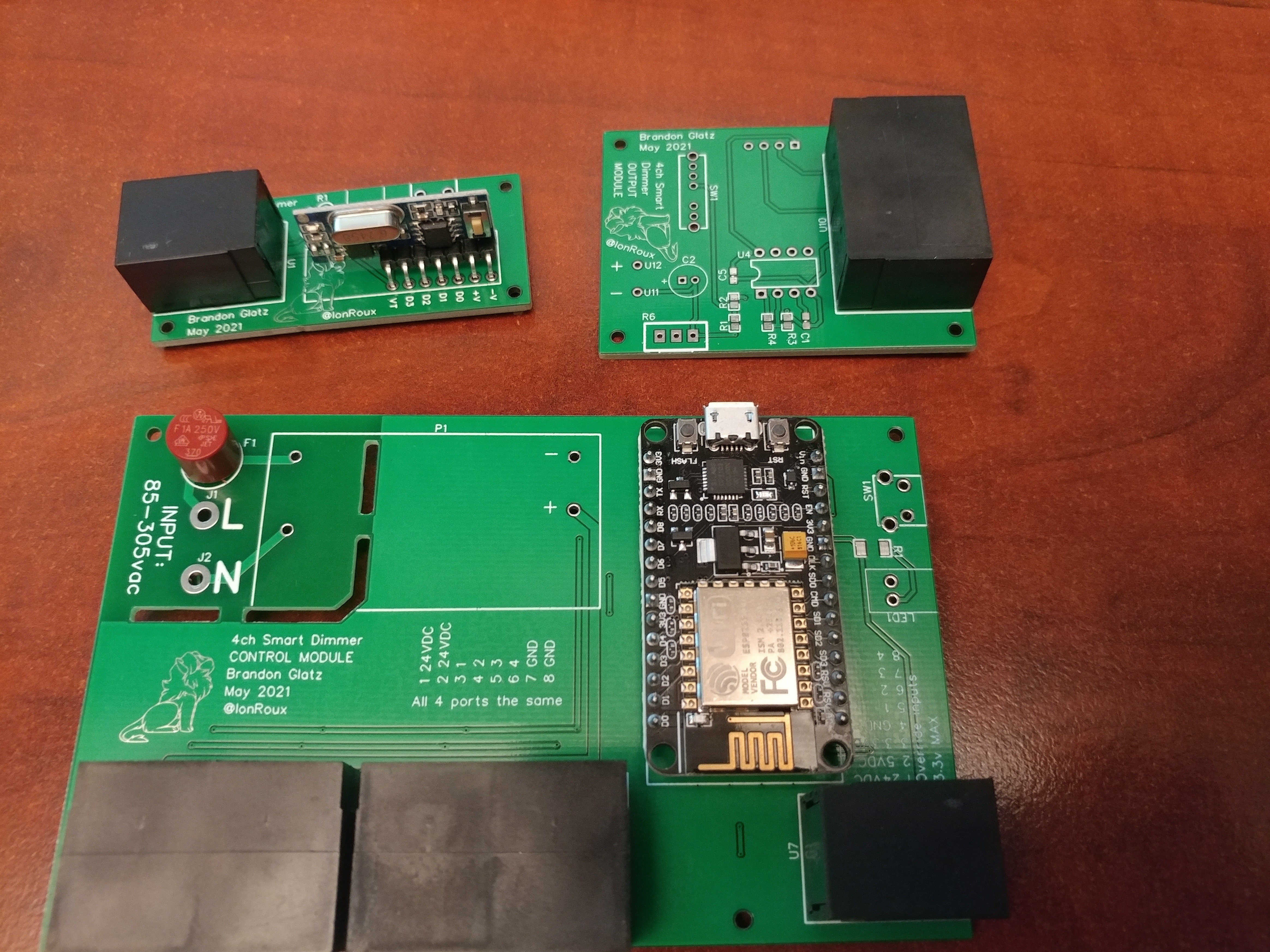
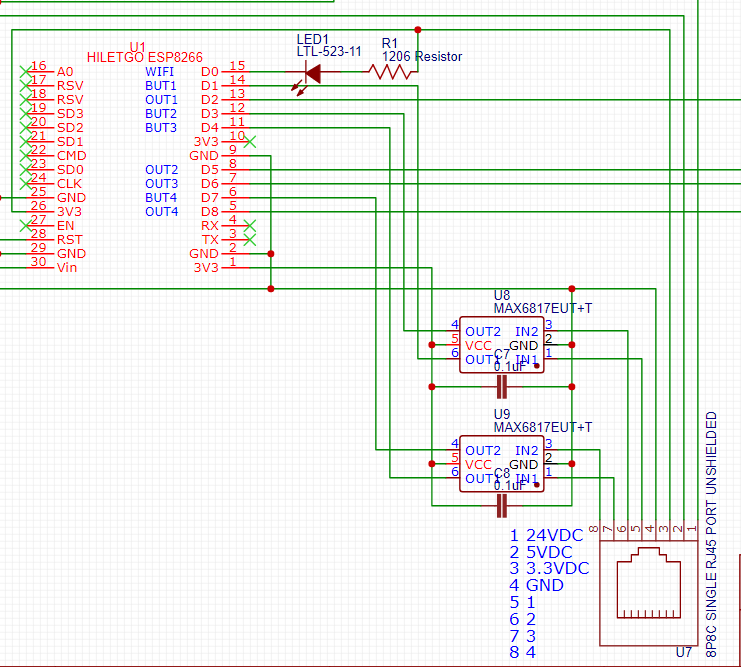
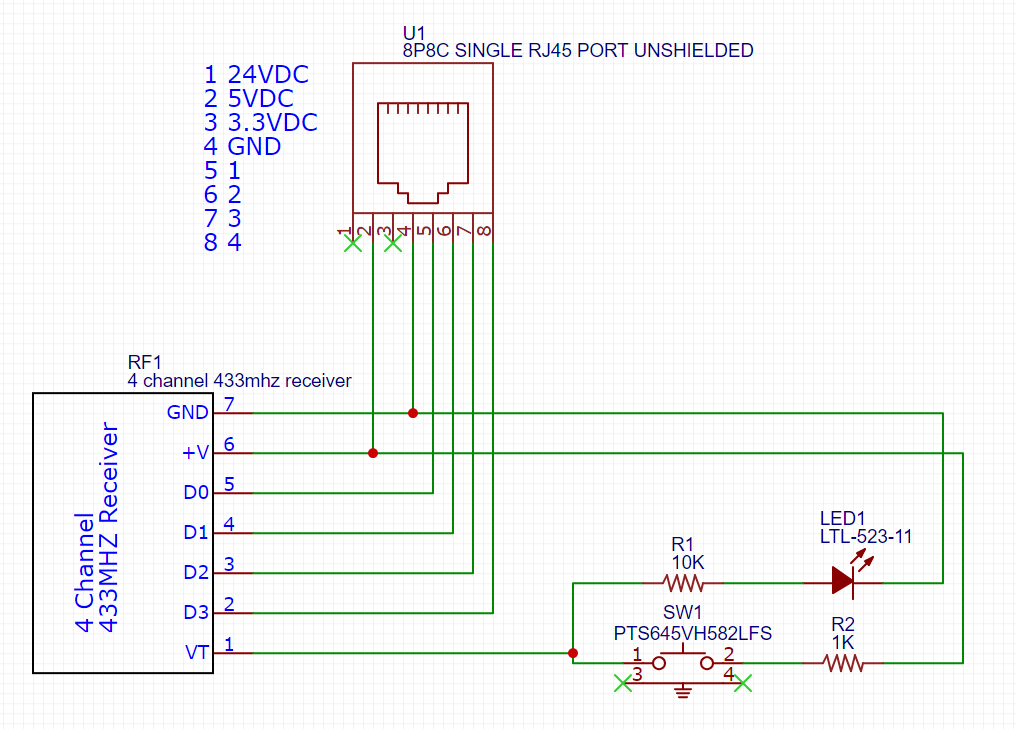
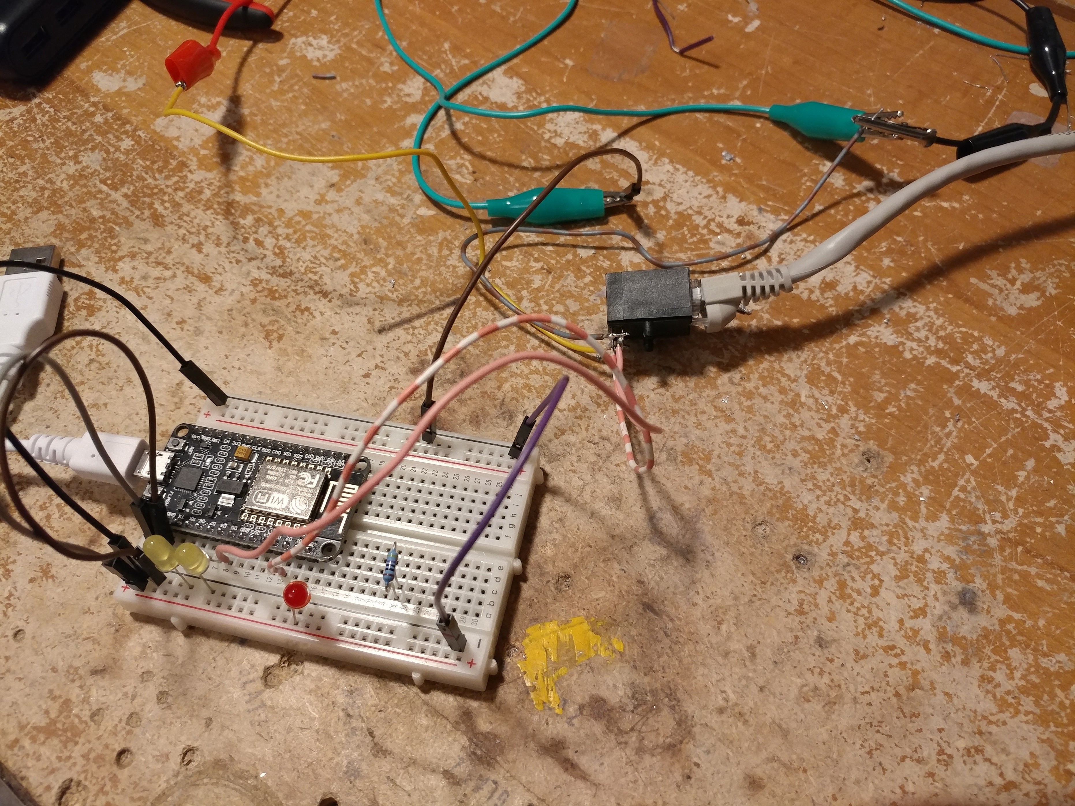
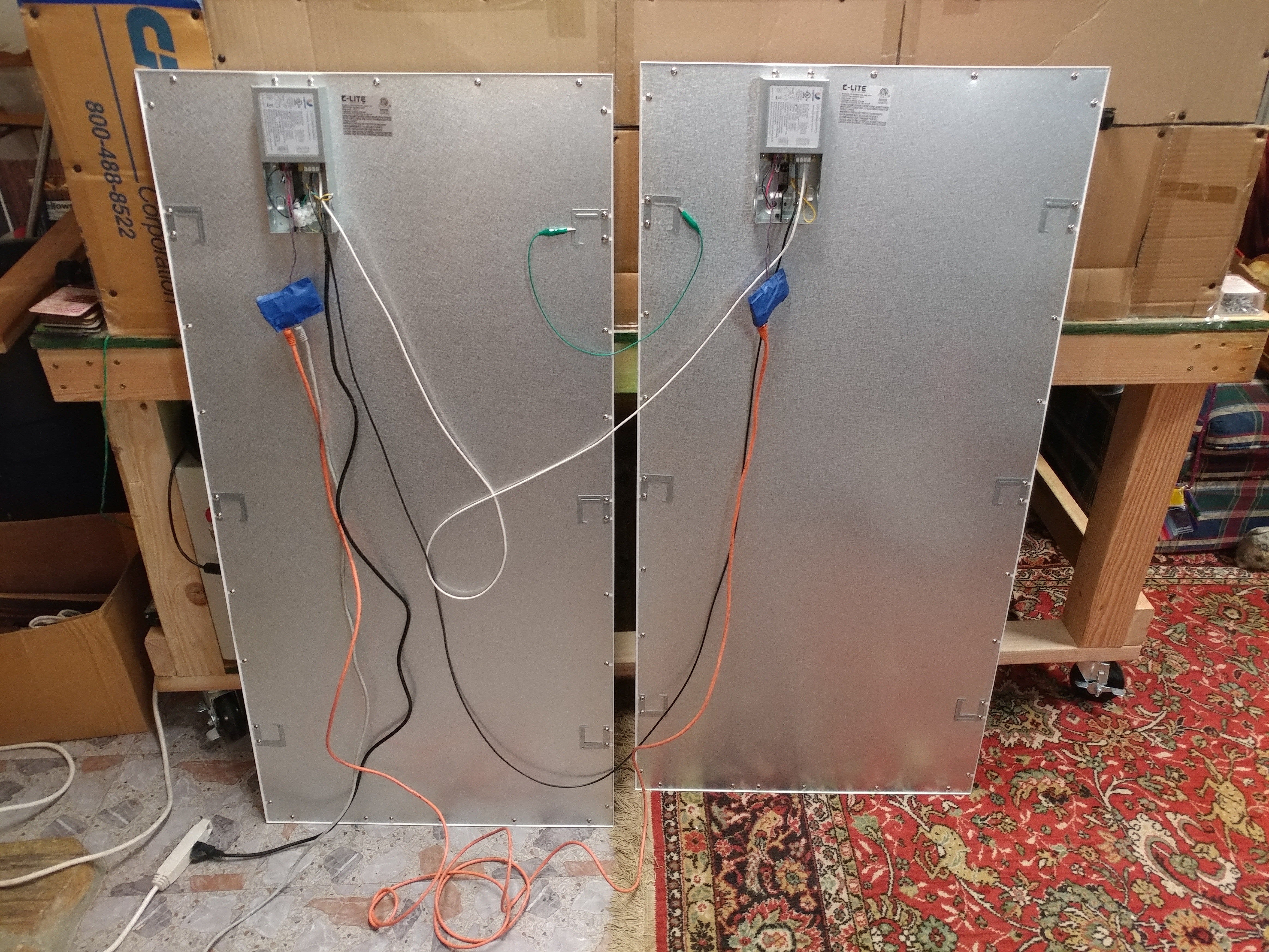
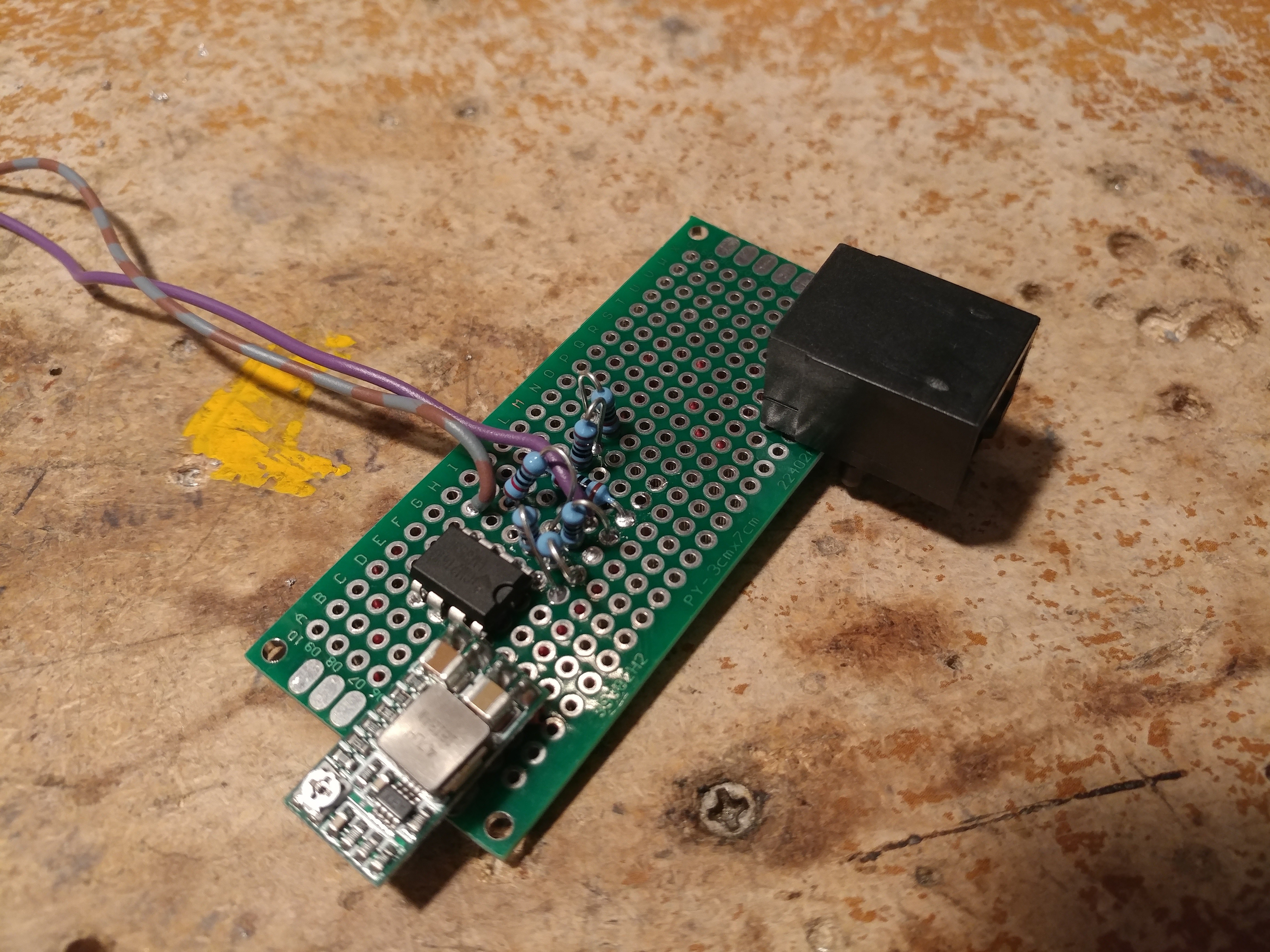
• Update on project

    brandon02/13/2022 at 01:07 0 comments

    I have been using these dimmer for some months. I have finally managed to get my hand on a google home and found that google homes do not work with generic smart devices. I attempted to set it up with IFTTT but either I could not figure it out or it does not support dimming things, but it seems like google home support with this is dubious at best. The code uses the ESPALEXA library for the ESP which doesn't seem to have a good way of interfacing with anything else.

    Few other problems is that the zero point adjust seems to drift. A few of my lights don't shut off decisively. It is annoying to go up in the ceiling to adjust them, so I haven't bothered yet but to me that is unacceptable. It takes anywhere from half a second to multiple seconds for a couple of them to turn off. 

    I don't think I'm going to put much more work into this project or code and I don't think it is up to my level of quality to make these for others. Maybe in the future I will revisit it. I think when I do that I will make it so that the light modules are addressable so that the zero point can be configured in software instead of needing to go to every light to adjust it. 

    I saw a post recently about using some small wireless modules for distributed sensors, so that would probably work great. The modules could be powered by the light's AC supply. It would be more expensive per light due to needing a 120VAC to DC power supply for each module, but a solution to that would be to have a single power supply module in the control unit and still use ethernet cabling to power each of the light modules. That would also possibly negate the use of wireless since I could use a pair of that for communication. Some sort of CAN bus like system. 

    I'm busy with a few other projects, but I will probably revisit DIY controllable smart dimming in the future.

  • Thoughts after a couple months of use

    brandon10/09/2021 at 23:11 0 comments

    I installed all 7 of my led panels with my dimmer modules on them and have been using them for the last couple months. 

    There are a few improvements I need to make to the code such as when wifi fails to connect it prevents the physical override buttons from working. I also need to test it with google home and other home assistants but I dont have any to test with currently. 

    Another problem is that it sometimes does not respond fast enough and takes 2-3 seconds before the lights change, but that could also just be alexa. 

    One flaw that I'm really not sure about is the minimum setting seems to drift over time. I have a potentiometer on the boards to set the "off" point since different lights might have a different threshold but I have had to adjust a few of mine 3 and 4 times now. It seems like overtime the opamp is wearing in or something and no longer takes the voltage signal low enough to shut the light off. Other times it will remain on dimly but then goes out after 2-3 seconds. The potentiometer is on the modules themselves so it is a bit of a pain to adjust the minimum setpoint. Maybe in the future I'll make some kind of an addressable system sorta like the WS2812 LEDs. That would allow adjusting the "off" point via the firmware or even maybe a web page on the ESP module. 

  • Replication and lessons learned

    brandon07/23/2021 at 23:21 0 comments

    I finally had time to build the rest of the light modules and cut + assemble the enclosures. I need a total of 7 for my install + 1 for testing. The captive nuts work well for assembly, but unlike my first test one none of these were able to friction fit so I had to hold each nut while trying to get the screw into it. 

    I think for the retail version of these I will get rid of the captive nut and will instead just use 4 long screws through the top and into the bottom layer on small wings to the sides. It will increase the footprint of the modules a bit, but it will lower my BOM (4 screws instead of 8 screws 8 nuts), and it will make it so much easier to assemble these.

    Next step is unpacking a bunch of lights and doing a full system stress test

  • Cases finished

    brandon07/03/2021 at 18:26 0 comments

    I finally had a chance to finish designing the RF module case today. I made some mounting holes in the top of the control module so that it can be mounted on top of it. It has some mounting holes so it can be mounted remotely depending on where the buttons are located at. At this point I've realized that I should have made the RF module dasiy chainable because you could potentially need multiple receivers or physical button locations. 

  • Cases!

    brandon06/27/2021 at 21:52 0 comments

    Boards are built and (mostly) tested so I have been working on designing the cases.

    Originally I was going to use 3d printed cases, but I need some thin walls around the ports and long overhangs. I ended up designing it for laser cutting. I have the main controller case done and am trying to find time to work on the other two! 

  • Prototype boards built

    brandon05/29/2021 at 02:46 0 comments

    Finally received almost all of the parts so I went ahead and assembled one of each. I forgot to order the potentiometer and 4 position switch for the output modules. 


    After some tweaking I finally got it working. I managed to make a mistake on all 3 boards:

    • Controller Board
      • Power supply footprint was incorrect
      • I really should not have used SMD devices as there was plenty of room. I ordered a stencil but forgot that all but one resistor were on the bottom layer so I got a stencil with a single hole. I'll redesign it to use through hole.
    • Output board
      • Really the only issue with this one is that it also uses SMD, but since I will need to make 10 of these I think I will let that go. 
      • I may change the resistors for a resistor network as there are 3 of the same value on here and that would speed up building.
    • RF Board
      • I use EasyEDA for designing my boards and frequently make use of the community submitted component designs.  I did not notice that the upright resistor footprint that I used had the pads as non-plated by default. I have used the upright resistor footprint in a few of my other projects which means they would have the same issue. I never noticed it because those must have all been routed on the bottom layer. This board has one track going to the bottom and another leaving it at the top layer. Easy fix, but frustrating as that is the only problem with this board.

    I'm going to make corrections to the boards and get them ordered. After that is done I will start using the ones I assembled to design the cases for these. For now I plan to just make them 3d printed. The conduit connection will be a half inch conduit chase nipple as most lights have half inch knockouts for wiring. 

    Either way this is a big step forward for this project! 


  • Boards arrive! Lessons learned

    brandon05/27/2021 at 03:39 0 comments

    Boards look great. My fav part of order PCBs is discovering a problem within 5 minutes of opening the box. 

    The holes for the 120v to 24v power supply don't line up. Consulting the datasheet I realized I missed something:

    For whatever reason their hole layout is shown as if you are looking at the bottom of the component. Not top down on the board. I have never seen this before but I completely overlooked the bottom view text in the middle. This is a good reminder to always thoroughly read the datasheet before designing the board and then circle back at the end to double check all your footprints for any special components. 

    Luckily this will not slow down development as I will just wire the power supply up off the board and connect it to the 24v pads with wires. This is pretty much what I had planned to do anyway as I do not want to be doing development on a board with 120v exposed on it. 

  • Bypass buttons

    brandon05/22/2021 at 05:12 0 comments

    I initially planned on having the ability to override the 4 channels using buttons connected at the end of another ethernet cable, but I remembered this video by big clive: 

    I quite liked how these looked and the 4 button version would be perfect. I picked up one and a 4 channel 433MHz receiver. 

    Prototyped on the breadboard:

    The RF receiver will be on a board that can be plugged into the single RJ45 jack that is used for overrides. I broke out the 3 different voltages, gnd, and 4 inputs on the connector to give flexibility for other expansion. 

    and on the RF board the receiver is powered by 5v: 

    I also broke out the learning button so it can be accessed from outside the case. 

  • Testing with lights

    brandon05/09/2021 at 06:00 0 comments

    After my success at testing the proto boards with my meters, I wrapped them in some masking tape and set up some lights for testing. I have the 24v supply coming from my bench supply and going go an RJ45 connector. The ESP pwm signal is going out on a couple of pins:

    I have the modules connected off of a 100 foot ethernet cable to the first one and have the second one daisy chained off that one via a 25 foot cable. I was worried about voltage drop for the 3.3v pwm signal, but since the opamps take next to nothing as far as current draw on the inputs this has not been an issue. I don't see there being more than 125 feet of cable used anyway, even if multiple lights are daisy chained. I would test but I do not have any longer ethernet cables available. 

    The modules worked great, but I noticed some pretty bad flickering around 15-20% brightness. I took one of the modules back to my bench and checked the output with an oscilloscope and found that the voltage signal was rippling along with the pwm signal. I thought the opamp was supposed to smooth out the pwm signal into a steady voltage but apparently I was wrong. 

    I found that a 100uF capacitor across the voltage output pins was enough to even it out so I installed one on each of my test lights. When the final boards are made this will of course be on the board itself.

    Everything is working great and I can control the brightness of the two panels with no noticeable difference in brightness even with long cables between them.  The next step will be redesigning the boards for the new arrangement. Since the opamps are not on the controller board now, that frees up enough space that I might be able to use one of those 4 button RF receivers like are used in some wireless light switches to be able to have the manual override buttons be wireless instead of hardwired. 

  • Parts arrive, reality says hello

    brandon05/09/2021 at 05:47 0 comments

    I finally received my opamps and got to work right away building a circuit on a breadboard. 

    As expected it output 0-10v scaled to match the brightness I told alexa to set it to. 

    I unboxed one of my lights and hooked it up, but to my surprise I could not dim it under about 75%. 

    After checking, apparently 0-10v dimmer lights have internal pullup resistors to hold the signal input high when no dimmer is hooked up. This allows them to run at full brightness if they are not controlled.  This created a problem because the opamp I was using can barely sink any current at lower output. 

    I posted to reddit /r/AskElectronics looking for advice and got some good suggestions including adding a transistor on the output of the opamp so that I could sink more current. I tried this but it was way to sensitive. I don't have the knowledge of electrical design to understand why or how I would fix this. 

    I found that adding a 680 ohm pulldown on the output was enough to overcome the lights pullup. Unfortunately this only worked with a single light. Once another was added in parallel it was not enough. I considered adding a pot to adjust the value of this on the controller board, but decided against it because it would be really hard to get similar performance off each channel. If you had a channel with one light on it and another with three, a 50% brightness setting would be vastly different on them. 

    At this point I decided to move the opamps to the light modules instead of the controller module. Initially my plan was to have the system be modular like this:

     No active circuitry would be in the light modules. The new plan was to have it laid out like this:

    The control module would only contain the ESP and power supplies and all the DAC would happen at the light.

    I made a couple of test boards out of some proto board and tested to see how they behaved when the pwm signal was sent over a hundred feet of ethernet cable. The good news is they behaved just fine. The bad news is that I ran into a problem where having multiple opamps on the same 12v supply would cause the output voltage to dip if multiple opamps were on. This is not going to work because I do not want other lights to dim when others are turned on. 

    To test just how bad this problem was I built a breadboard with 5 opamps:

    Turns out it was pretty bad. Since the opamps were each on their own board now, I decided it would be easiest to just add a buck converter on each light module to supply the opamp with 12v. This also allowed me to run 24v along the ethernet cables used for daisy chaining which helps cut down on losses as the opamps need a steady 12v supply in order to put out the right voltage signal.

    After testing on a breadboard, I added them onto my proto board and tested them using 24v fed over a few ethernet cables. With a multimeter hooked up to each of my two test boards I was able to control the voltage being put out via alexa and had similar performance off of each one without one being able to affect the other. I would have made more test boards but I only had 3 of the buck converters. 

    I also managed to kill some opamps in a really dumb way: When reworking one of these test boards I forgot to hook up the ground from the buck converter. this allowed 24v to pass straight through and fried the chips. Lesson learned. 

    The second test board looks similar to this, but with a dual RJ45 port: