 John
JohnOne thing that has come a long way since 1985 is electronics. The original TCD in Back to the Future no doubt had much bulkier electronics. While the 14 segment month displays were, as previously mentioned, just gels with bulbs behind them, the 7 segment displays actually functioned and were controlled off screen.
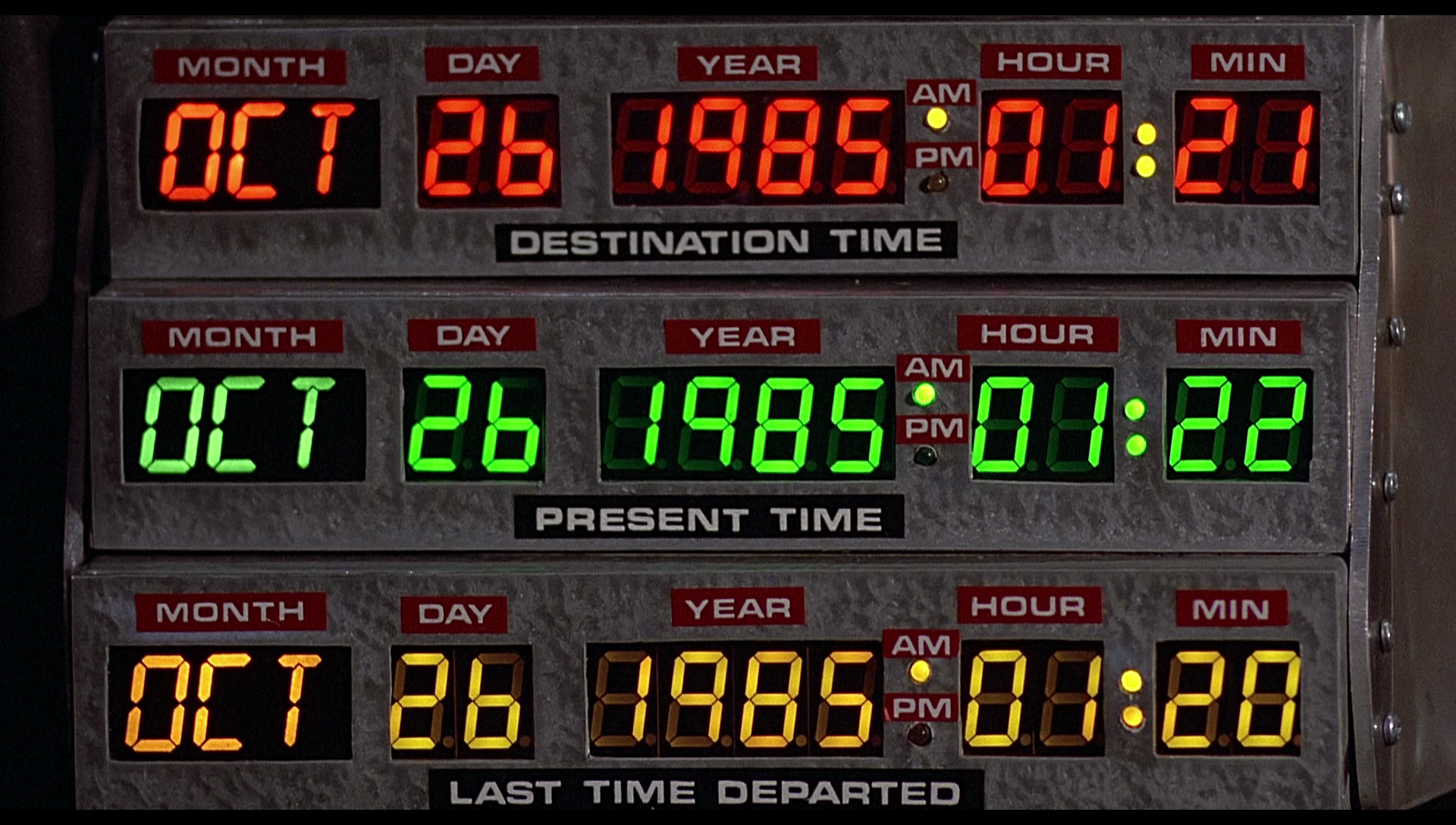
The Original TCD when first seen in Back to the Future
Controlling the LEDs
Today we can fit the control of the LEDs for all 116 LEDs needed in each display, in a single IC. That is, if you don't mind a bit of multiplexing.
Others, like the displays by Dave Madison, and John Monaco have used the Holtek HT16K33 16 x 8 matrix driver in the past for their TCD projects, and I decided to use it here with mine. It's simple to use, and there's already libraries available for it. Furthermore, it uses I2C to communicate, so only 2 wires are needed, which means the displays can be daisy chained. Why make things harder than they need to be? Exactly.
So, to summarize the pros of the HT16K33:
- Less overall components compared to, for example, shift registers = less time & cost to assemble
- Takes up a lot less space on a PCB
- Only 2 wires needed for I2C (plus GND and 5V)
Cons:
- Multiplexing - if a camera were to take a picture with a shutter speed faster than 1/125, then the display may not have all LEDs lit, or may look like it's flickering. You won't be able to see this looking at them in person, because of something called persistence of vision.
- Holtek ICs are not available at US distributors (like Mouser), so they'll have to be ordered directly
Measurements
I began by loading the original TCD in Fusion 360 to measure everything. This process wasn't too hard since you can calibrate an image to a known size. Since we know the original LMB boxes are 8.5 inches wide, that provided a good starting point.
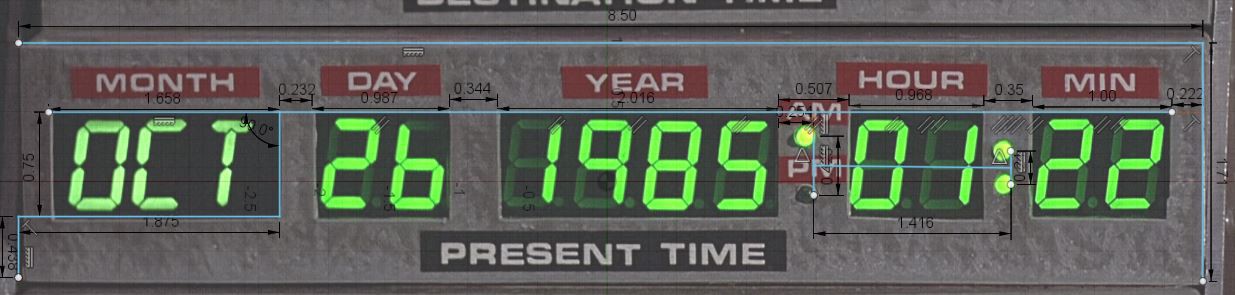
I should mention that, although I ended up using the measurements from the present time display, all 3 displays were slightly different. I bet you couldn't tell just by looking at them!
Laying out the PCB
Using Eagle, I started to lay everything out that would be needed. This included using the custom (sample ordered) segment displays datasheet as a guide.
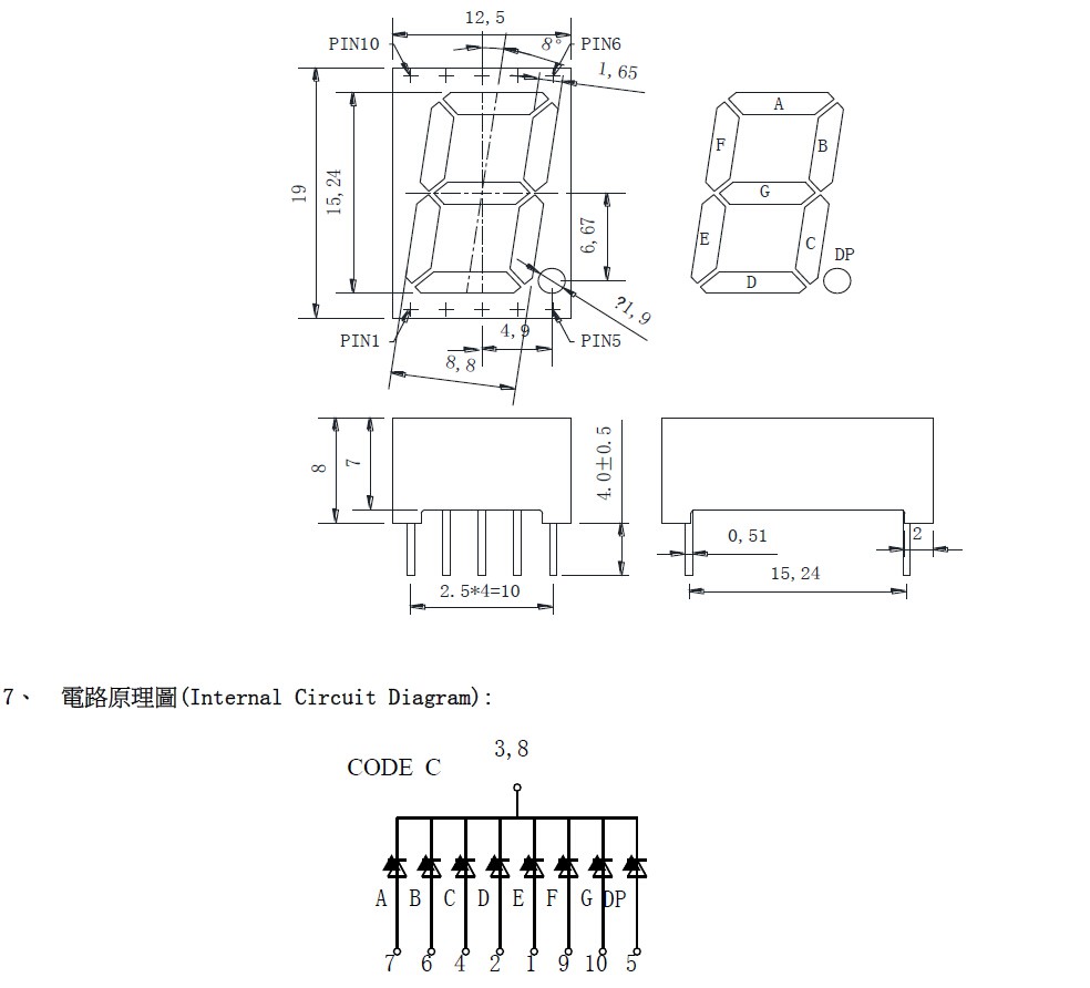
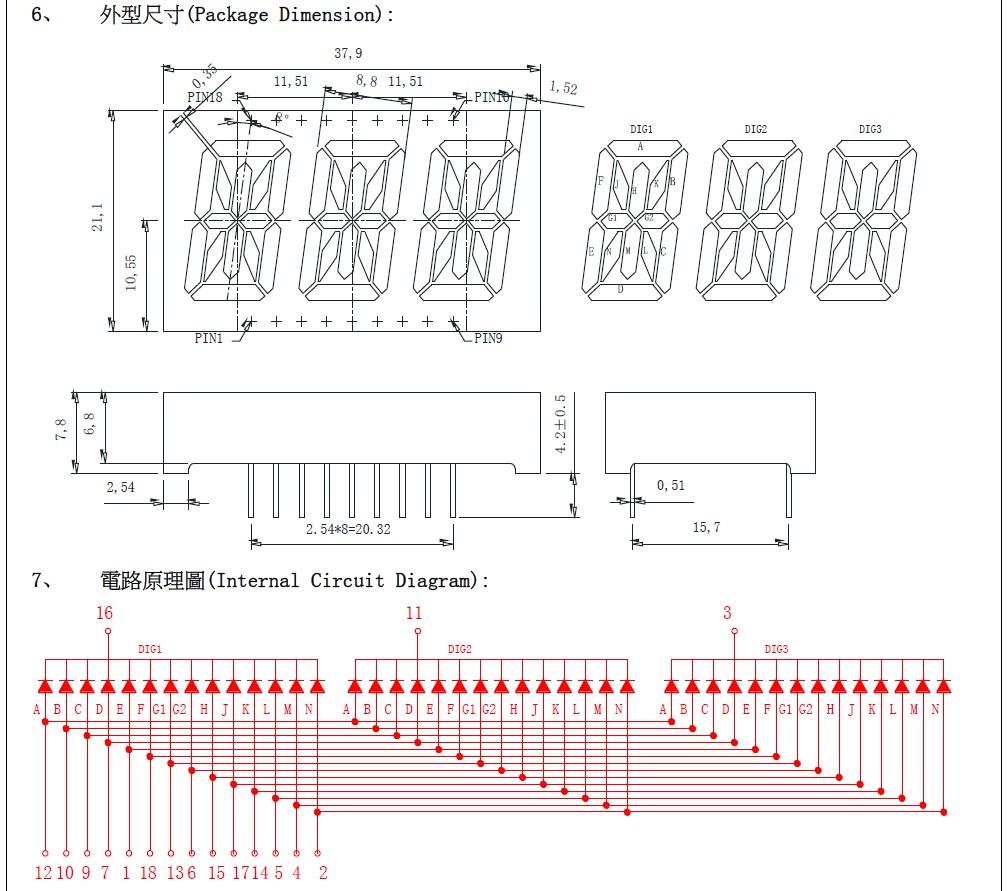
The displays are common cathode, meaning that all LEDs in the displays share a ground, and when a pin is given current, it lights up. In other words, the ground stays the same, while the other pins are what is turned on and off.
The 7 segment displays use pins 3 and 8 as grounds, while the 14 segment has 3 characters natively multiplexed, meaning pins 16, 11, and 3 are the grounds for characters 1, 2, 3 respectively. The positive pins are all hooked together internally. Depending on which ground is activated by the IC determines which character's LEDs are getting lit up.
Note the spacing of the holes for the 14 segment 3 character is taller than the 7 segments. I almost didn't catch this at first. I could reuse footprints for the 7 segments, but the 14 segments had to be custom made, since nothing similar exists anywhere.
Spacing The Segments Correctly in Eagle
This is what it looks like in Eagle with just the measurement layer on:
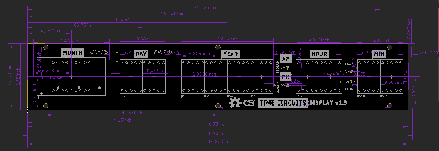
I measured things in mm and in. since most things in Eagle are metric by default, and I had measured the original display in inches.
Final PCB
After some fiddling, a few revisions to make things fit better, and not light up the decimal on some displays, this is what it looks like:
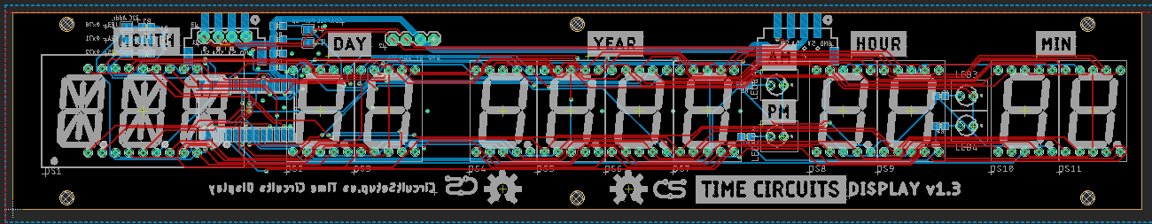
I added 2 footprints on the back of the board for SMD JST 4p plugs, which are the for the power, and I2C. There are 2 so that they can be daisy-chained instead of running 1 set of wires to each display. There are solder jumpers for I2C line pull-ups and address selection for the Holtek HT16K33. The mounting holes are also spaced the same as the LMB Boxes, so they can be mounted to them if wanted.
It's funny to think that the original displays probably had over 100 wires going to each of the 3 displays in some kind of level shifting setup! We have certainly come a long way, and are using less copper in the process!
Discussions
Become a Hackaday.io Member
Create an account to leave a comment. Already have an account? Log In.