Well, it has been some time since the last update.. - but with vacation now there's stuff happening:
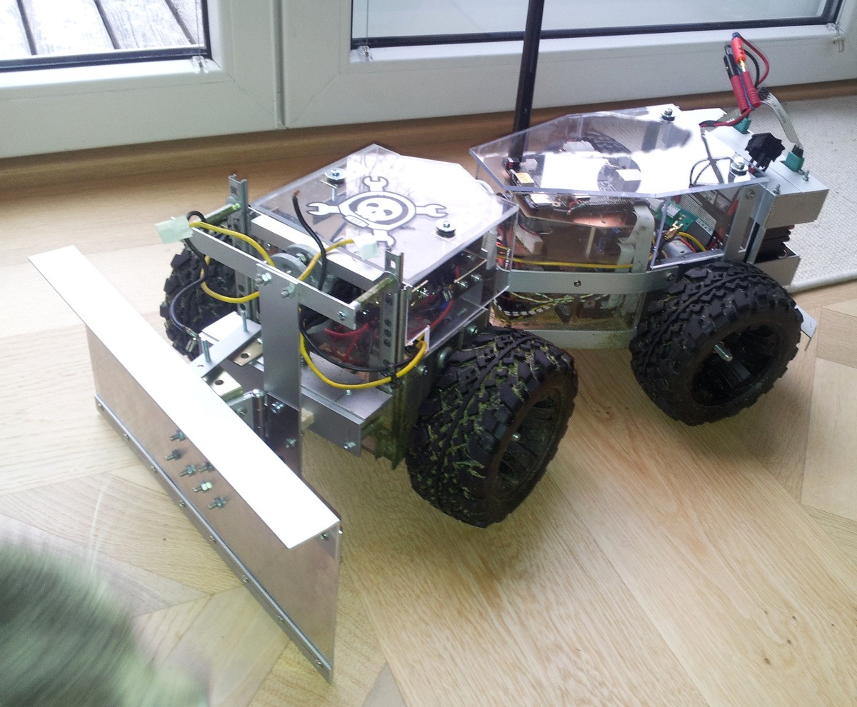
As you can see the casing on the back made some progress and there's a snow shield now!
I assure you it does work reasonably well, but I missed to shot a video and took it apart shortly after. The reason is that now the drive system has to do some heavy work and it revealed some issues:
- The mounting of the wheels to the motors is not sufficient for snow plowing
- The drive system supports two modes: a) regulate torque: measure a torque-ish value from the front wheels, do some calculus and apply it to the back whells b) regulate speed: the speed for all wheels is regulated individually, this isn't ideal for flat surfaces (more motors than there are degrees of freedom -> slightly tearing tires due to inaccuracies) but very nice for snow. Problem: b) doesn't seem to work as nice as it once did, not sure why though. I suspect the BackEMF-speed-measurement to have some trouble
Countermeasures:
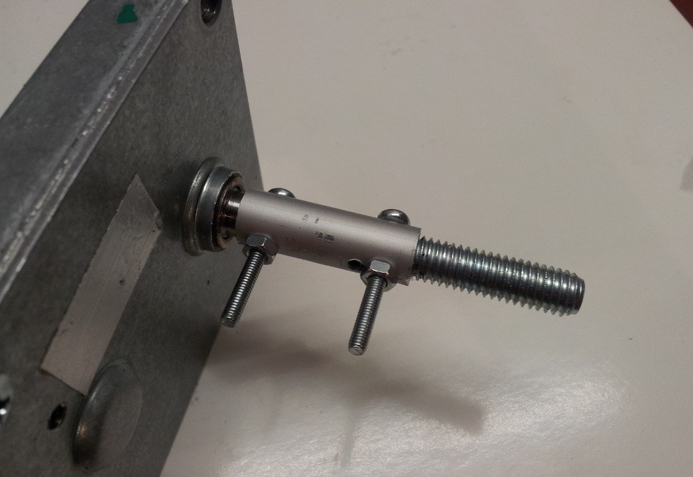
this is the new mounting system for the wheels. Yes, I drilled wrong :-D No problem though.. Thanks to the screws there is no slipping no more and the axis is quite straight as well.
Another problem with the motors was that the connections between gearbox and motor itself were loose in all cases and therefore the whole assembly was rather noisy. To solve that I opened the boxes. Sadly they're not meant to be opened so you have to drill-open them (6-7mm drill, go down ~2mm in each corner). This is what you're greeted with:
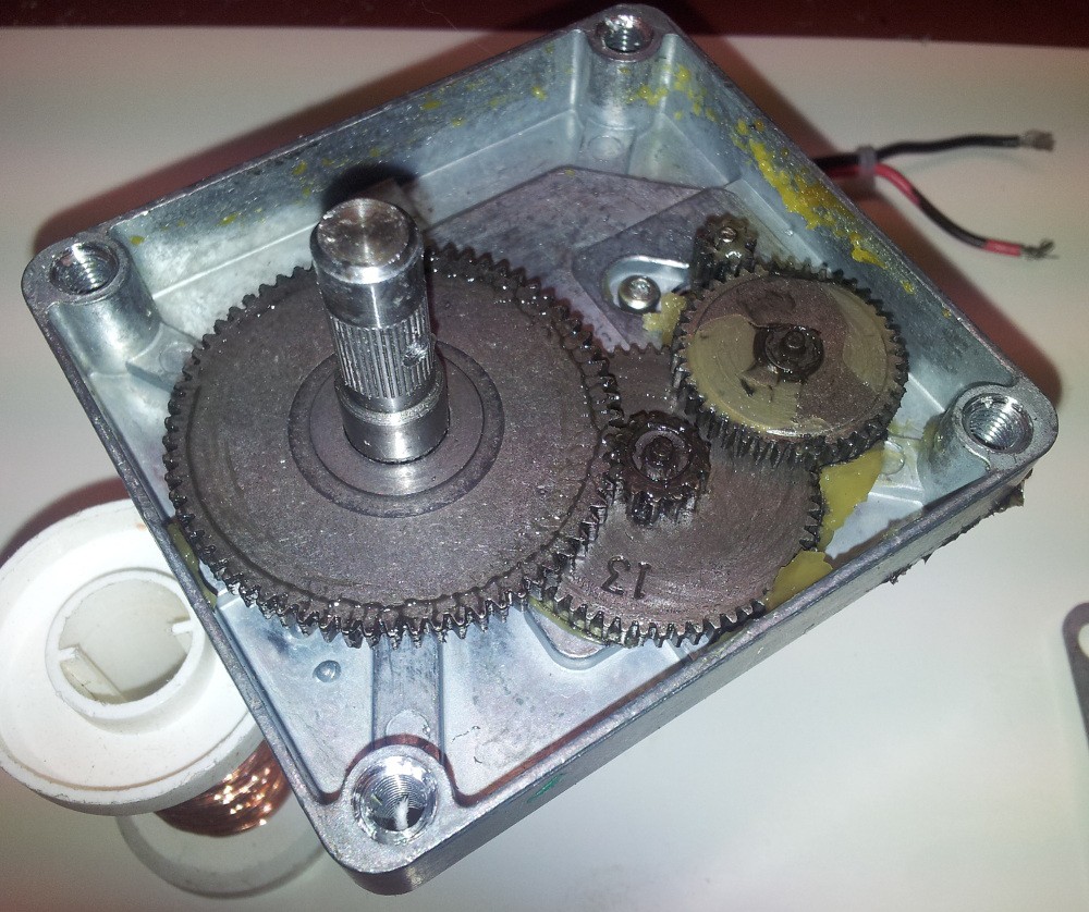
Cleaned of the nasty grease (<- honestly the most work) and disassembled:
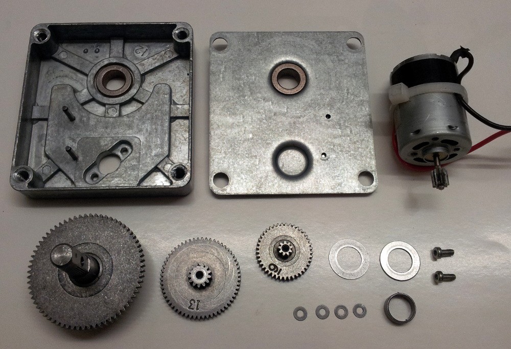
The motors are mounted with (slightly oversized) retainer rings, originally only loctite was used.
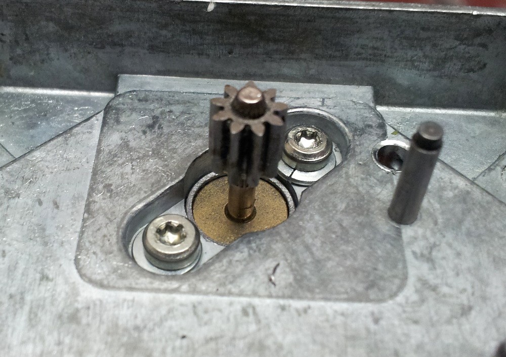
And here's the clue regarding the speed measurement:
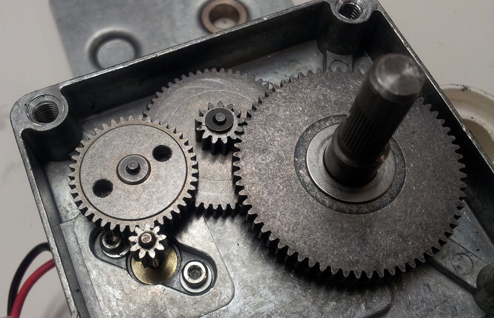
BackEMF is going to be supported by photoelectric sensors, hence the two holes in the gear. Why not replace BackEMF completely? Well, these are the numbers of teeth of all the gears:
- Motor: 9
- Small gear: 9, 41
- Middle gear: 13, 58
- Big gear: 67
Therefore the number degrees per either rising or falling edge from the photoelectric sensor are:
0.5 * 9/58 * 13/67 * 360° = 5.4°
With the 14cm wheels that's a distance of :
0.5 * 9/58 * 13/67 * 2 * Pi * 70mm = 6.6mm
And I'm pretty certain that that's not enough for proper regulation on very low velocity. Now I could drill more holes into the gear, but those are so damn rock solid I ruined all my 3mm HSS-G drill bits with the 4*2 holes already - so no, won't do that..
For the sensors itself I ordered 3mm (like LEDs) phototransistors which get inserted in a 3mm hole on one side of the gear and a 3mm LED on the other.
In case you're interested the the motors: CHM-2435-1 is their model number and they're quite cheap. Got mine for 9€ each on http://www.pollin.de/shop/dt/Nzc1OTg2OTk-/Motoren/DC_Getriebemotoren/Gleichstrom_Getriebemotor_CHM_2435_1.html
And here's another minor thing I added to height adjustment mechanism:
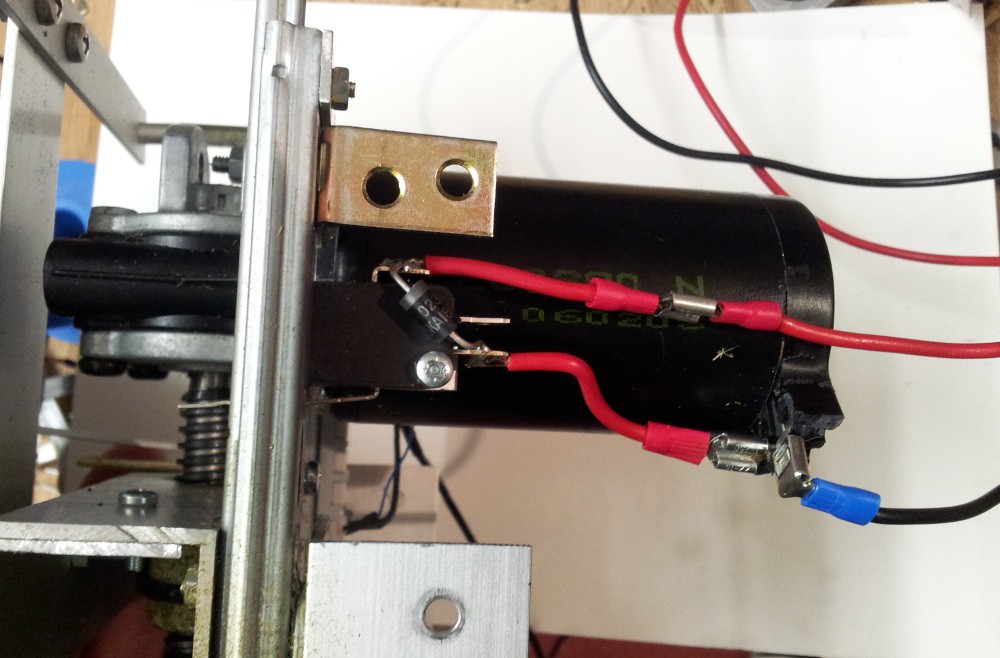
Before in case the connector of the height measurement would have become loose in theory the motor could have teared the assembly apart or made the circuit burst in smoke. Now it gets shut off by a limit switch and a diode allows it to drive down only
 schuhumi
Discussions
Become a Hackaday.io Member
Create an account to leave a comment. Already have an account? Log In.