Was in the office today so had a chance to run up the PA on the bench. Having first carefully set the MOSFET bias so that each was passing something like 25mA (according to instructions here), I could then adjust the drive levels to get a nominal 10W out. Then, sweeping the frequency in bands (4-8, 8-16 and 16-32MHz) the plot below shows how the output looks, including harmonics:
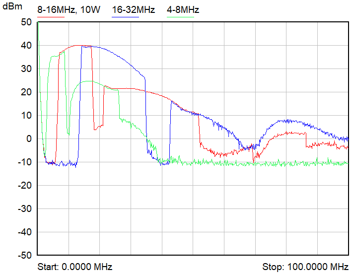
Clearly the output power isn't very flat, but conveniently for me it peaks at about 14MHz (20m band) which is where I was intending to use it most. Third harmonic is the worst offender, at about 23dB down, so a filter is required on the output - no surprises there. Would be good to get the 2nd harmonic from -33dBc down to <-43dBc, so then I'd only need a single LP filter (with corner=28MHz) to cover all the bands from 20m to 10m and still meet "the -43dBc requirement"*. Will see if I can tweak the MOSFET biases to achieve that.
The real shocker was the drive level required: only -27dBm! (at 14MHz). I might just bypass the first stage as I definitely don't need all that gain...
Lastly, this: (14MHz, 12V supply)
| Pout (W) | last stage current (A) | Efficiency (%) |
| 1 | 0.74 | 11 |
| 2 | 1.09 | 15 |
| 5 | 1.75 | 24 |
| 10 | 2.53 | 33 |
I'm hoping a simple moving-coil ammeter on the PA supply will be enough to give me a rough idea of output power.
*interesting that the UK requirements seem to be much more relaxed: "...as free from Unwanted Emissions as the state of technical development for amateur radio apparatus reasonably permits"
Discussions
Become a Hackaday.io Member
Create an account to leave a comment. Already have an account? Log In.