At first an isolated power supply with 12V DC (could be up to 18V, about 60mA) needs to be connected to the barrel jack. The LED should now light up. It's a good idea to check here if the supplies +5 / GND / -5V are correct.
The callibration consists of three steps:
1. CMRR (Common mode rejection ratio): Deactivating the offset calibration by shorting C16 (alternatively: Set RV1 so that Pin2 of RV1 is on GND). Now connect a high voltage source to both HV inputs. I recommend 60V, because this is high enough and save. The negative pole of the source need to be connected to GND. Now measure the voltage difference behind the frontend between the both branches. You can use Pin3 of the diodes D1 and D2. Change RV2 to minimize the voltage. Remove the shorting of C16.
2. DC-offset: Connect both HV-inputs together. Measure the output voltage e.g. at R33 to GND. Change RV1 to minimize the output voltage. By changing the switch between 1:10 / 1:100 attenuation you will see, that the output voltage will change. At the end find a good compromise between both switch positions.
3. Adjust frequency compensation: Similar to passive probes there exists also a frequency compensation C23/C24. Use the 1kHz square wave callibration signal of your oscilloscope and connect it to one HV input. The other HV input must be connected to the oscilloscope GND. Set the probe to 1:10. Now use the corresponding capacitance trimmer to adjust the frequency compensation. You have the correct setting if you have no over- or undershoot.
First test:
The 1kHz rectangular test signal of my Rigol oszi (DS1052E) has only frequency shares up to about 100kHz, so at first I decided to use my 140V source with relais as test source. I compared the signals with a passive Rigol RP2200 (1:10 setting, 150MHz bandwith) and an active differential probe TT-SI9110 (1:100 setting, 100MHz bandwith).
1. DIY probe (CH1) vs RP2200 (CH2), 40V relais pulse: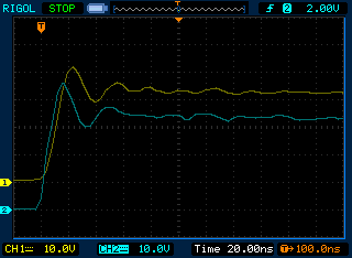
2. DIY probe (CH1) vs TT-9110 (CH2), 140V relais pulse:
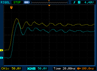
The results look very promising. The probe has less delay, as the Testec probe. The frequency compensetion is not perfect (first peak is lower than with other probes), the trimmer capacitor reached the limit. I have to lower C20/C21 to 27pF. The tested frequencys were in the range up to about 12MHz and the probe has no problem to handle them.
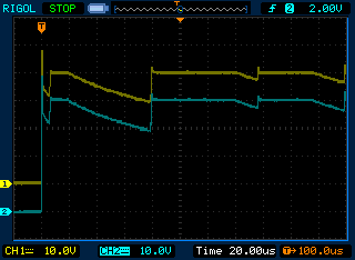
Just for interest, the complete turn on process of the relais in the source at 40V (DIY probe (CH1) vs RP2200 (CH2), 40V relais pulse (20us/div):
Discussions
Become a Hackaday.io Member
Create an account to leave a comment. Already have an account? Log In.