 Eric Hertz
I keep finding uses for it in ways never intended. There's a previous log where I talked about it, some, and drew the schematic...
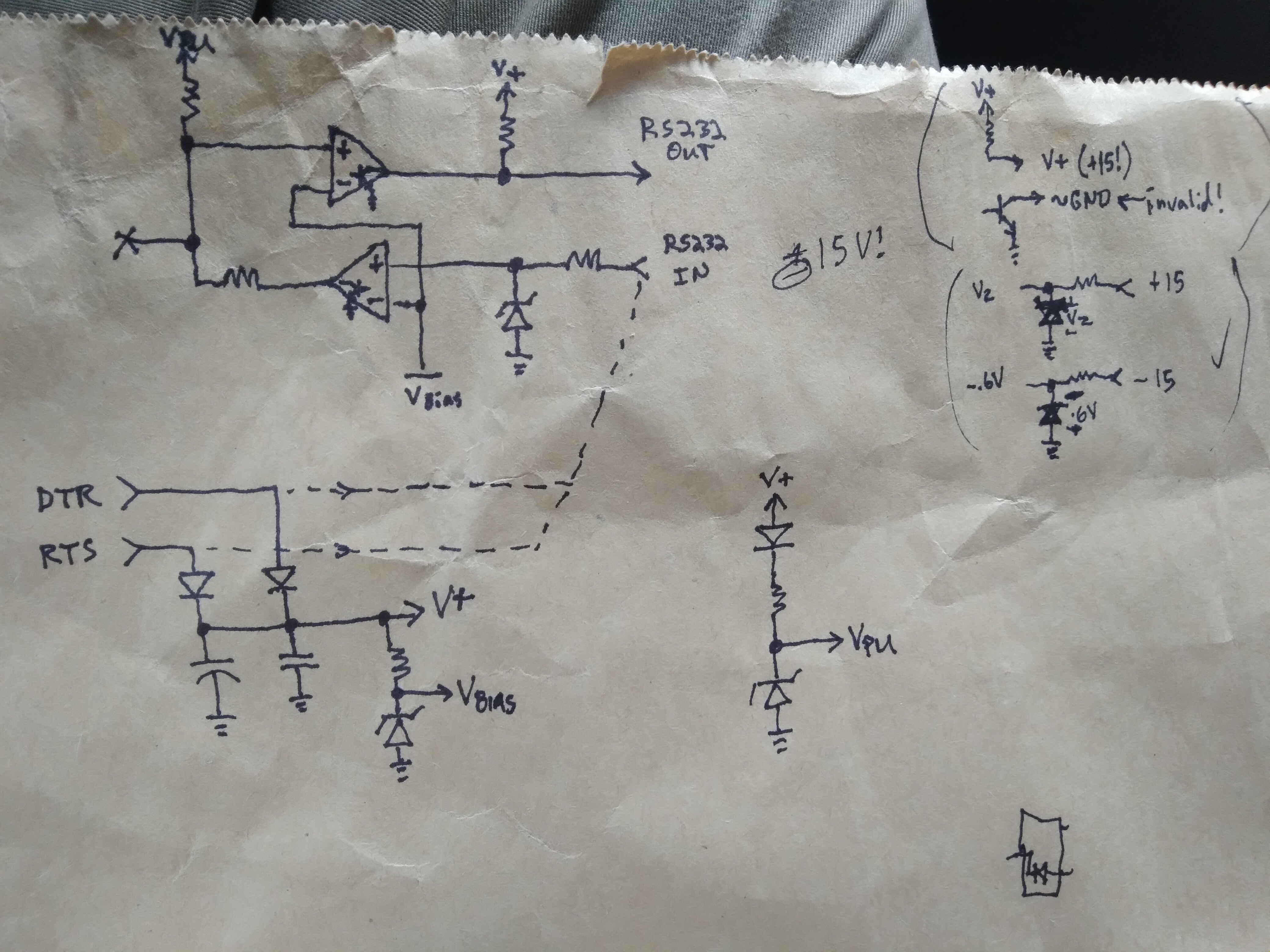
I've used it in /many/ different ways, now... Note that, as I recall, the comparator runs down to 2V and can accept inputs up to 18V or so even when the supply is lower.
The "bias" (more like "threshold") voltage is 1.65V, which is a pretty decent threshold for many different signals, including "today's RS-232", TTL, 3.6V USB-Serial, and even 12V signals in a car...
My USB-3.6V serial converter has a 3.3V zener at its Rx input, so I considered just connecting the calculator's link port to Tx and Rx, directly. BUT, actually, the calculator could feed up to 6V back into the /Tx/ line, which I don't think is a good idea. So, I just threw the "blacklink" between, for good measure. Its DB-9-side input is not pulled-up, so no feeding 6V into the 3.6V output on my USB-Serial Converter. The pull-up at the graphlink's output is pulled to the voltage of the DB-9-side's largest voltage, which is 3.6V from Tx, so the zener's really not necessary.
Anyhow, I'm not really wording well right now, but here's the current use-case, very different:
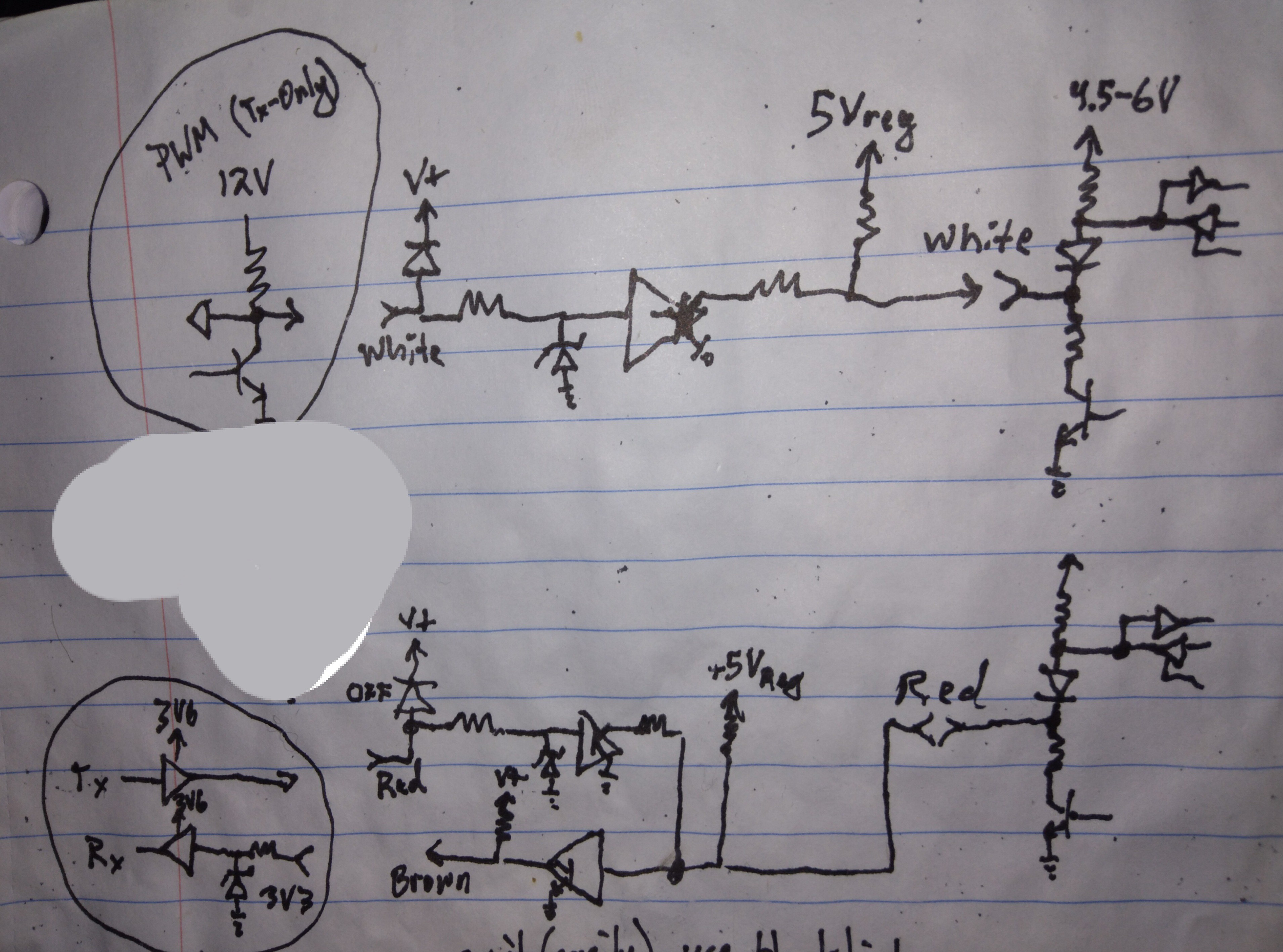
PWM is (I think) open-collector to ground, pulled up to 12V. I need the calc (circuits on the right) to read that, not write. The graphlink circuitry inbetween not only converts that to TI-link's levels, but also supplies 12V to the graphlink's circuitry through the diode at the input. Since it does this, I'll probably wire up 12V directly to the graphlink's power capacitor, just in case that pull-up and the heavy data flow allows that voltage to sag.
But now there's 12V in the graphlink... what about connecting to my 3.6V-UART signals? (BTW, did you notice the blacklink /also/ adapts my 1-wire bidirectional UART (on the calculator's red wire) to Tx and Rx for my 3.6V UART? Handy!)
Tx is simple-enough. There's no pull-up on the DB-9-side inputs. Threshold voltage is 1.6V. Great!
Rx, well, I already have the 3.3V zener at its input, and since the blacklink doesn't /drive/ during high outputs, instead pulling up with a resistor (yes to 12V, weakly) the zener shouldn't have to sink much current to keep a high input at a 3.6V-logic-safe level.
That's pretty much it! Now my calculator can interface its bitbanged 1-Wire bidir UART with a 3.6V 2-wire Tx/Rx UART AND read a 12V "clock" signal from my car. And all i had to do was reroute a few pins from the graphlink's DB-9.
(OK, and make sure there's a zener on Rx, and I soldered in some wires to the blacklink's power capacitor a while back).
....
Trying to parse this from TI's datasheet of the LM339 comparator used in the blacklink:
"The upper end of the common-mode voltage range is VCC+ – 1.5 V; however, one input can exceed VCC, and the comparator will provide a proper output state as long as the other input remains in the common-mode range. Either or both inputs can go to 30 V without damage."
...
This note seems in conflict with other specifications, especially "Recommended". OTOH, without taking this note into account, the blacklink's circuit is not within the Recommended specs. Because: It draws its power /from/ the input... through a diode. So the input voltage might be say 0.6V higher than VCC. The above quote seems to be saying that's OK. The recommended parameters don't.
The alternative is to consider the second diode at the comparators' inputs. This is reverse-biased to ground. Initial guess was to protect the comparator input from /negative/ input voltages, which would likely be present on an RS-232 signal. Bringing a negative input to, say, -0.6V. This is out of range, too. -0.3 is the LM339's spec... So, maybe it's shotkey. But, then, unless it's zener, the input still exceeds VCC. Meaning the above note is important to its design.
Currently, this is especially relevant to my hacked-use of the blacklink.
Usually its inputs are connected to RS-232 signals which actually have high/low /drivers/ rather than open-collectors with a pull-up resistor. So, my 12V signal will try to power the circuit, through I think a 250K resistor... Charging this thing's capacitors will probably hold that signal low or indeterminate for some time. Not a great idea. I guess that's the answer. I really should power this thing externally.
The other input is connected to my 3.6V driven signal, which mostly sits idling high... so the 339 would be reliably powered to 3.6V minus a diode drop. And, I think, the above note says the circuit itself should be fine with that, even with a 12V signal at the other input. But, since the other input also has that diode to VCC, the 12V signal will try to /increase/ VCC to close to 12V, at the expense of dragging that input signal down with it... Which might interfere with whatever communication goes on there (even though I don't intend on reading it).
So, it seems, I need to actually power the blacklink's VCC with 12V. Again, no biggy, electrically... Its design won't put 12V on my 3.6V signals, which was the original concern. (It wil pull up to 5V, but my input has a zener regulator). So, I guess it's kinda funny that the concern isn't about overdriving low-voltage inputs, neither at my 3.6V circuitry nor at the possibly under-voltaged comparators (which apparently could handle it, even if it was powered by 3.6V?!), but instead the concern is overloading a high-voltage output.
Yep. I should power it with 12V.
Good thing I soldered leads to its capacitors!
...
NO! I've gone over this before, sheesh... Am mixing up ghe Link-side with the DB-9 side of the graphlink. The DB-9 side outputs are pulled up to VCC (~12V, in this case). That'd be fed into my 3.6V input, if not for the zener and resistor at its input. I think it should be OK, but it may sink a bit of current. I stupidly put that resistor in heatshrink, so dunno its value. my plan, originally, was interfacing it with 5V logic, so 220-2.2k ohms mighta been the choice. Probably lower than higher since I probably tried to account for high baudrates. But, the pull-up in the blacklink should be probably 10k or more to match.... dagnabbit, NO! Wrong side again. DB-9 side. Still, OK... RS-232 can be +-15ish V... so that pull-up must be high-ish valued, otherwise it'd drop mAs whenever the output was low... So, whatever value it *is* should drop even less current when regulated to 3.3V rather than tied to ground... O.K. whew.
Discussions
Become a Hackaday.io Member
Create an account to leave a comment. Already have an account? Log In.