 Eric Hertz
whelp... I managed to speed up the sampling rate dramatically...
My signal is /supposed/ to toggle (or not) at 8us intervals...
My original sampling code took 39T-States per sample, or at 6MHz 6.5us/sample... IF I understand the z80 right...
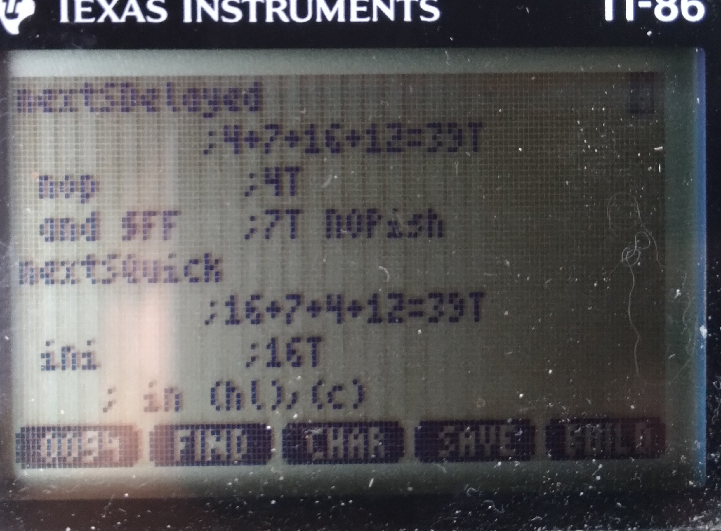
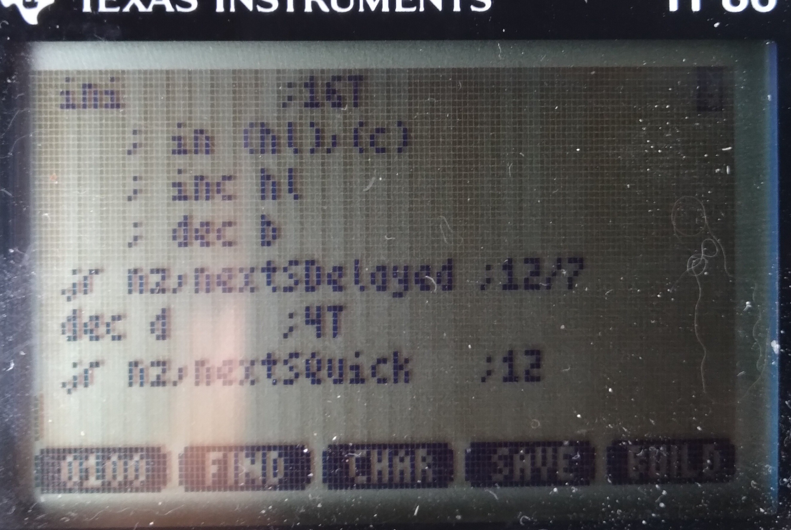
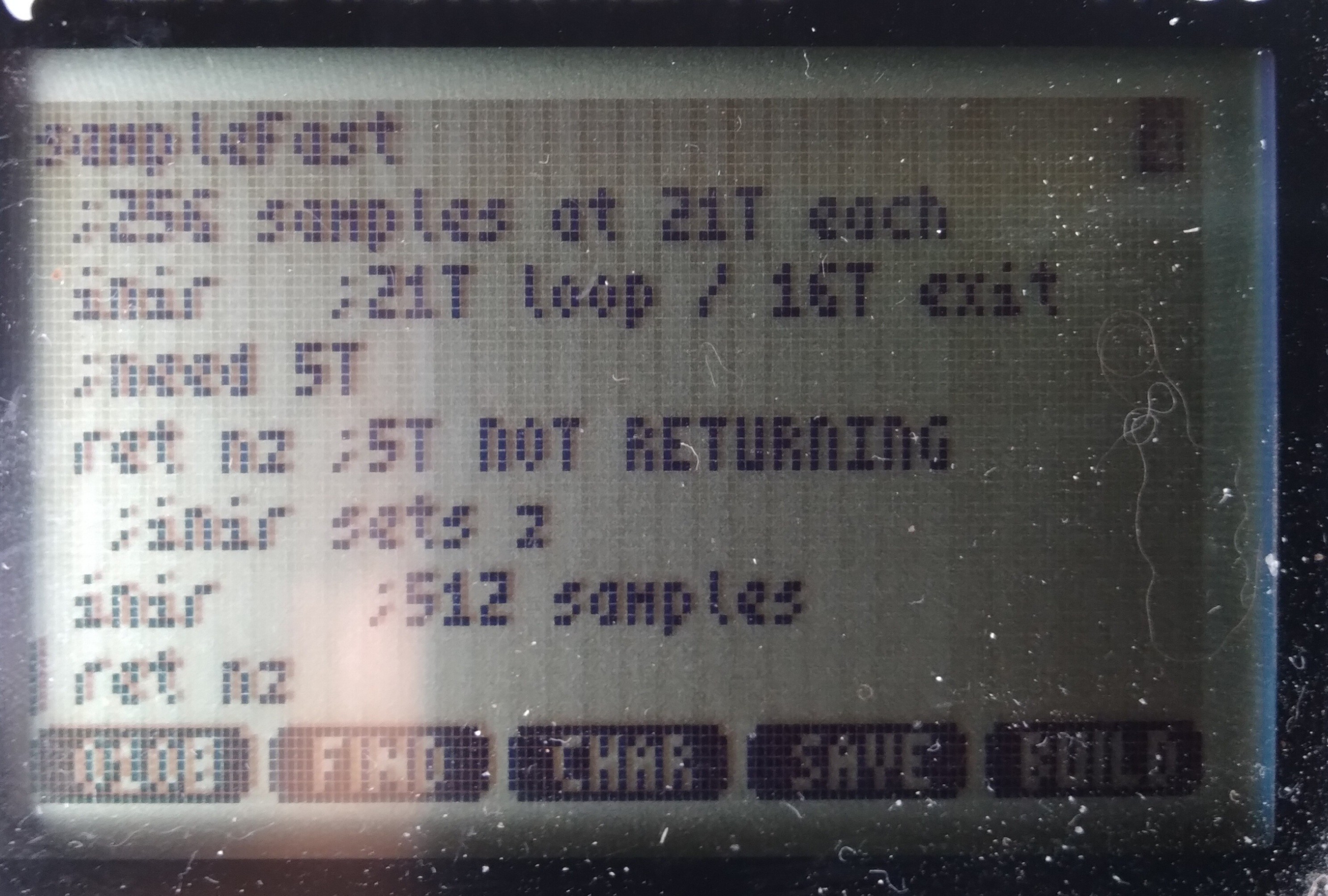
The new code doesn't use a loop. INIR takes 21T states for each of 256 samples until the last one where it takes 5 fewer, since it doesn't repeat/loop itself.
So, presumably (I have Very Little to go on, here) if I insert a 5 T-State "NOP" between calls to INIR, then samples would be perfectly spaced in time, even crossing from sample 256 to sample 257. Thus each sample now takes 21 T-States, or 3.5us (at 6MHz). Right?
Now, at 3.5us/sample and 8us signals, each high or low should be /at least/ 2 samples, right? I mean, even if it's as they say and the TI-86's clock speed decreases with the batteries, still hard to imagine it'd slow too dramatically... 2+ samples per high/low still seems pretty reasonable... right? And, /surely/ the clock rate doesn't vary dramatically between cycles, right?
But... Apparently....
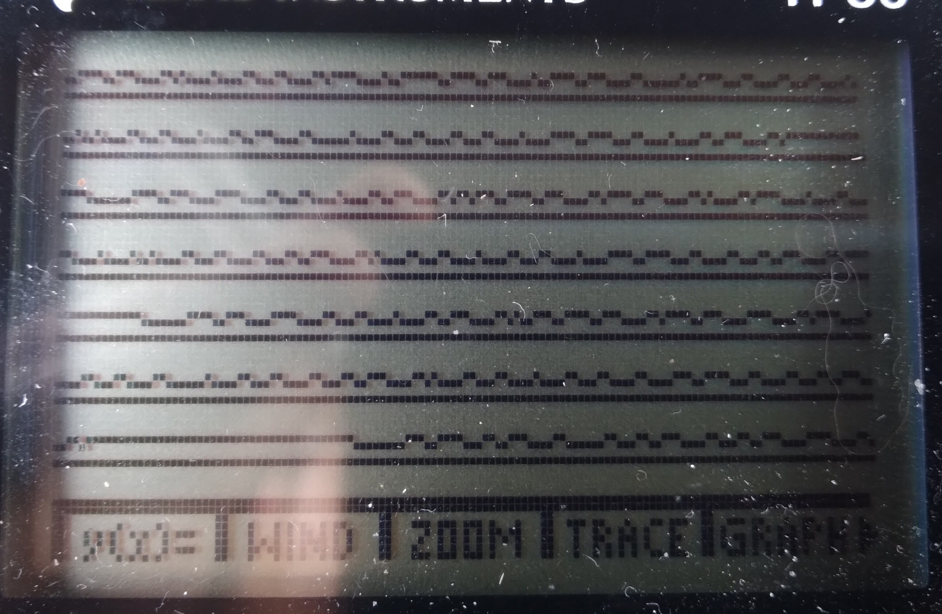
There are still /many/ single-sample highs and lows, some even back-to-back!
...
I'm at a bit of a loss... theories abound, but testing them all would be quite an undertaking. Especially since documentation on this protocol is /sparse/.
The other factor is that this may not really serve my end-goal. Theory there, allegedly, goes that since this particular signal bus is always chattering, rather than only responding to requests from the external device (i.e. my calculator), there must be another signal bus for the latter purpose.
Now, there /is/ wiring for that... but, as I said, documentation has been sparse, and since it'd only speak when spoken-to, I have to figure out /how/ to speak to it in the first place! And, of course, /presume/ that whatever I come up with actually "sounds" like what I think it should to the other device. Did I mention that this second bus uses a different protocol entirely?
So, there's that...
Now, from what little I understand of /this/ bus/protocol (in the screenshot), I shouldn't be seeing what I'm seeing. Which suggests /my/ "ears" aren't even hearing correctly what's being "spoken." So, if /that's/ the case, then surely /speaking/ yet /another/ language, with /no/ real-world examples to learn from, would be quite difficult, nevermind, again, expecting what I speak to actually /sound/ like I intended. Hah!
In TI-86 terms: I wonder whether what I'm seeing is the result of many things, e.g. a lack of documentation regarding special cases (i.e. the "host" is interrupting a talking device, or two devices try to talk simultaneously, and they're negotiating, etc.) Or, maybe, there are interrupts going on in the Z80 despite my having disabled them, slowing two samples. Or maybe there are wait-states /internal/ to the z80-VLSI when accessing port7.
Or, here's a weird one, because I came across it for different reasons entirely, WabbitEmu's TI-86 source code https://github.com/sputt/wabbitemu/blob/master/hardware/86hw.c has a "port 10" which, if I understand correctly, is used to transfer the LCD framebuffer to the emulator's display memory... could it be that /that/ is how the real implementation works? A bunch of OUTIRs to the display, much like my INIRs...? I did some grepping of the firmware for other in/out functions, rather than the 'in a, (10)' or 'out (10), a' instructions which are easy to grep... nothing stuck out. And, besides, the LCD keeps refreshing even when interrupts are disabled... So, that'd require an NMI, no? And, surely, that'd've been well documented by now... its effects would be tremendous on all those game devs! So, is "port 10" (and a similar port 11!) a hack for emulation purposes, or a real thing not documented in any of the usual sources? (Note that port10, as i recall, is an actual thing on e.g. the TI-83, but that uses a different Z80-VLSI and a different/external display controller... so may be an emulation-hack)
I dunno, weird.
So, I guess the question is whether I'm reliably sampling at a steady sample-rate, or whether /something/ is capable of interfering with that... wait-states internal to the VLSI (why?), internal NMI (for the LCD?), really unstable R/C CPU clock? Other ideas?
Note, those "glitches" aren't aligned with samples 256-257, though my fake 5T NOP may still be misaligning samples, as well.
...
So, then there are other considerations, e.g. the rise/fall-times of the various intermediate circuits (the graphlink I'm using as a level-shifter, etc.) could also have an effect; though, I'd think that'd be visible as consistently longer highs and shorter lows (or vice-versa)... so single-sample glitches, especially back-to-back seem outside that realm... But, maybe not, since I'm powering the thing from 5V, which isn't enough to provide a pull-up on the graphlink side of the TI-Link... hmmm...
There are /so many/ possibilities. Could be any or even a combination of all... some may be specific to this bus which apparently isn't the one I need, some may be indicated by what I'm seeing on this bus, and necessary to figure-out, from it, since I'd be going into the other bus "blind"... and some (e.g. NMI) might even be flat-out show-stoppers. Heh.
...
DMA? Heh. That'd be the "logical" choice for LCD refresh... maybe I got too hyped-up on my idea they might've used DRAM-Refresh cycles for that purpose. I think there's a way to disable the LCD, and likely its loading/DMA via a couple port bits. From the docs I've seen, it's pretty unclear /how/ they function, as opposed to /that/ they seem to...
For shitz-n-giggles: 1024 bytes on the LCD, at 6MHz, 170us to refresh (presuming 1 clock cycle is enough per byte, which might be a big presumption)... at 200Hz, that's 34ms per every second spent refreshing the screen! 1/30th of the processing time?!
Seriously, they couldn't've, could they?! 1/10th, 10% of the CPU cycles, if each byte takes 3 clock cycles...
That, ehhem, could be a large part of why most of the later calcs switched to a different z80 VLSI and an external display controller... heh.
OK... next time I've run a full backup I'll try disabling the display again :/ last time I tried, "Mem Cleared"
Am kinda saddened by the thought they might've not been more clever... DMA when you've got an otherwise unused bus cycle already dedicated to sequential background memory accesses?! Am I to presume there's actually a /RFRSH pin on the T6A43?! They might've actually still planned to use DRAM? (Which pin is it? There aren't many left!). And, again, even still, (Note To Self for my possible real z80 compy-design: use DRAM, just to prove it) those refresh addresses being sequential, and only the low 7 address bits being used for DRAM, they /could've/ used that same system for BOTH DRAM refresh /and/ LCD refresh, simultaneously. GAH!
...
IF they used DMA to refresh the LCD, all 1024 bytes at once, would it've interfered with my UART bitbanging?
171us is 5.8KHz... my glitch-free 512KB (5.12 million bits, including start/stop) transfer at 4800baud (208us/bit) /might/'ve been feasible, with a forgiving receiving UART... 9600baud, probably not. It was just chance the settings were still at 4800 when I'd gotten perfect data at 19200 earlier... what was the reason I switched it? Oh yeah, /ultimately/ (DAYS of debugging later) it turned out my 'bash' script had a fundamental[ly weird] flaw that looked like lost data. Heh.
So, it seems I mighta lucked-out the display refreshes didn't corrupt my data transfers... if this whole DMA thing is the case.
Or, it's also plausible it only DMA's a row at a time, which would only be a 2.6-8us delay, which might not interfere with even 19200baud, plausibly even 57600... hmmm...
.....
4.123MHz I measured. I coulda sworn I read 6MHz.
Now, this was a pretty rough test... disable interrupts, push Enter, count T-Cycles, Push Enter again. But, I did it 3 times at 10sec, twice at 20, and once at 60sec. All seem about 4.1MHz.
...
I have not yet tried disabling screen refreshes... but, 30%!? I guess it's plausible, when combined with low-battery-slowdown.
But, the weird thing is, most of those samples look just about right! Only a few seem gnarly. And this across the two expected-sample-rates of 6.5us and 3.5us.
...
I need to try disabling the screen refreshes, but last I tried I wound-up clearing the memory. So, first a backup... haven't had the opportunity.
...
I can't think of anything else in this system that might use something like DMA... but, having previously thought they wouldn't've for the screen, now I'm left wondering what other surprises may be in store.
...
This speed test came about because I started looking into the other bus's protocol... It's simply a UART, and at a much slower baud... So, actually, it should be far easier to work with. But, 10% timing error is a full bit, so I need to have a better idea of this machine's actual clock speed.
Unlike the UARtoST (hah, autocorrect reminded me I'd added that S), there's no source here to synchronize to.
...is what I'd been thinking.
BUT, check this: the /other/ bus transmits pretty regularly. So, maybe I could watch /that/ bus, just for the sake of timing.
Might be a bit difficult, at 8us toggling... I don't think I can measure the number of T-States between a rising edge and falling edge. Nor could I even, say, count ten rising edges, in realtime...
BUT, I already have the "logic Analyzer"... so, I could take a few hundred samples, each at a known interval of T-states, then process them /afterwards/ to /calculate/ the number of T-States, say, per second.
It may be the calculator's clock frequency can vary dramatically with temperature and battery level, but I doubt it varies anywhere near 10% in a couple seconds!
So, now, I've got a means to determine how many T-states per UART bit. That is... /if/ I can figure out what's going on with those weird samples/bit-durations.
...
The /original/ idea was to literally do it by-hand, heh. Start the program, press enter, wait one minute, press enter again, calculate clock frequency, /now/ begin the serial stuff. I think that'd work just fine. One second off on both sides is only a 3% error. Pretty sure most UARTs can handle that. And, who knows, I may go that route initially, anyhow. Though, if this thing turns into a thing, it'd probably be more prone to frequency-drift over time, and it'd be good to compensate for that. And, I don't even have to understand the other protocol to make it serve this purpose. Groovy!
...
I can't quite wrap my head around the fact I'm writing all this code in a language (and system!) that's /so/ specific. Usually I like to keep my work generalized so I can use pieces again in later projects. Heh! Conceptually, sure, reuse is possible. But all that painstakingly thumb-entered code! Sheesh! Heck, I had to write a routine just to print out a value in hex! In Assembly! For a CISC processor! For TI-OS! What's my world come to?! Heck, they're not even regular-ol' text files! I gotta use a converter or a special program just to /see/ my hard work on a regular-ol computer!
But, fact is, some of the things I'm perty durn proud of are nearly as, if not far more, specific... #sdramThing4.5 "Logic Analyzer" comes to mind. The challenge of making the most of what's available, I guess... Making it do things that some might consider impossible, given the resources, and expectations that needn't be so rigid. Many of the concepts can be reused... in sdramThing4.5's case, many were, from other projects, in its creation, while many more were created with its growth. I really like, for instance, how the cursors were implemented... The screen AND sample timings are loaded into, essentially, a framebuffer. But, since the lvds signals sent to the screen are divided into three separate channels, and since the channel containing screen timings /also/ contains the upper blue bits, I repurposed the timing framebuffer to /also/ include the blue cursors. A second separate "framebuffer" contains the samples, which, of course, gets rewritten during sampling... and then, at the lowest level, the framebuffer/sampling/memory-addressing/timing is all handled by the memory itself, a concept that later went into #sdramThingZero - 133MS/s 32-bit Logic Analyzer ... I dunno, I kinda dig it. Prety sure no one's done similar, and yet, the memory has the necessary features to do so many things we usually develop yet another system to do for it. Heh!
...
So, back to the TI-86/z80 endeavors, here... well, I guess I never realized how blessed I was always having a crystal-oscillator or /surprisingly/ accurate (laser-trimmed!) R/C clock for my projects, or the seemingly universal availability of a dedicated timer/counter for precise timing of things like bitbanging a UART.
Nevermind single-cycle instructions! Counting T-states is crazy... NOP is 4T, but a conditional jump is 7 if the condition is false or 12 if the condition is true... so if you want the same number of clock cycles in both branches you can't just use a NOP, you'd have 11T false-condition, 12T true-condition! So, then, looking through /all/ the instructions to try to find one which can be configured to have no effect, but will eat 5T... heh! OK, what about "add a,0"? Nope... "and a, $ff"? Nope... I've dug up a few such oddities like that that could be useful for various-length "NOPs". The least-expected, thus far, being "conditional return" wherein you know the condition will never be true, so it doesn't /actually/ return, despite being the purpose of that instruction. Heh! So, now, looking at a disassembly, here's some weird program that has a dozen [conditional] returns... so then yah start hunting for the condition that would cause it to seemingly end early without going through the usual function-exit stuff of setting a return-value and popping the used registers... And eventually you find "hey wait a minit! Those conditions are /never/ true! What on earth is he doing?! Maybe this is a lookup table?" Heh. What a weird endeavor.
"A=A or A"
"A=A+0"
"A=A and 0xff"
Oh, then there's things that do things, but not like you'd expect them to be done...
"A=0" vs "A=A-A"
Or my favorite, in the "it's friggin ridiculous" sence...
"SCF" means "Set Carry Flag"... so, surely, CCF means "Clear Carry Flag," right? Nah, CCF means /toggle/ carry flag. So, to do it, first SCF then CCF... /or/... shoot, I can't recall the trick... oh, there are a ton of instructions that only /clear/ the carry flag. Dunno why they even bother affecting it, frankly. AND, OR, many others... there is nothing /to/ carry in these operations, so wouldn't it've made sense to just leave the carry flag alone? But, /since/ they do, those instructions are often used not for their intended purpose, but instead /to/ clear the carry flag! HAH!
At this point it starts seeming that understanding a disassembly would be darn near impossible. Maybe that's why they call it "code".
Here's another weird one, conditional jumping... do it relative and it takes /more/ T-states than an absolute conditional jump. But, wait, it's got fewer bytes to load! But, instead, it takes some clock cycles to do an addition. Surely an addition doesn't take as much time as loading two bytes from the bus... oh yes it does. Heh! OK, then what's the benefit of a relative jump over an absolute? It uses one less byte. And, no, that does /not/ imply faster. CISC FTW!!!
Oh, wait... that and it's relocatable. Right... oh, and, if the condition is false then it takes fewer T-states... OK, now it's starting to make sense... BUT, /relocatable/... hmmm... that seems pretty important in most z80-based systems (not so much in TI-OS) which load programs from floppy disks, or from ROM into faster RAM, right? So, then, wouldn't yah think, yahknow, intuitively, that they'd've gone to great lengths to make the relative jump /faster/?
Frankly, it's totally unintuitive, probably mostly based on history... relocatable code probably wasn't /really/ much of a thought, when systems like those were mostly designed to run one program at a time. So, then, relative-jump really basically only existed to save a byte on the floppy disk (or audio cassette!) and RAM, and had the nice side-effect of being faster if the condition is false.
Frankly, it almost seems like they just threw a bunch of random features together... make it random enough, make enough of them, make sure they cover a few basic necessities, and it'll eventually be turing-complete. Might be "quite a hack" to figure out how to do some simple things, like set A=0 or clear the carry flag, but it /can/ be done. Now, we've got /these/ to work with, what else can be made of them? I know, let's microcode huge loops and various /really/-specific features, and put them in the unused op-codes, rather,'n, say, make a 1-byte, 2T-State opcode to set A=0 or clear the carry flag, or increase the calculation-speed of adding a relative offset to the program counter! Heh! Gotta remember, Back then human memories were /much/ larger than computer memories.
Interesting, anyhow. Not unlike the crazy workarounds I did for sdramThing4.5... working with whatcha got, I guess. Suppose it could be a metaphor for something bigger.
...
Wait a minit... look again at the skinny-glitches...
Is it just me, or do they seem somewhat-evenly-spaced? Maybe about 22 samples apart... hmmm... single-line LCD DMA? Seems too fast... 22 samples, 21T/S, a 16byte row-DMA every 400T?! 64 of them per refresh... 25600T/refresh... at 6MHz... 4.3ms/refresh... 5ms is 200refreshes/sec... holy moly, I think we might've confirmed it.
...
We're getting into the realm (actually are probably way within the realm) of "is this really necessary?"
But, here's some more analysis:

so, these numbers may /seem/ somewhat random, but there are a couple factors to consider: i counted samples *between* (not including) glitches. I /counted/ pixels (which of course, may be off by one or two). Glitches won't /always/ be visible, e.g. if they just happened to occur surrounded by two lows. Also consider: if they are the result of, say, DMA, then those requests could happen anywhere during the sample loop, or even during the retrieval or execution of an instruction. Then, it stands to reason that, say, if it occurred during the sample instruction it may delay the sample, but if it happens /after/ then it may delay the loop, etc.
Ok, so considering an average of two samples of error, it's looking very much like 8*x samples/glitch: 8, 16, 24, 32...
Is it possible the screen DMA only loads one byte per request? Why not... or two, or four... sixteen makes a row.
Earlier napkin math was based on 22S/glitch, say it was 24... the math seemed to work out, but 24/8=3, i kinda doubt the lcd loads 16/3 5.3bytes/DMA-request. Maybe it's 4*x samples per glitch? Or 6*x? Hmmm.... 6, 12, 18, 24, 30, 36...
Anyhow, i think there's a pattern, and I'm pretty sure, now, it must be a periodic DMA request (or NMI, maybe) periodically delaying the samples. I'm guessing it must be the LCD driver, and I'm thinking it does really short DMA transactions, even shorter than the entire row of 16 bytes. I'd've thought the DMA request/allow process would have too much overhead to justify a lot of tiny bursts, but maybe not. A smart-enough DMA system might actually be able to inject its requests while the CPU is processing a previously-retrieved instruction, kinda how the 8087 FPU works with the 8088 by watching the instructions being fetched (crazy!)?
Anyhow. The simple test is to disable the screen... but, again, just 'cause the samples may look right thereafter doesn't necessarily mean there aren't other such things going on... so this is all based on quite a bit of presumption.
My baud-rate-generator /probably/ would be close-enough, with these seemingly tiny bursts interrupting somewhat randomly, since calculating the timing would be based on the average /including/ these interruptions which I now presume are far shorter than a bit-duration.
...
Many hours scouring various sources regarding how to turn off the LCD... Frankly, even the /same/ documents contradict themselves.
So, I did my best-guess and I think it does the job... no crashes, at least!
Oddly, I ran a 60 second T-State count both with the LCD running normally, and with it seemingly powered-down, and the difference is minor, 4.446M Tcounts with the LCD off, 4.113M Tcounts with it on.
At 200Hz refresh, 1024Bytes on the display, that's 204,800B/sec
.... hey, wait a friggin' minute.
The difference is in... oh yeah, my MTcounts are per second, not the total for the minute. Ok.
Right, so I ran the tests twice each, and it seems about right, about 313,000 extra Tcounts per second when the display's disabled.
So, very much on-par IF one byte gets transferred each bus cycle while it's doing DMA. Which, I guess, doesn't seem unreasonable. The consideration *might* have been that this was designed long enough ago that maybe they would've been a bit ahead of the curve relying on memories that fast... and/or that fast of a DMA controller, on the same die as a CPU which uses two T-States per memory access. But... why not, eh? So, a little bit of overhead, maybe the first cycle when the CPU releases the bus is too short to rely on... maybe the DMA controller can't release the bus in time for the last byte to be read and the CPU to fetch the next instruction-byte, etc. in adjacent cycles. So, say it adds two cycles to each transaction, 4 bytes might be accessed at a time, making for 6 cycles, then 204->313 is dang-near spot-on... right? K-then... 6 T-states per DMA at 4.446MHz makes for 1.35us... which would barely affect my data at 8us. Hmm...
OK, but 4.446MHz, not 6, and 21T-States per sample makes for 4.72us/sample, rather than 3.5... and with that, even with DMA disabled, I should expect to see one sample wide pulses.
Ooof.
....
Maybe I'm just imagining things, but this looks better to me... still with one-sample pulses, but there seems to be a pattern.

I believe the data bits are 24us long, 0 is 16 low, 8 high, 1 is 8 low, 16 high, or something like that. Long highs are idle, a 32us low thereafter is a device requesting the bus. I think there's also a 16us high thereafter before the data bits start.
Counting from there, the pattern seems pretty clear; 5 or 6 samples per bit. Most-often when there's a skinny-bit it's in a 5-sample bit, and the bit immediately thereafter is a six sample bit. I Think So.
Now, again, prb not particularly relevant to my goals, I feel the need to decode this into byte values and packets... heh. And, more to the point, the need to figure out how to automatically decode it. Heh.
Discussions
Become a Hackaday.io Member
Create an account to leave a comment. Already have an account? Log In.