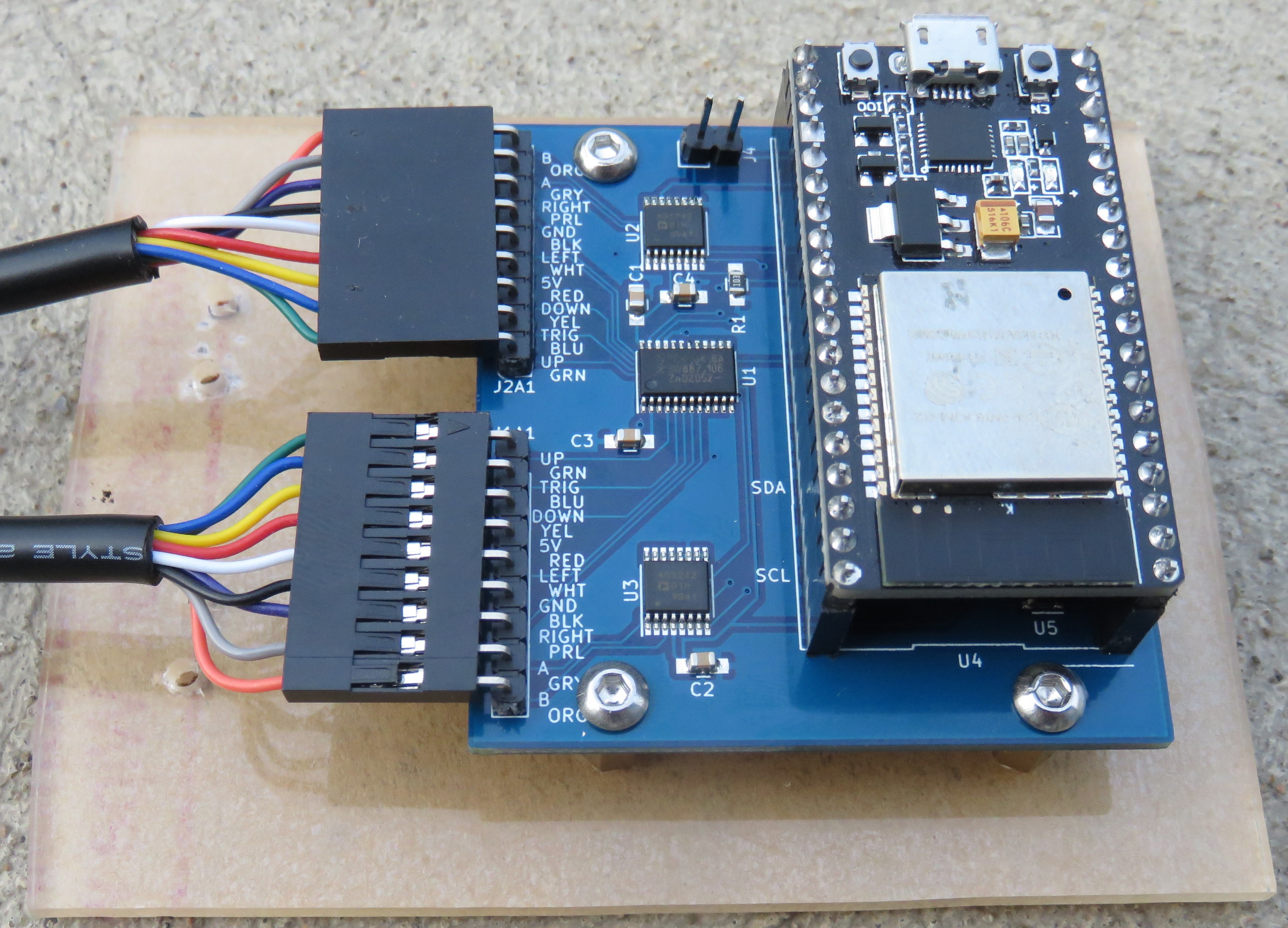
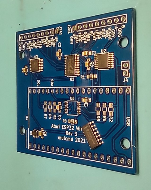
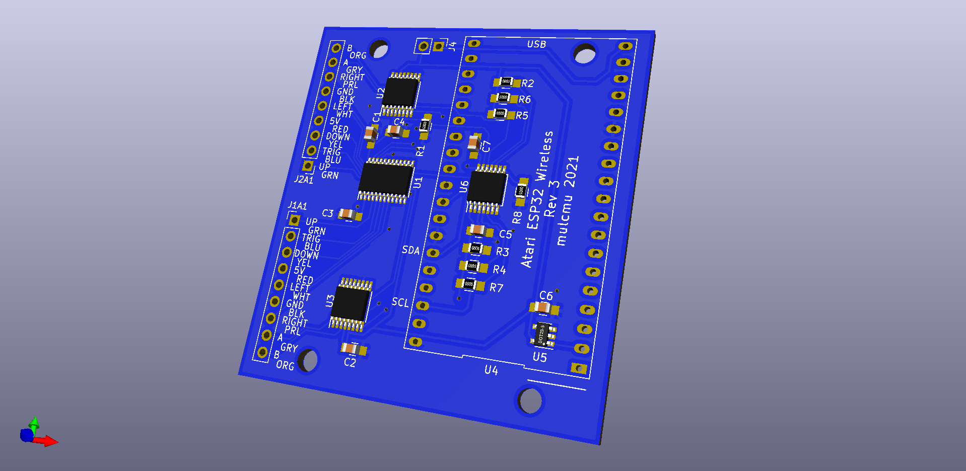
• Rev 3 Ready to Test

    mulcmu07/18/2021 at 22:03 0 comments

  • Options

    mulcmu07/17/2021 at 12:32 0 comments

    A few options to keep things moving:

    • Redo the board with SOIC footprint to use chips on hand
    • Mount SOIC chip on a breakout board and run wires to main PCB
    • Find the chip somewhere in TSSOP package
    • Find another pin equivalent replacement part

    All the big US catalog distributors were out of stock.  There were a few options on ebay but all international with long shipping estimates.  Octopart showed a few international distributors with parts in stock, again with long shipping times.  Octopart showed a few other US distributors with stock that I contacted.  Most had pretty high minimum order amounts, but I got lucky with South Electronics

    They waived the minimum order amount, accepted paypal payment, and shipped same day.  Parts delivered in 3 days!

  • U6 Footprint

    mulcmu07/12/2021 at 01:18 0 comments

    Rev 3 PCBs and back ordered 1M digital pots arrived earlier this week.  After the paste was down and most of the chips installed, ran into a problem with U6.  SOIC don't fit on TSSOP footprint.

  • Rev 3 PCB Ordered

    mulcmu06/26/2021 at 13:36 0 comments

    Finished routing Rev 3 PCB and placed order.

  • Power Managment

    mulcmu06/23/2021 at 01:55 0 comments

    If the Atari and the ESP are running on separate power supplies want to avoid back feeding the unpowered device.  I'm not sure what a reasonable power draw from the Atari is and the ESP could consume several hundred mA.  The i2c level shifter output enable will be controlled by ESP logic.  A voltage supervisor was added to the Atari 5V supply to disable the ESP 3.3V regulator until Atari is powered.  So if just ESP is powered, it won't start until Atari is powered.  If just Atari is powered, i2c chip will be tri-state.

    Rev 3 of schematic posted to Github.

  • Rev 3 Progress

    mulcmu06/21/2021 at 03:34 0 comments

    Uploaded video demo:  https://cdn.hackaday.io/files/1797867691964224/Rev%202.1%20Demo%20Small.mp4

    Going to use a dedicated level shifting chip TI TXS0104E for the i2c level shifting.  This has 4 signals so will let the IO expander handle SCL SDA, the IO expander interrupt feedback, and feedback if the Atari is powered.  While picking this chip noticed the 1M digital pots weren't in stock any longer at Digikey in TSSOP package...

  • Full Operation

    mulcmu06/18/2021 at 02:15 0 comments

    After a quick mini project to make a 3d printed back shell for the joystick connector, wired up a Revision 2 PCB with extra interface for the i2c level shifting.  An extra strip board pcb was created with 2n7000 level shifters.  The PCB 3.3V rail was hooked up to 5V making the whole PCB work at 5V.  Not very pretty but everything worked when tested with 800XL and Pac-Man / Super Breakout.

  • PCB Rev 3

    mulcmu06/15/2021 at 02:00 0 comments

    The Rev 2 PCB arrived this afternoon, but the Rev 3 design was started a few hours later....

    Reviewing the AD5242 datasheet shows the wiper/leg voltages need to be within the supply voltage range.  The current design has the digital pots powered from 3.3v rail to avoid level shifting the i2c bus.  But the Atari needs 5v to the digital pot.  I removed the 1M AD5242 chip, mounted it on a breakout board, and tested operation in bread board.  Test circuit with the digital pot setup with another resistor as a voltage divider resulted in the observed behavior.  Works when powered from 5V,  When powered by 3.3V with 5V to the digital pot, no good.

    So Rev 3 will power all of the i2c chips with +5V and still have one bus with level shifters for the ESP.

    Digikey has the AD5242 1M back in stock but the price is up to $4.24 each for 1-9 pcs.

  • Milestone

    mulcmu06/14/2021 at 00:13 0 comments

    Test code is working using the https://github.com/hrgraf/ESP32Wiimote Arduino library for one joystick.  The direction and trigger buttons are working, responsiveness is great. But still not getting the paddle inputs on Super Break out.  The 100k pot is always full left and 1M pot is always full right on the screen.  Test code uses the WiiMote ± buttons to adjust the pot output.  Resistance change looks fine with the multi-meter.

  • PCB Rev 2

    mulcmu06/09/2021 at 12:02 0 comments

    One leg of the digital pot needed to be tied to +5 and the other end floating.  Rev 1 of the PCB connected the leg to ground instead.  I was able to rework the current board to correct the but put a lot of heat into the chip getting the enamel wire soldered.  Doesn't seem like they are covering full range of resistance any more....

    Also added a jumper to allow Atari to power the ESP32 dev board.  So far I've been powering with separate USB power supply.

    Rev 2 PCB board order was placed last night.