Crossfade demo:
0%
0%
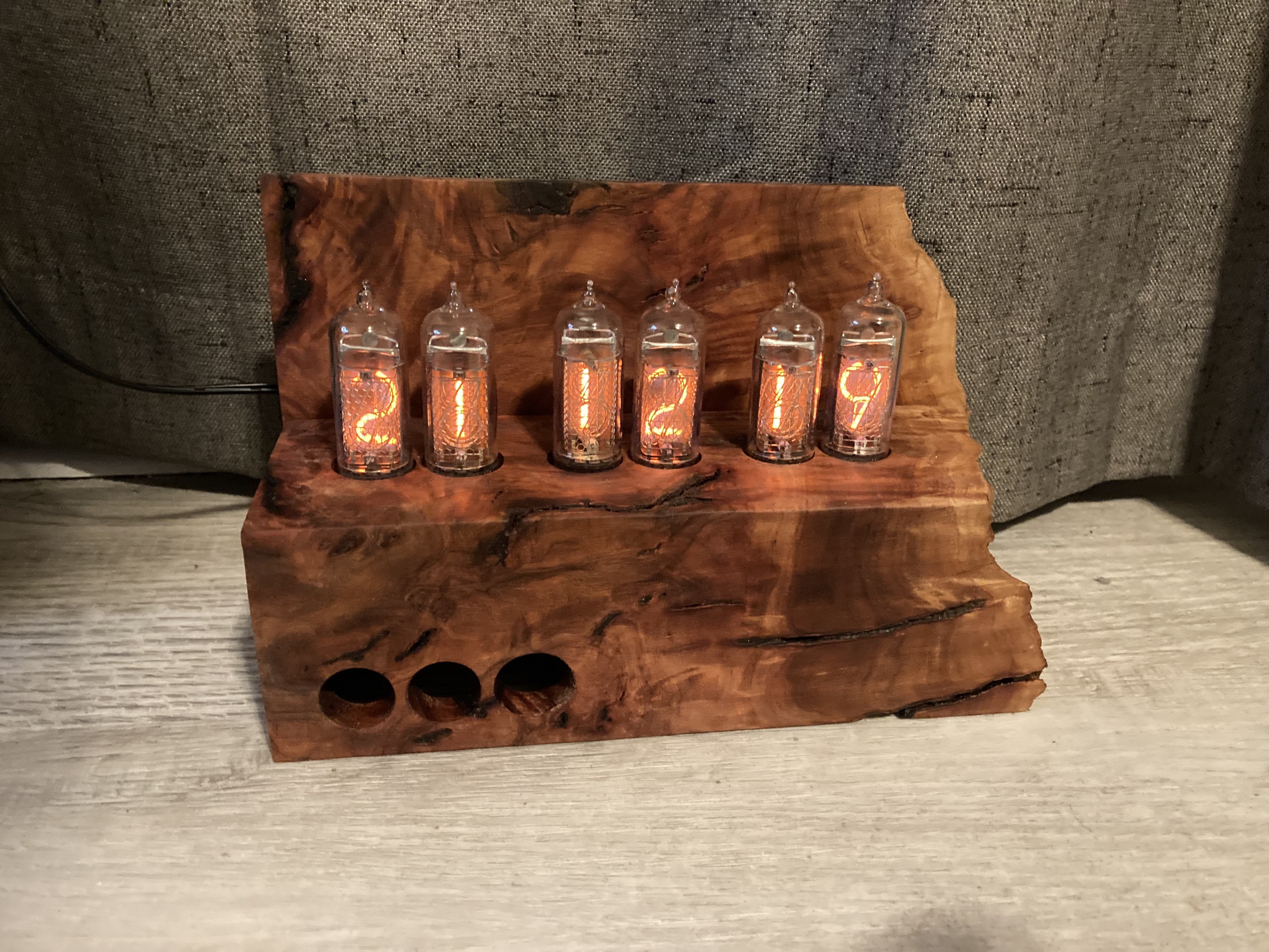
Just Another Nixie Clock
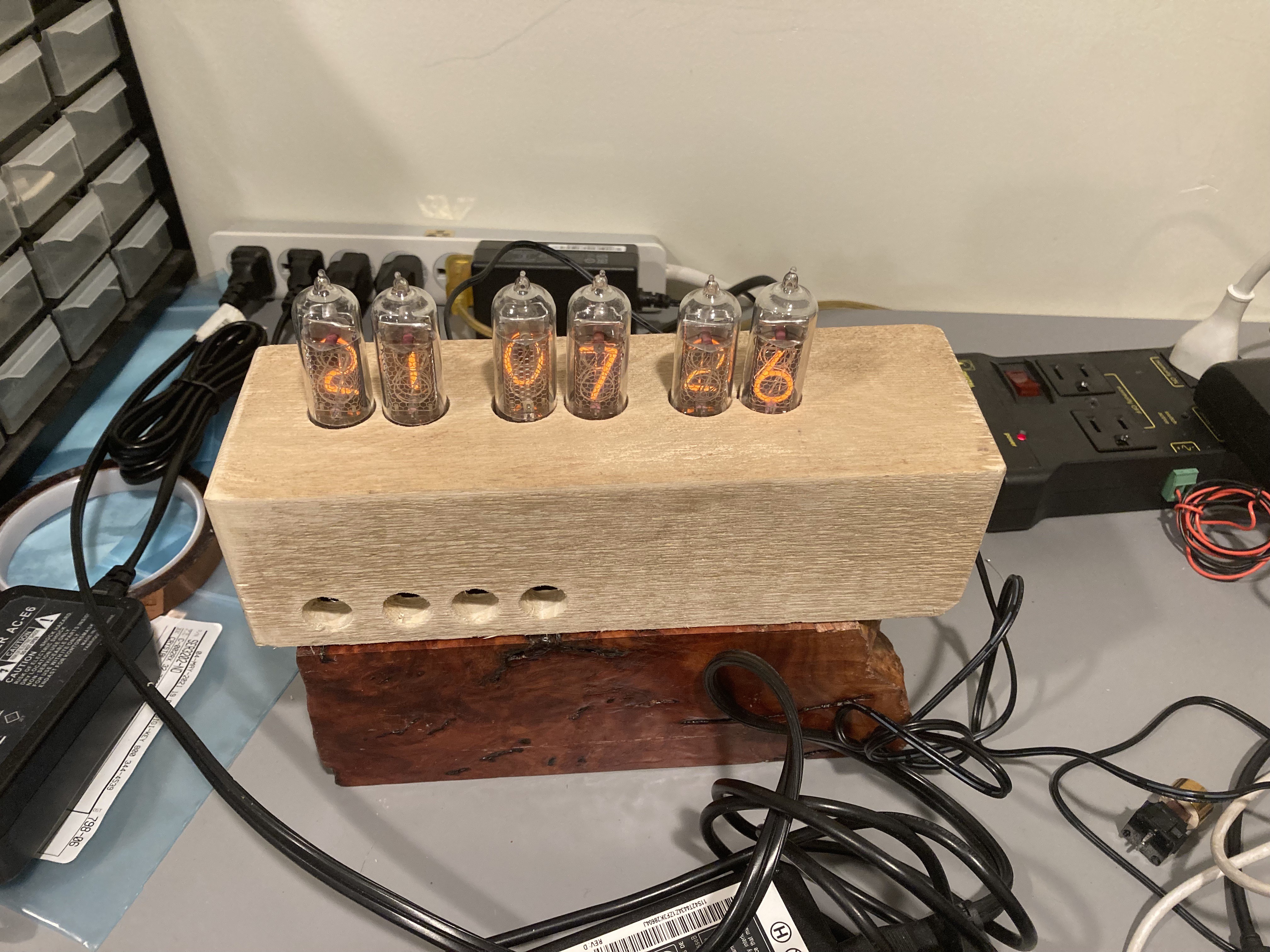
An arduino based multiplexed, cross-fading IN-14 Nixie tube clock.
Become a Hackaday.io member
Already have an account? Log in.
Just one more thing
To make the experience fit your profile, pick a username and tell us what interests you.
Pick an awesome username
hackaday.io/
Your profile's URL: hackaday.io/username. Max 25 alphanumeric characters.
Pick a few interests
Projects that share your interests
People that share your interests
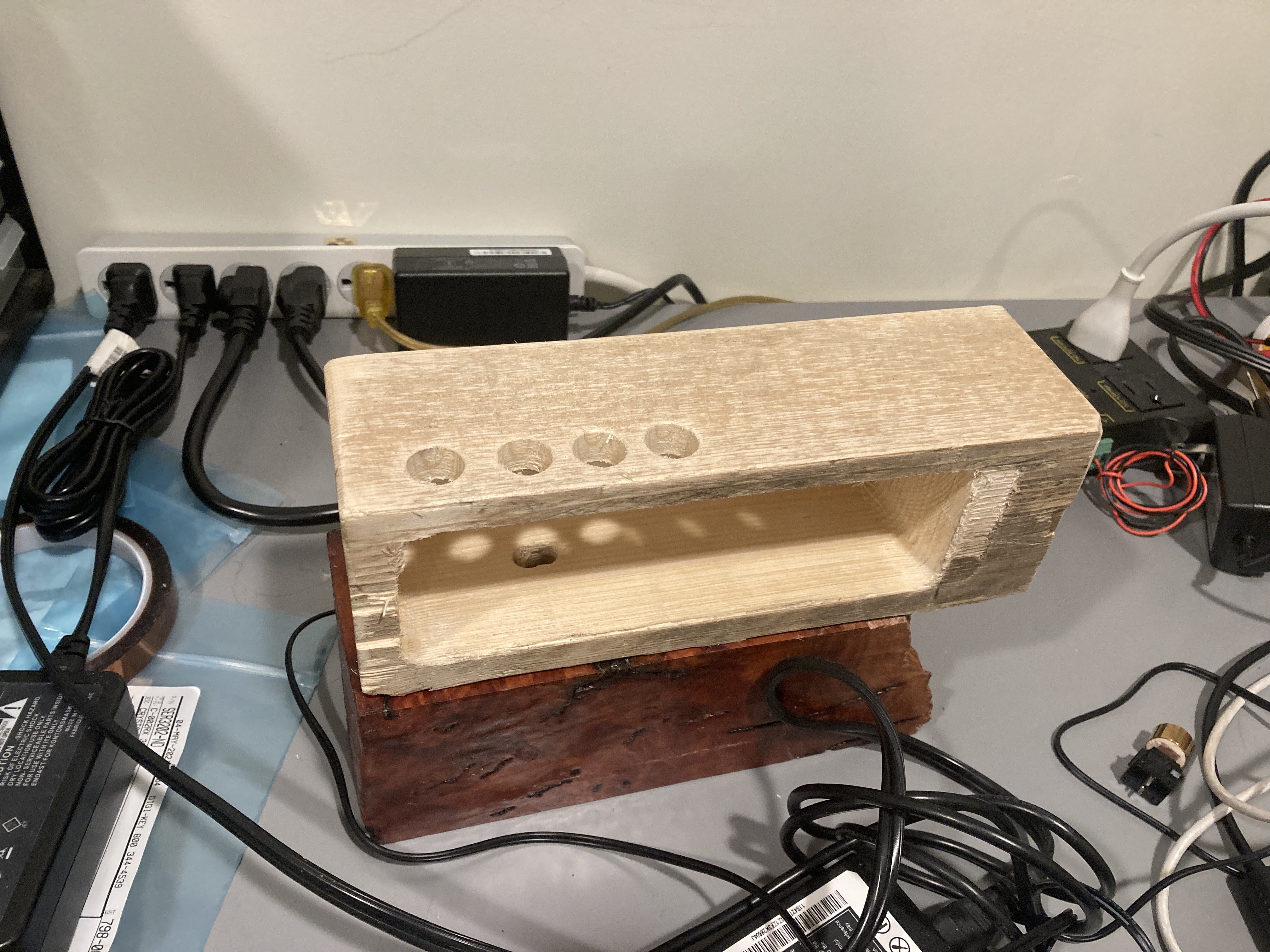
 And the buttons! I haven't mounted them in the clock, but I bought a piece of brass pipe from a big box home improvement store and turned it on my lathe before I moved. I FINALLY got around to trimming the watch hands I got from my former FIL down, filling the turned brass with FIMO (polymer clay) and placing the hands, watch gear, and pressing the key switch into the back and baking them. Voila! 30 minutes later, custom buttons. Again, really happy with how this worked out. The gear is the "settings" button, the 11:55 is the decrease button, and the 12:05 is the increase button.
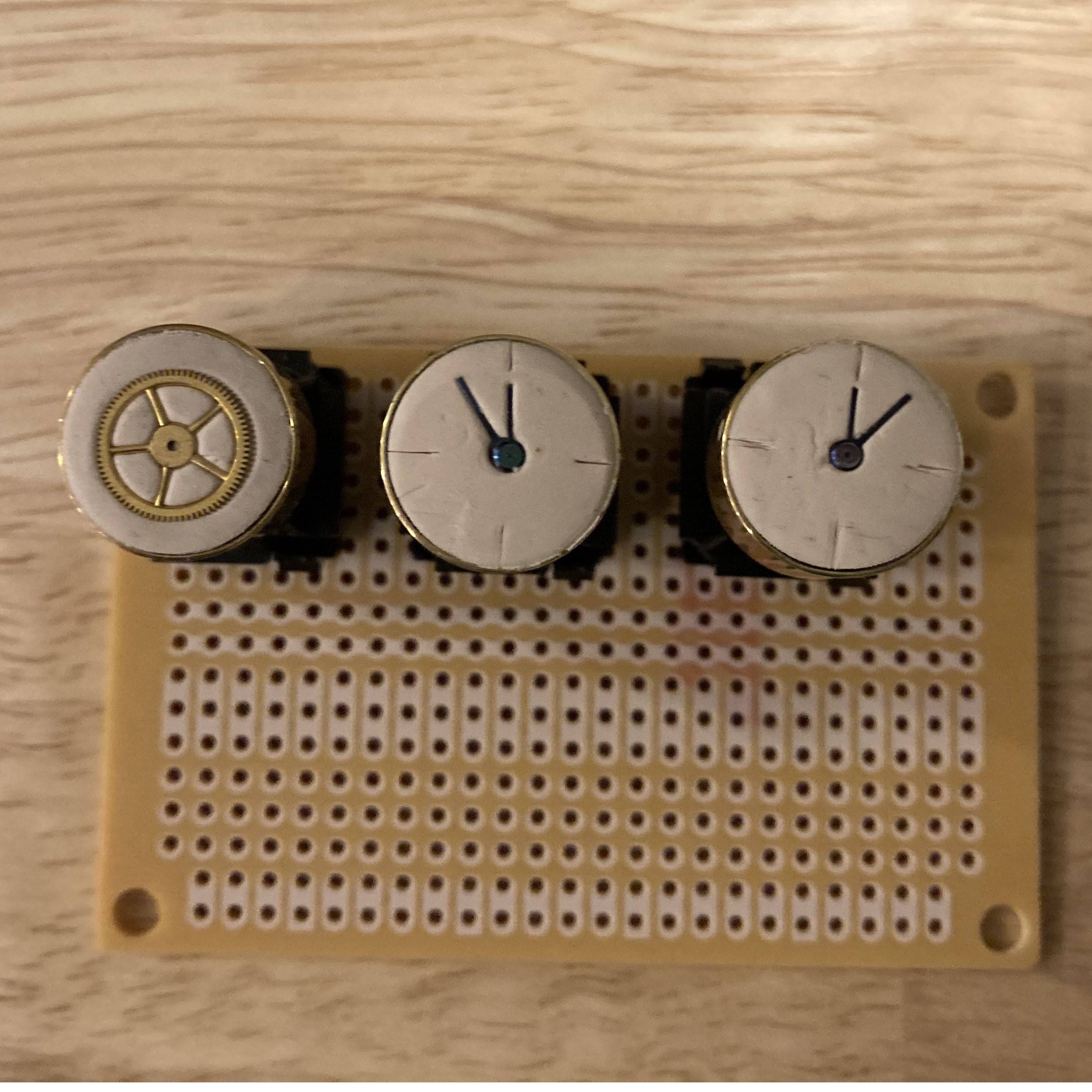

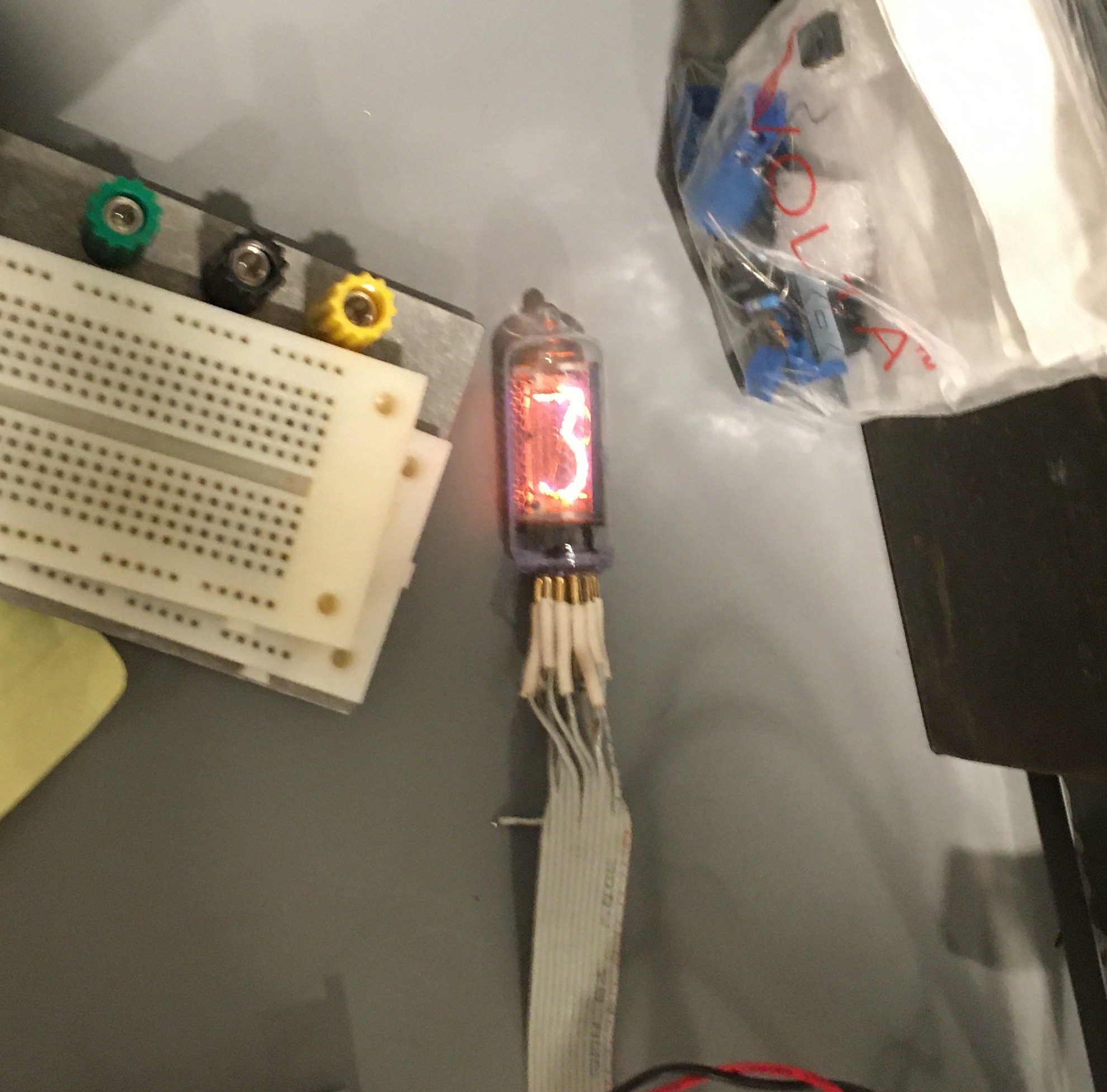 IN-8's are the same size as the IN-14 but with pins instead of wires and normal 5's instead of upside-down 2's. They will be used in my next nixie project, where I focus more on the style than the electronics.
 Nick Sayer
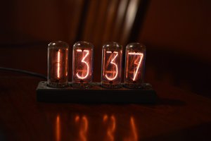
 Gary Marsh
 zaphod
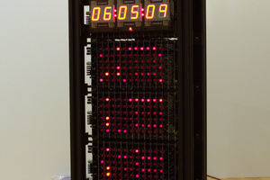
 Ted Yapo