I was working on this project from time to time for several months already. During that time, few weeks I spent waiting for the board to arrive from JLCPCB. I ordered them partially assembled with whatever was available to assemble. Last few afternoons was soldering those elements that JLCPCB was unable to solder with their basic service (or at all?). Today I solved last significant problem with microSD card slot, so I am now able to boot automatically into OS that used to work on Raspberry Pi 4 before. In the meantime I also tested RPIBOOT jumper, so it is now confirmed that shorting this when connecting the power results in jumping into rpiboot mode of bootloader, so it should be possible to flash eMMC from there. I have CM4Lite, though, so was not able to confirm that.
These are the things that I was able to verify till now:
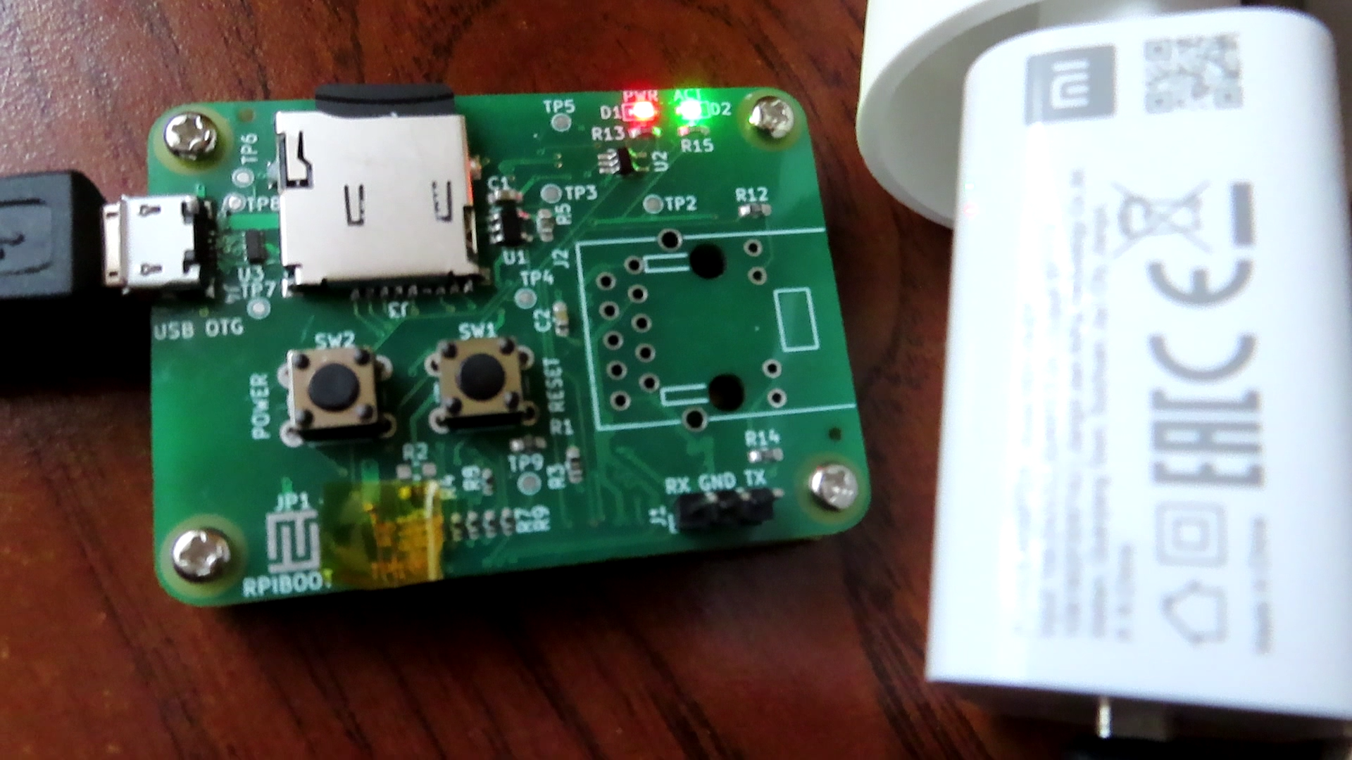
- With testpoints it is possible to verify that power to SD card slot can be cut by CM4
- PWR LED indicates that board is powered
- ACT LED shows that some activity is going on (was not blinking when I had SD issue - weird)
- RPIBOOT goes into BCM2711 Boot, when shorted
- USB connector delivers power to board, but also allow USB communication to SoC
- UART shows system log, when booting Linux
- After system startup it is possible to interact with the system
- Ethernet link is going up and green LED on connector indicates that
- Ethernet activity LED blinks, when something is going on
- Ethernet link works, when connected to PC sharing its connection
As can be seen above, generally everything is working. But this cannot be so sweet in first iteration. In the meantime, I identified some problems, that I try to keep track of on Github. Most significant one is 5V power rail being too thin at the very short distance, so it is possible that two Hirose pins are more loaded with current than the rest. I am not an expert in electronics, but on my first prototype I made a jumper with wire for a reason that turned out to be my mistake. Due to that trace width problem, I left this bridge, just in case.
Other minor errors I noticed are as of now:
- No vias near USB testpoints on production files (KiCAD source was fine at all times!).
- Very tight fitting of Ethernet connector. Reason for this problem was me, migrating from other connector of same manufacturer, that was almost the same, excluding 0.1 mm diameter of shield mounting hole and way more obvious LED pin locations.
- RPIBOOT jumper is hard to short.
- Soldermask around vias - some are not under soldermask, some are. It is not a problem, but is ugly and unprofessional :)
Discussions
Become a Hackaday.io Member
Create an account to leave a comment. Already have an account? Log In.