 Ahmed Oyenuga
I designed the first version of the Ahmsville Dial a little more than a year back, and I’ve loved using it, despite its limitations.
Last year I finally decided to update the dial, so I took all my experience with it, and put it into the development of the version two, with very specific goals in mind, my first goal was to create multiple version of the dial to cater to different types of users, my second goal was to make the dial operate in both wired and wirelessly modes, my third goal was to make the dial extremely easy to use even for people with zero programing skills, this largely meant I had to develop a companion app for the dial, the last goal I had was to give the dial context awareness, which simply means having the dial automatically switch its configuration to match whatever software your using it with, this way, the dial can be programmed to do different things within different applications...this feature is one of many enabled by the companion app.
Ahmsville Dial V2 follows the same design philosophy as the version one, only with a higher resolution encoder, new hardware features, improved and streamlined code, simplified assembly process and the aforementioned companion app for windows users.

Ahmsville Dial V2 Variants
Ahmsville Dial V2 Project Video
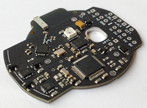
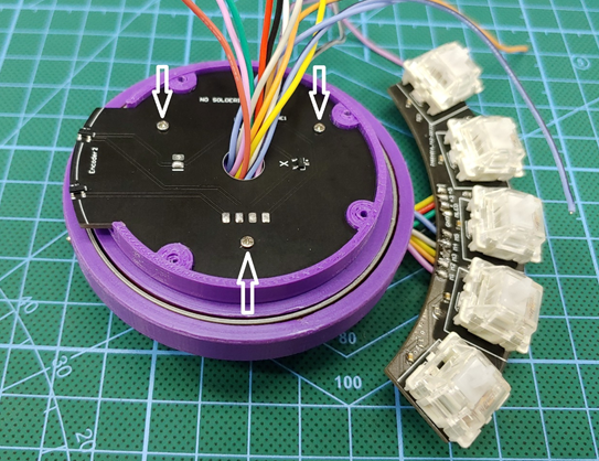
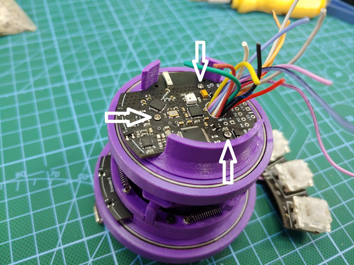
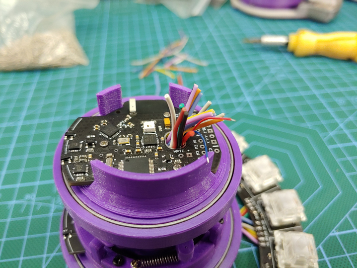
The first big change to the system is in the circuit, the dial now uses the ATSAMD21G chip, which is the same chip used in the Arduino zero boards, and a lot of the MKR series boards, compared with the ATMEGA32u4 used in the previous version, this chip is much faster and generally better suited to handle all the new features of the Dial.

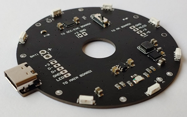
Ahmsville Dial V2 Boards from jlcpcb.com
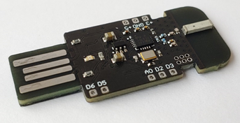
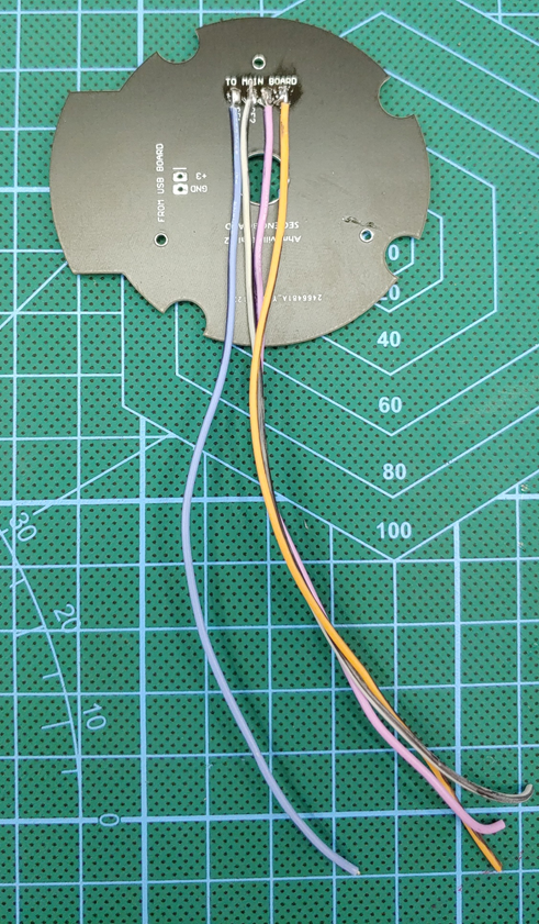
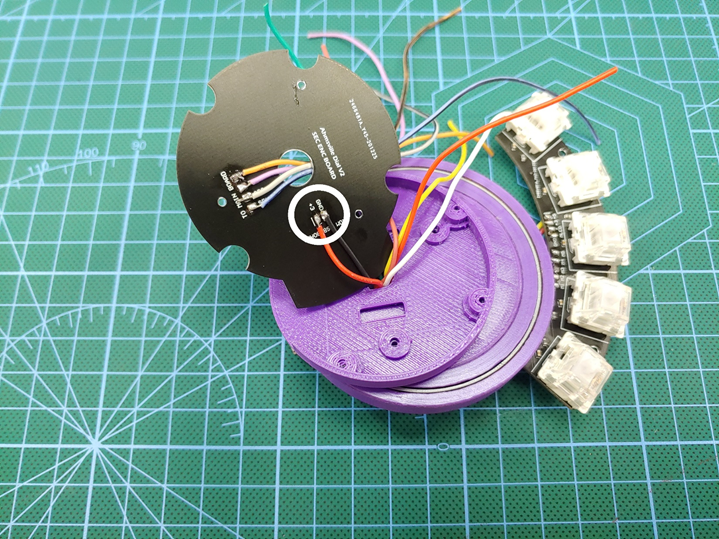
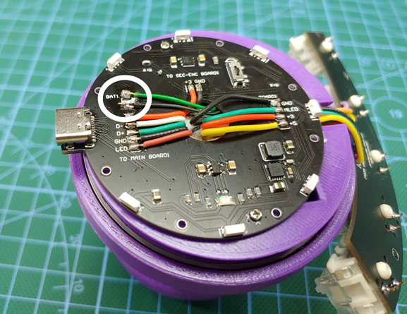
Another change to the system is the inclusion of a NRF24 wireless chip, with this, the dial is now able to operate wirelessly. I went this route because Bluetooth hid just wasn’t going to cut it, especially for the more advanced features I implemented in this version of the dial, the dial can also be used wired via the now included USB type C port, I have also made sure that there are no tradeoffs functionally between the wired and wireless modes.so switching between them is as simple as unplugging the USB cable from the PC and plugging in the wireless adapter or vice versa, the software on the dial is smart enough to handle the switching between all the connections.
The dial, although primarily designed for your PC, can also be used to control other devices, the wireless adapter which feature an ATMEGA32u4 has some of its pins broken out to allow for easy integration into other electronics systems.

Wireless Communication Via NRF24
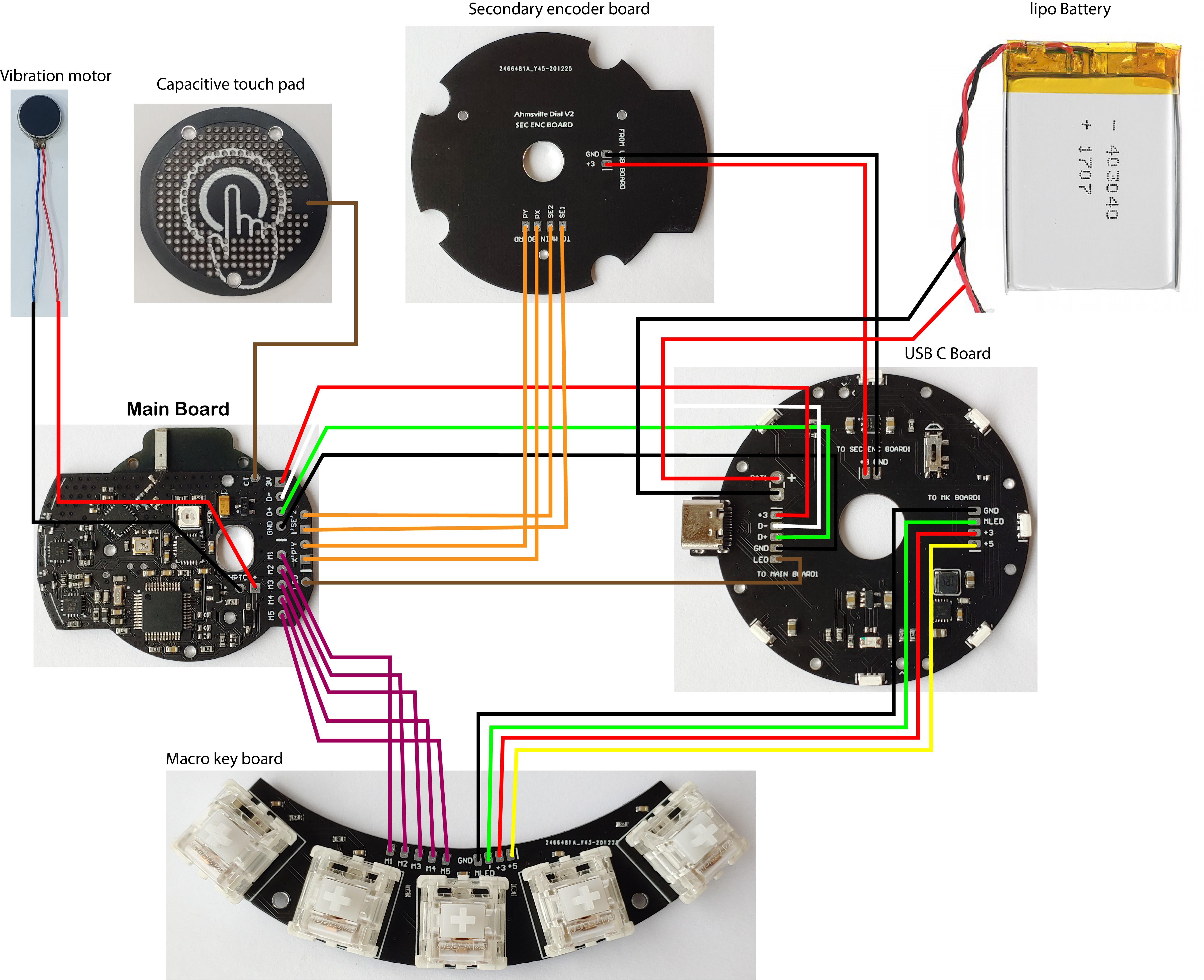
Dial Hardware Features
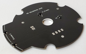
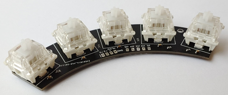
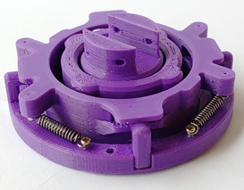
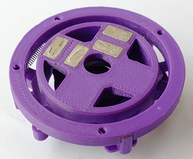
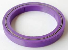
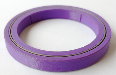
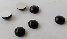
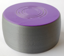
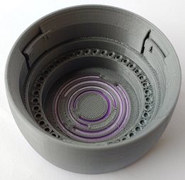
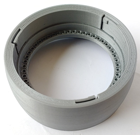
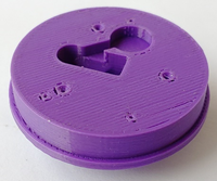
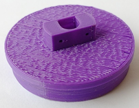
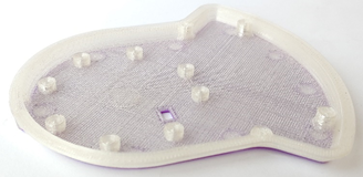
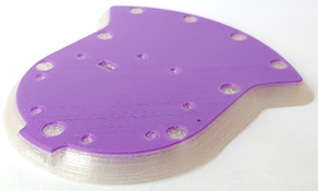
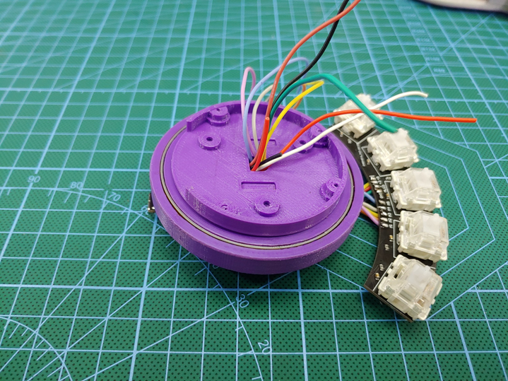
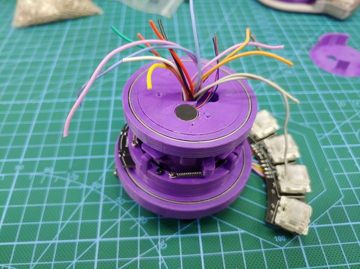
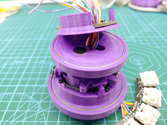
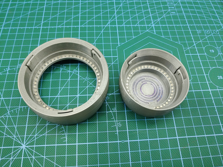
The Knob (Magnetic Rotary Encoder)
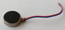
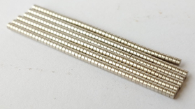
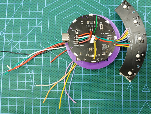
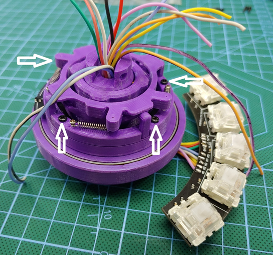
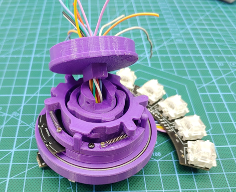
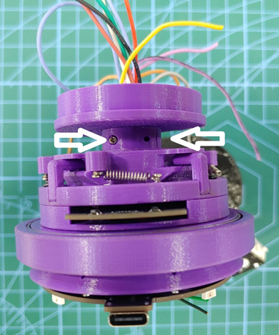
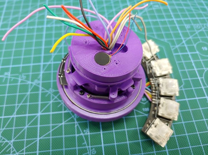
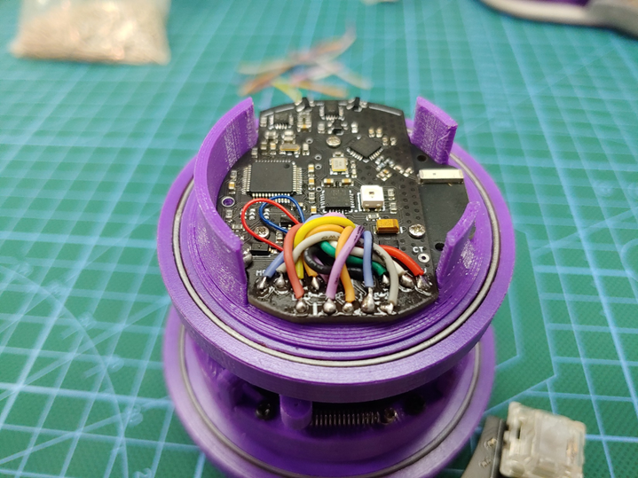
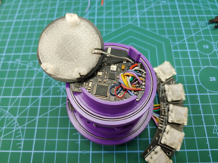
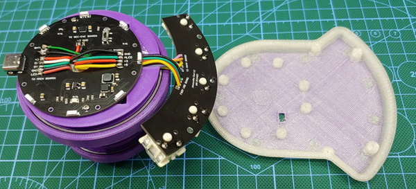
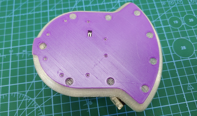
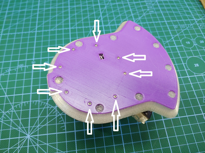
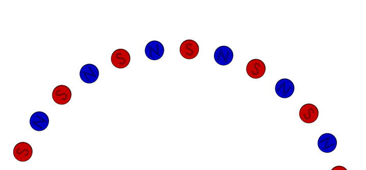
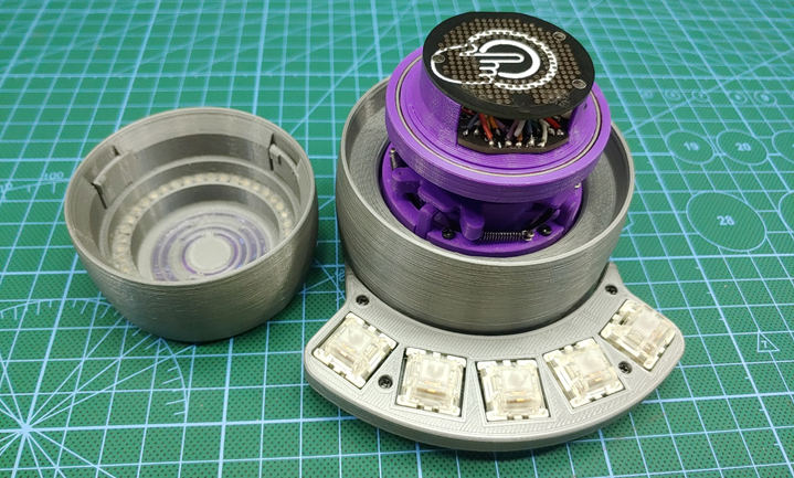
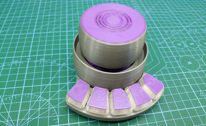
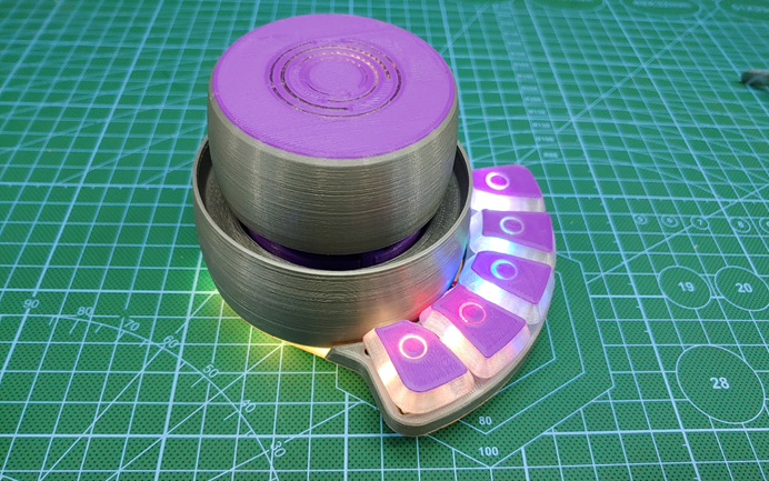
The rotary encoding method that’s used in the dial is one of my very own designs, it’s a ball bearing assisted, high resolution and contactless magnetic rotary encoder, the knob is fitted with a ring of tiny neodymium magnets in an alternating magnetic pole configuration; on the main board there are two linear hall effect sensors used to read the analog values on the magnets. This system allows the knob to operate through a ball bearing without ever touching the electronics, this makes for a very smooth feeling knob and is also one of the reasons the dial is so durable. This trend of isolating all moving parts from the electronics...
Read more »


 dariocose
 Elton
Elton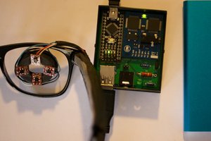
 Malte
Malte
 Nick Velasquez