 Kevin Kadooka
Ah, finally - some progress to report. All of the parts and pieces are in at last. The pieces I was anticipating the most were definitely the 3D printed pieces. All were printed in Shapeways' MJF plastic, which I have had numerous excellent experiences with. I used their medium-fast service and I had parts on my doorstep within 2 weeks. I also ordered one translucent SLA part (a replacement frameline window for the Canon 7 - mine crumbled into dust during disassembly), which took a couple more days to print and be processed. If I had printed everything in MJF, I'm sure it would have been even faster.
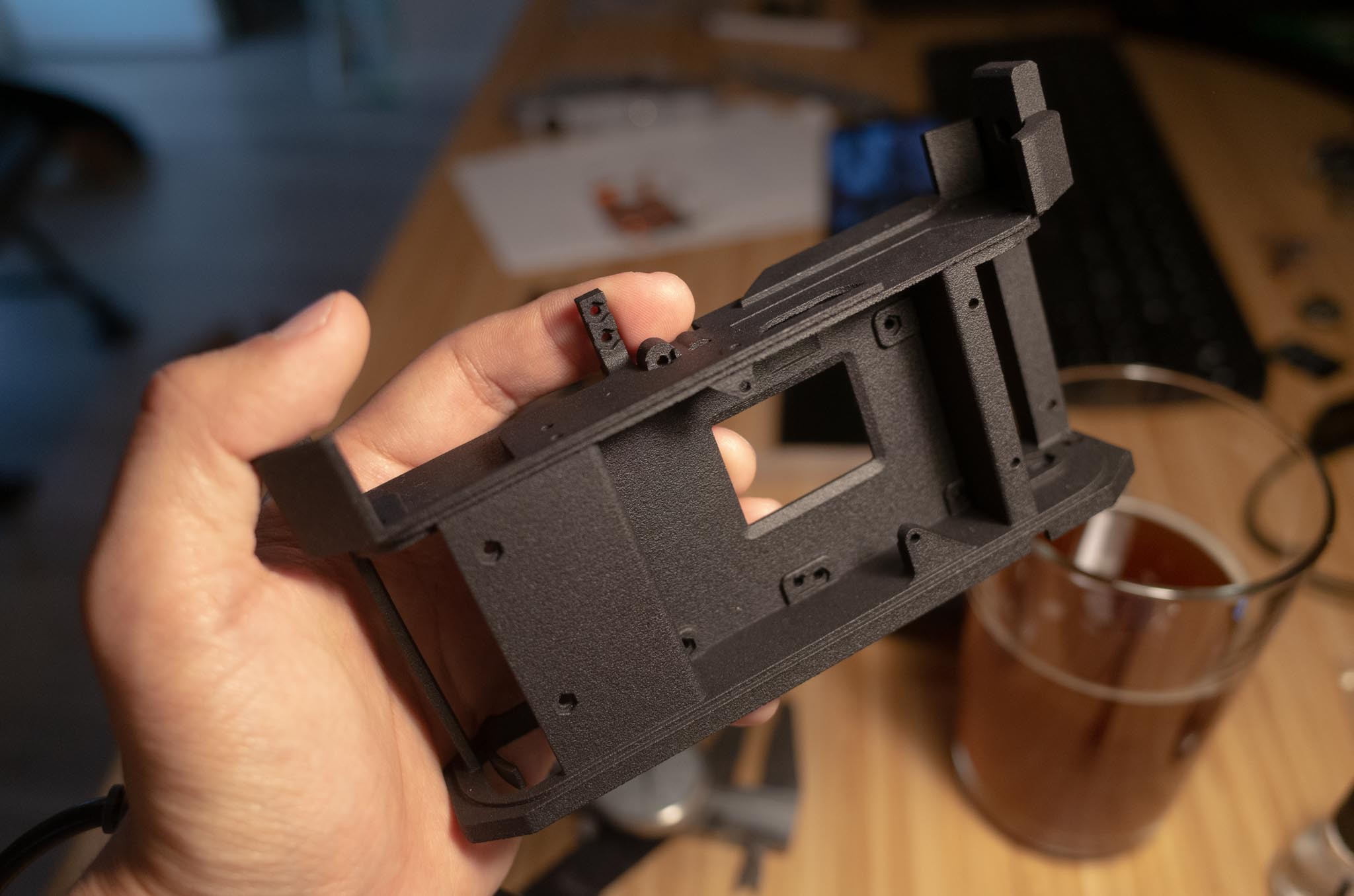
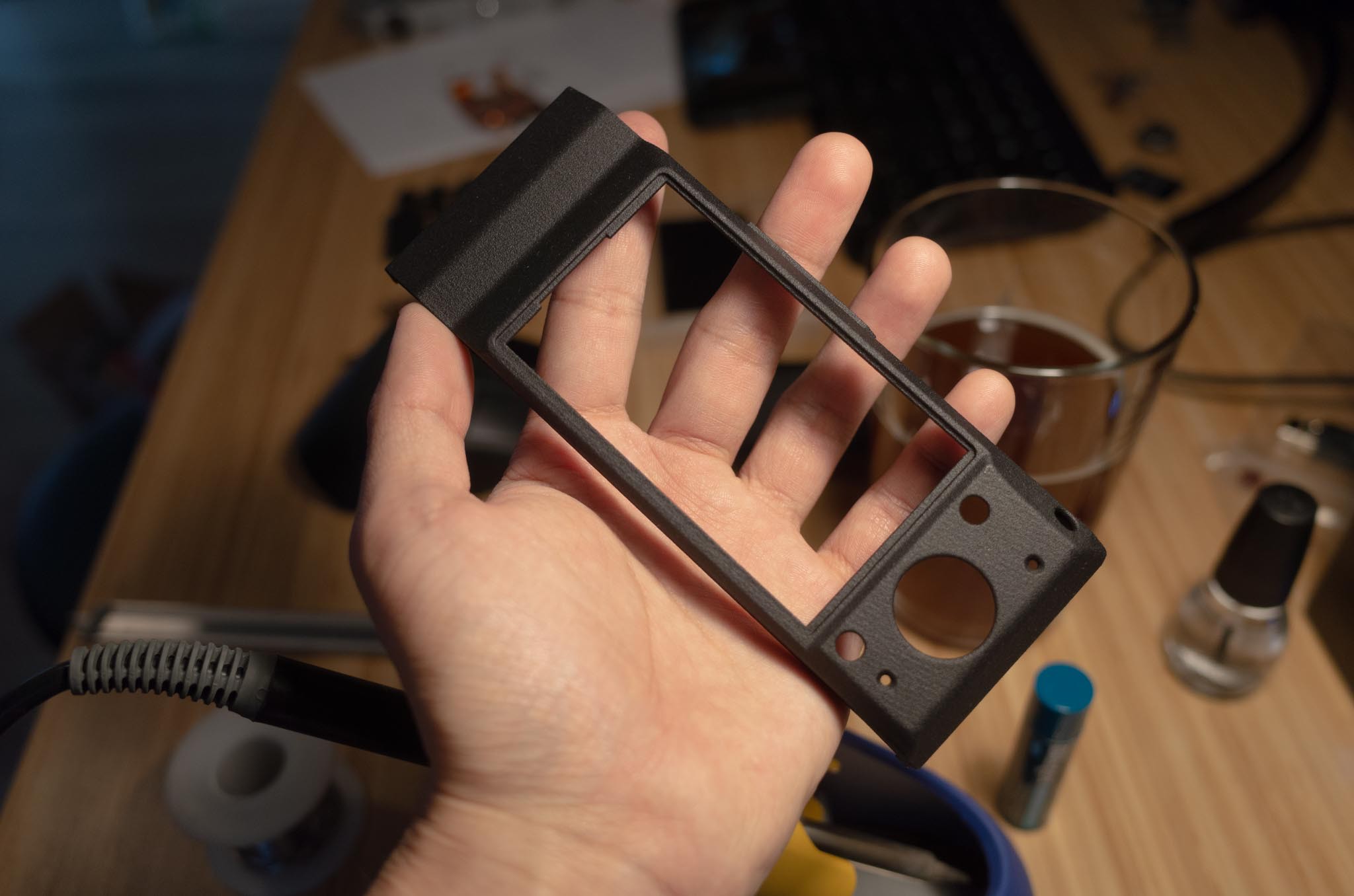

I've already started the process of putting the camera together, but there have been two major setbacks:
- Something in the NEX-5 donor electronics gave up the ghost. I've not been so kind to it (generally manhandling the electronics without any anti-static measures) I think the nail in the coffin was plugging in the battery without properly insulating all of the flying wires and exposed PCBs. A short probably occurred which has sent the camera to an early grave. RIP, you will be missed. Anyway, I bought a new donor camera - there is no shortage of these things.
- I bought the wrong freaking size of M1.6 hex nuts. This is quite a sordid tale. First, I wanted some thin M1.6 hex nuts, under DIN 439B standard. Those things are unobtanium, it seems. And when they are available, sellers want an arm and a leg for them ($3-4 a pop! And I stupidly designed this thing needing 26 of them...). I finally found them at a decent price, but the seller waited a full week to tell me that they were out of stock and not planning on backordering any. So, I decided to suck it up and buy some regular M1.6 hex nuts (the DIN 934B standard) and shave them down where necessary (there are only a few places where their thickness is actually important). I decided to go the cheapest possible route and buy some on Amazon Prime, not realizing that they were of a nonstandard size. See, standard M1.6 nuts are nominally 3.2 mm flat-to-flat and 1.3 mm thick. These ones I got on Amazon were 2.5 mm flat-to-flat and 1.5 mm thick. This meant that the hex-shaped features I designed in the 3D prints did not hold prevent them from rotating at all. A copious amount of CA glue was needed to fill in the gaps and hold the nuts in place, which worked half of the time. Another quarter of the time, the nuts would simply break loose under torque, or a stray glob of CA glue would gum up the threads. The lesson here? Always check availability of components before you design around them. I took the availability of a simple hex nut for granted, and it keeps biting me in the ass (hence the title).
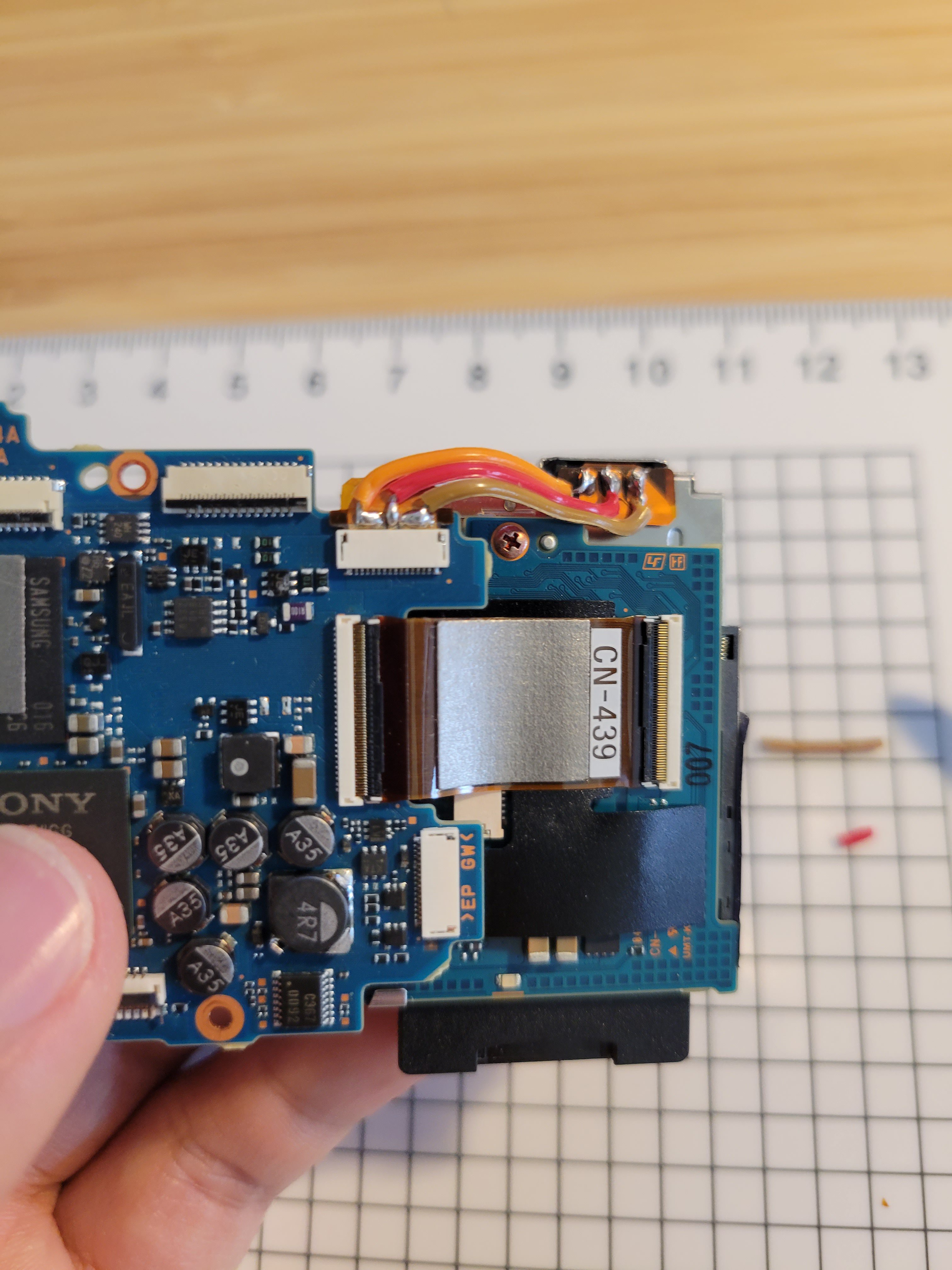
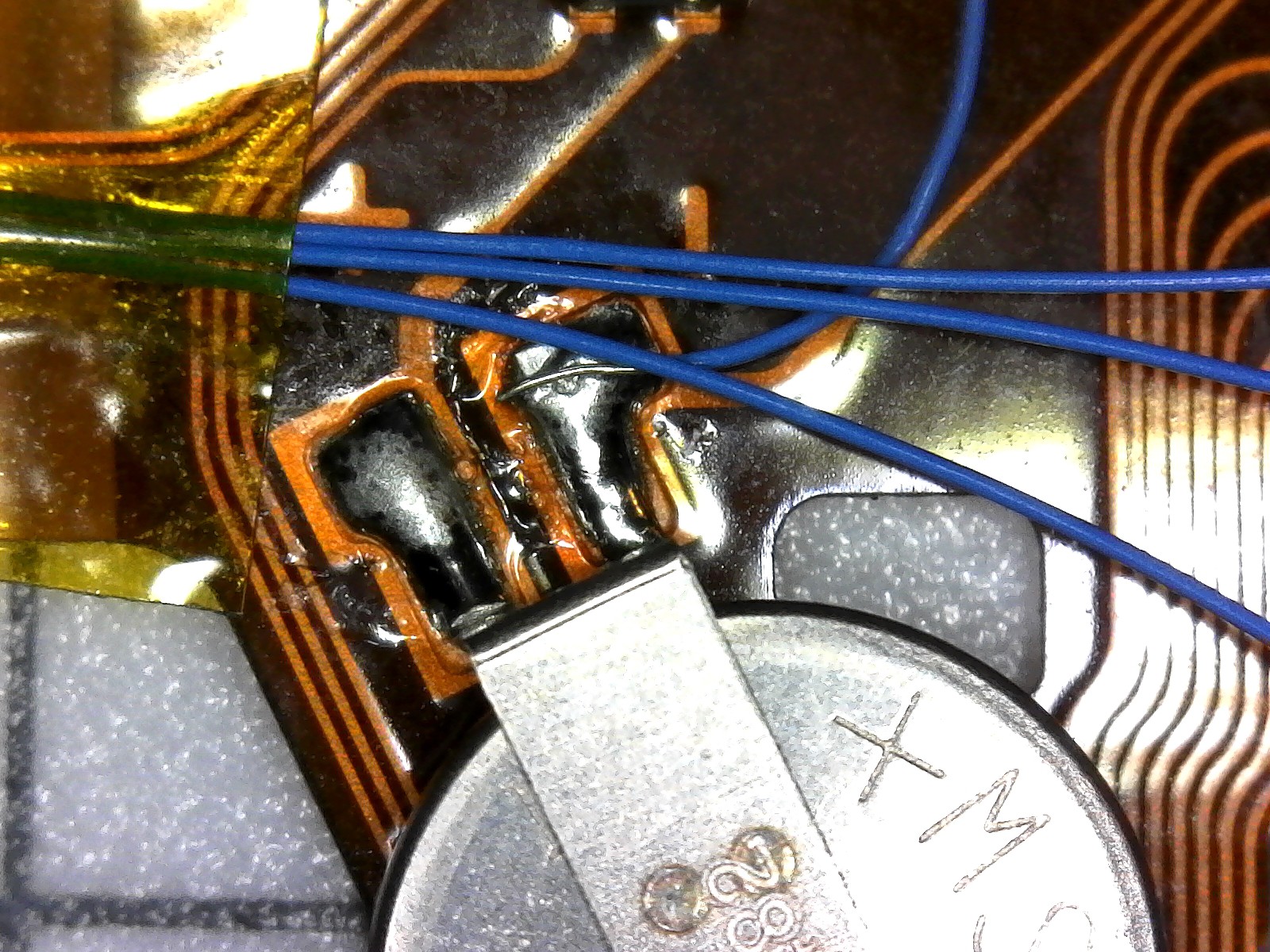
There was some success, however, with doing some of the electrical setup for the conversion. First, a bespoke solution is needed to connect the battery to the motherboard. To fit inside the Canon 7, the battery compartment of the NEX has to be rotated 90 degrees and sit just behind the motherboard, as shown below. The original flex connector is not meant to contort in such ways, so I snipped off the end and soldered 3 strands of a flat ribbon cable between it and the battery contacts. It's a tedious and careful job to strip away enough of the polyamide insulation on the flex circuit to expose enough bare area to solder to.
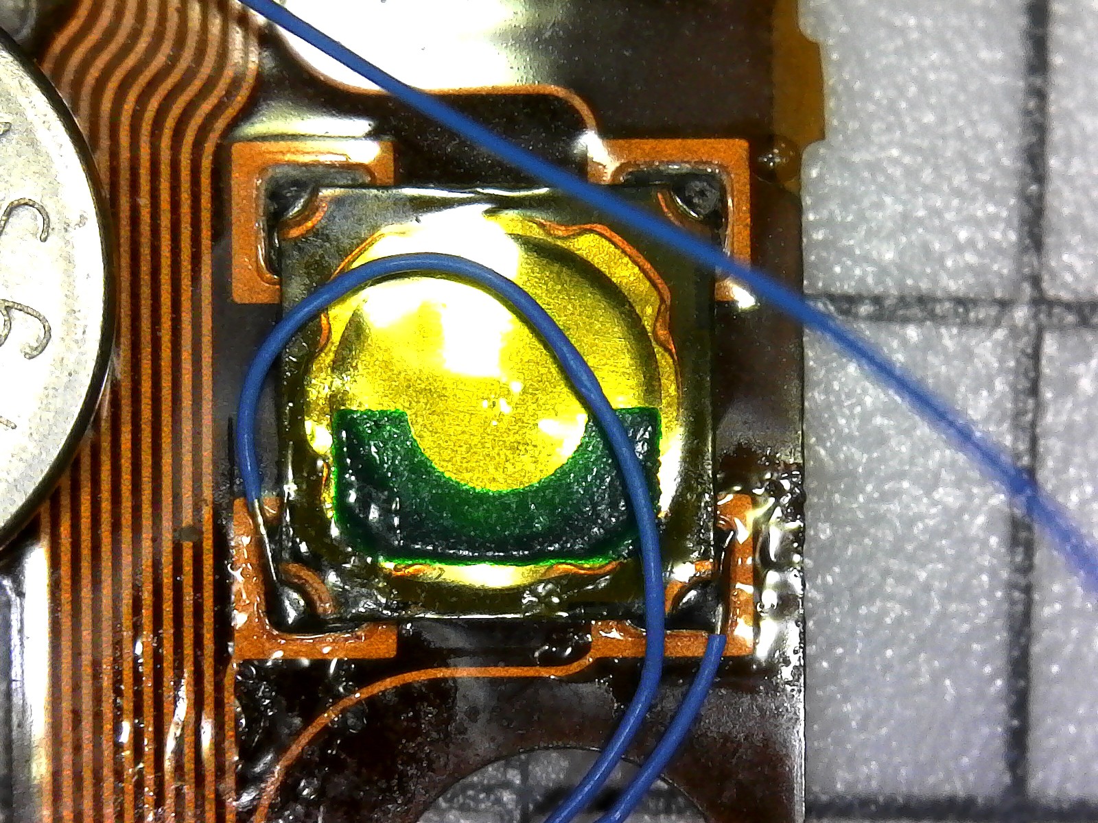
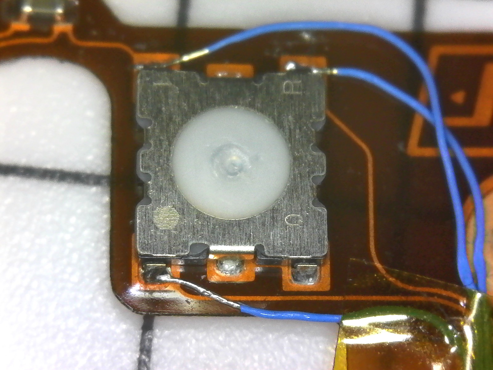
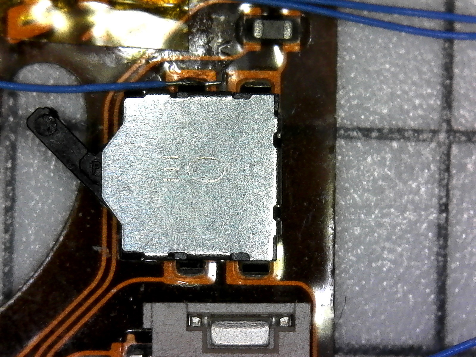
The top flex circuit of the NEX has some very important features: it holds the power switch, shutter button, and a button to enter playback mode. These will all be "broken out" via flying wires to locations easily accessible under the Canon 7's top shell (the exploded diagrams in the last entry may help to explain this). More tedium, but after a bunch of squinting and careful tweezer action, 38 AWG leads have been attached to the proper points on the flex circuit:
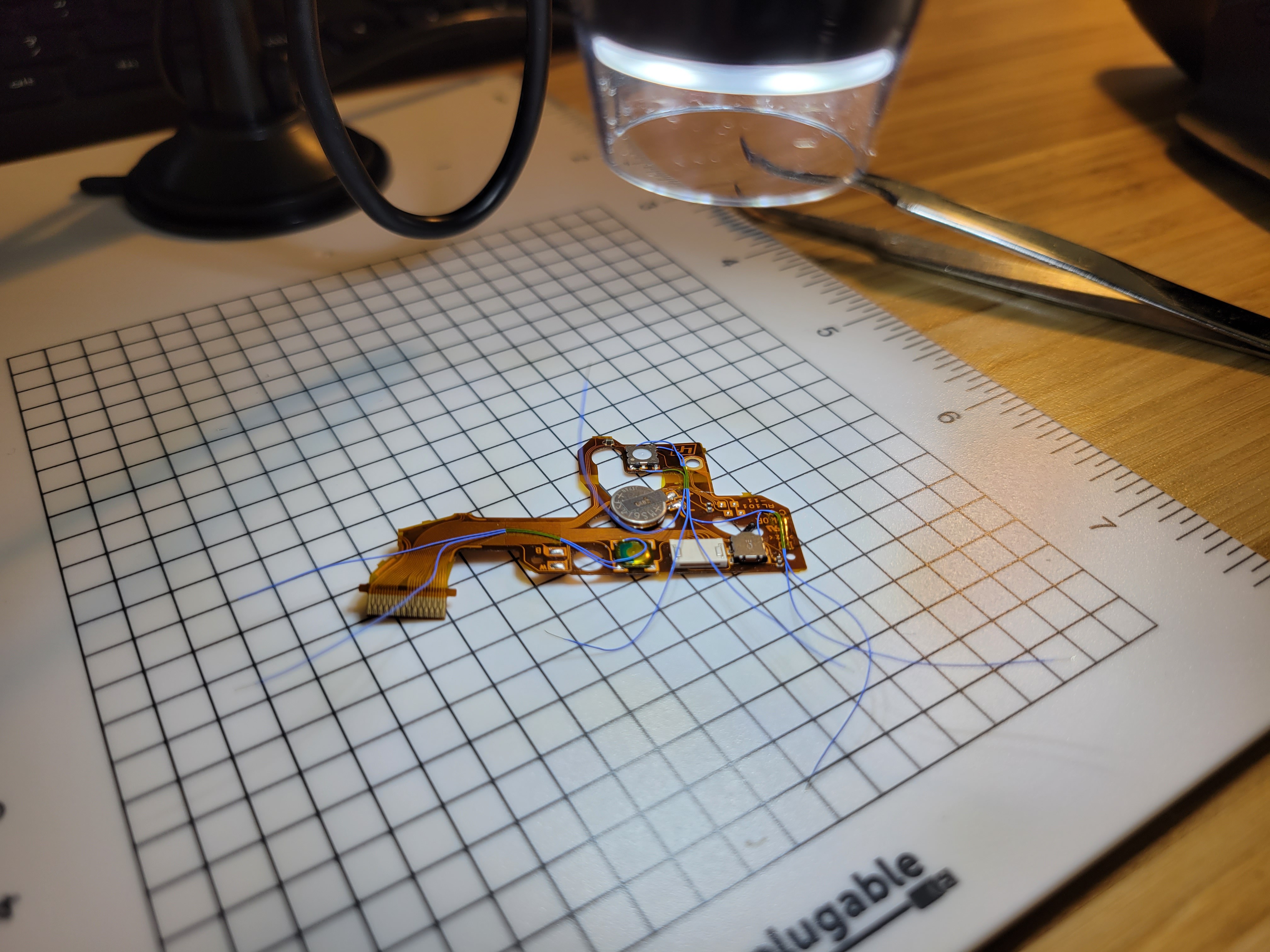
For reference, these are the specific points that need to be broken out:
Discussions
Become a Hackaday.io Member
Create an account to leave a comment. Already have an account? Log In.