 Kevin Kadooka
Here's the idea. Let's make a digital rangefinder camera by combining the electronic bits of a Sony NEX-5 (the OG version circa 2010-2011) and the body and rangefinder unit pulled from a Canon 7.
I should point off off the bat that this isn't something new - there have been various successful efforts to combine film cameras and digital sensors (see: https://frankencamera.wordpress.com/2014/08/30/the-making-of-frankencamera/). My tenuous claim to originality is that nobody (to my knowledge) has done this to an Leica Thread Mount (LTM) rangefinder, let alone the Canon 7.
Perhaps the best way to introduce this project would be to answer the "whys":
- Why build a digital rangefinder camera? I don't know, for fun, I guess? Digital rangefinder cameras exist, and if you were so motivated, you could just buy one off the shelf. However, the cheapest regular production digital rangefinder is probably the Epson RD-1 (which had a heroically long production run for a digital camera, from 2004-2014) - which you would struggle to find for under $1,000 on eBay. All for 6.1 megapixels. On the other end of the spectrum you have the PIXII ($3,300, with... interesting reviews) or the Leica M8 or later, which when new, will cost well north of $5,000. Before being usurped by the single-lens reflex, rangefinders were the norm. These days they are novel and unique, offering a different shooting experience. This project should cost much, much less than any of the aforementioned cameras, and might open that experience to those who don't have wads of cash burning Leica-sized holes in their pockets, and don't mind doing a little bit of tinkering.
- Why the Canon 7? Well, there are several reasons:
- They are cheap - you can find "for parts" cameras on eBay for as little as $50, and working examples are closer to $150, including shipping.
- They are plentiful - Canon made well over 100,000 of these cameras in the 1960's and 70's, so I don't feel too bad about chopping one up.
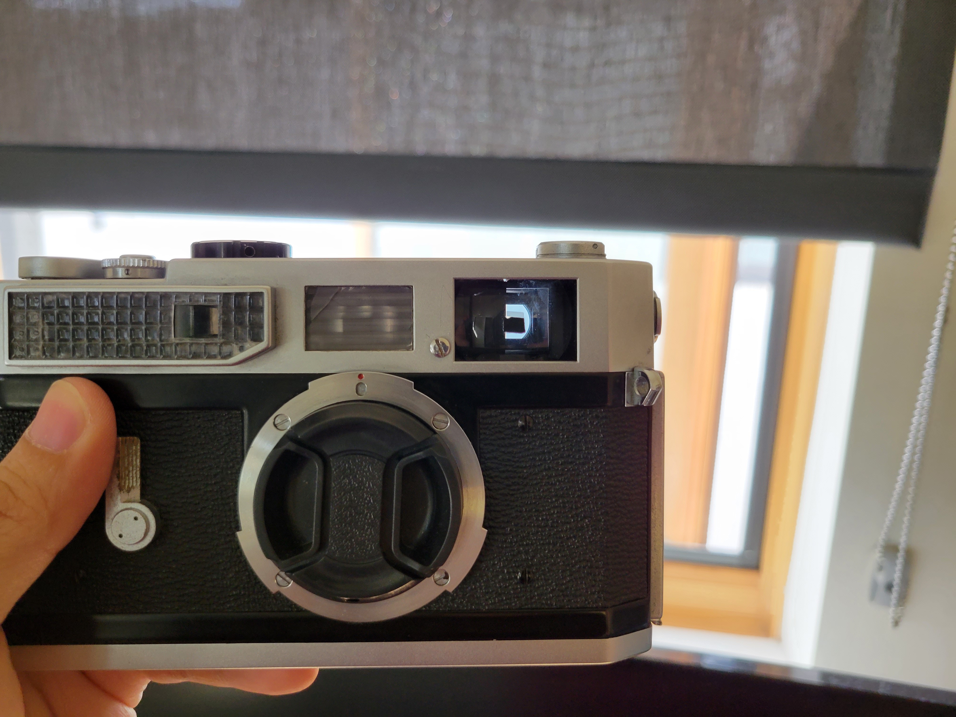
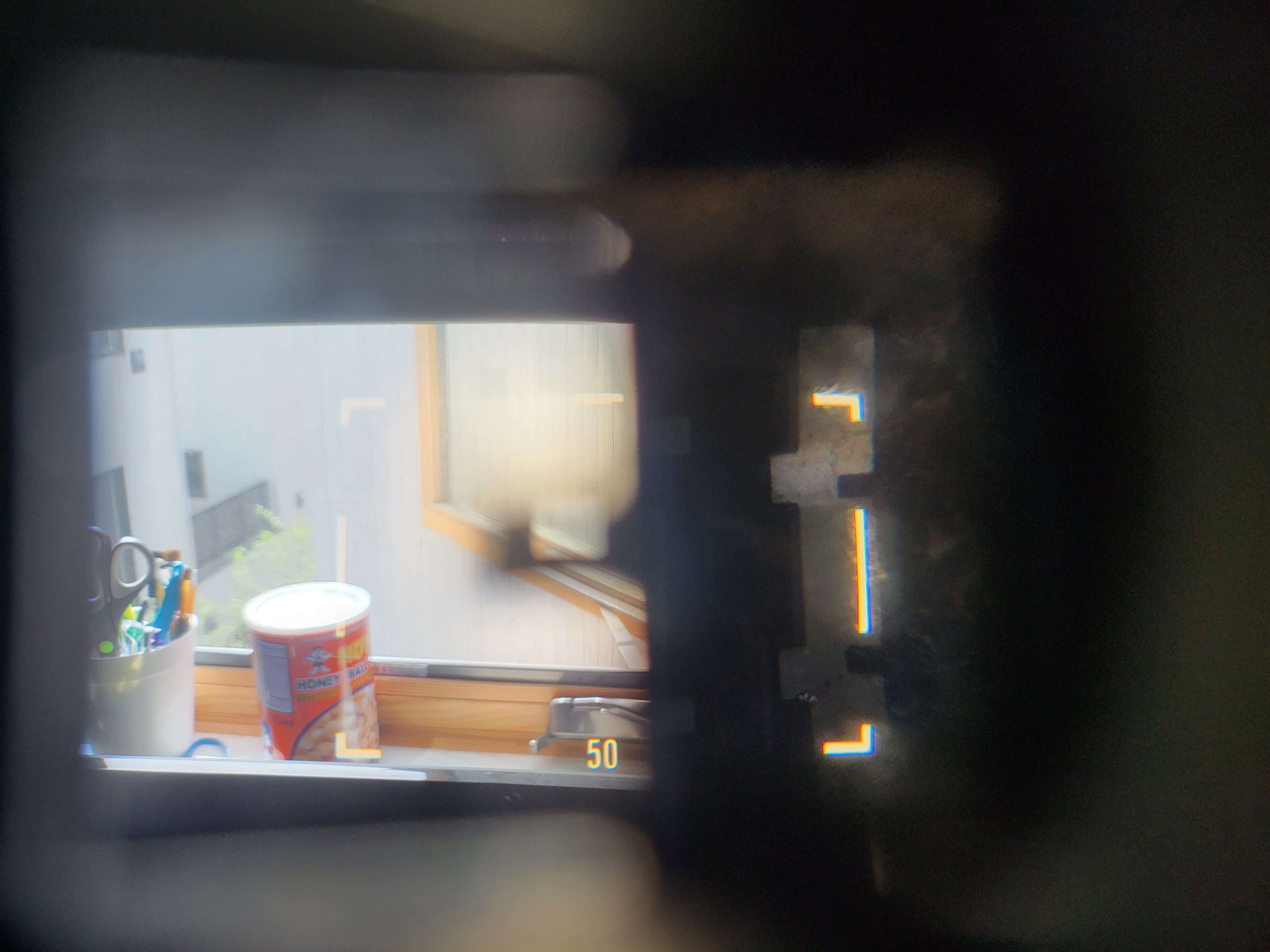
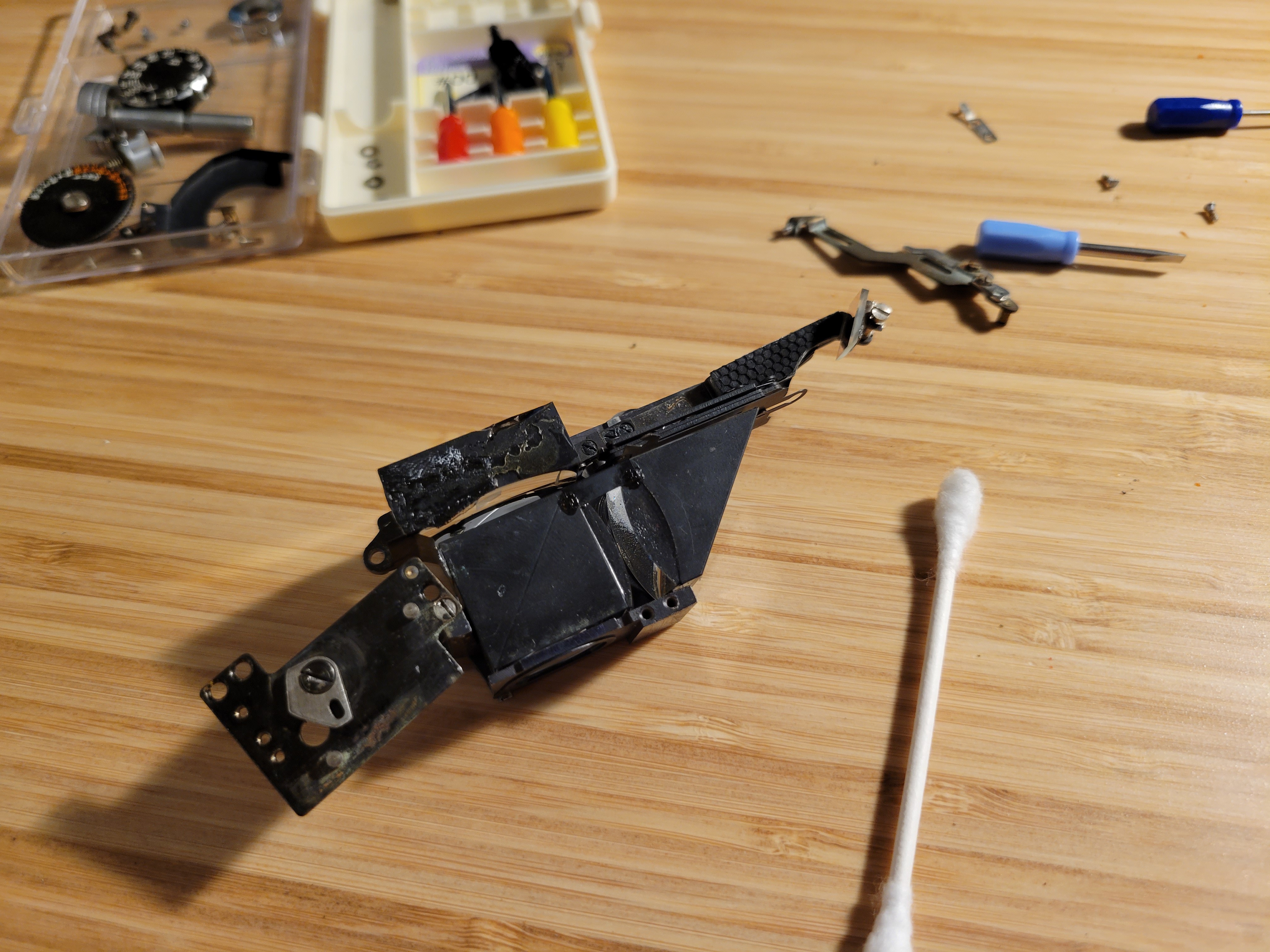
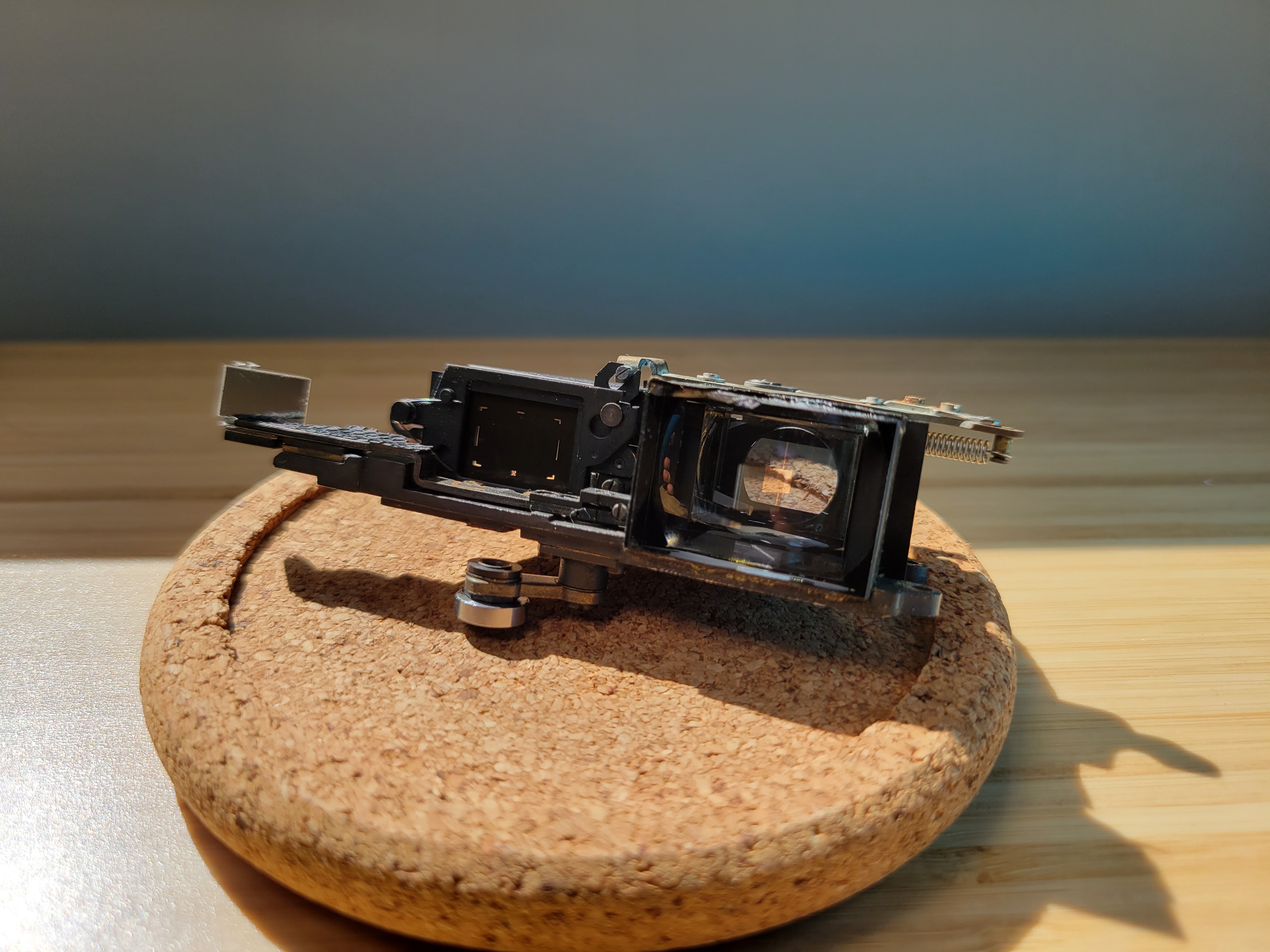
- The viewfinder/rangefinder optics comprise a single self-contained module. This makes it exceedingly easy to work with without fears of screwing up the optical alignment.
- Why the Sony NEX-5? Again, a few reasons:
- They are cheap - used examples can be found around $100, sometimes less.
- They are simple inside - Sony made this camera extremely easy to disassemble, by modern standards.
- This camera has been used for film-to-digital camera conversions before, so I don't have to tread through unknown territory. It's been done before, and people like Oliver (maker of the Frankencameras) have done a great job of documenting their work.
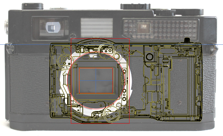
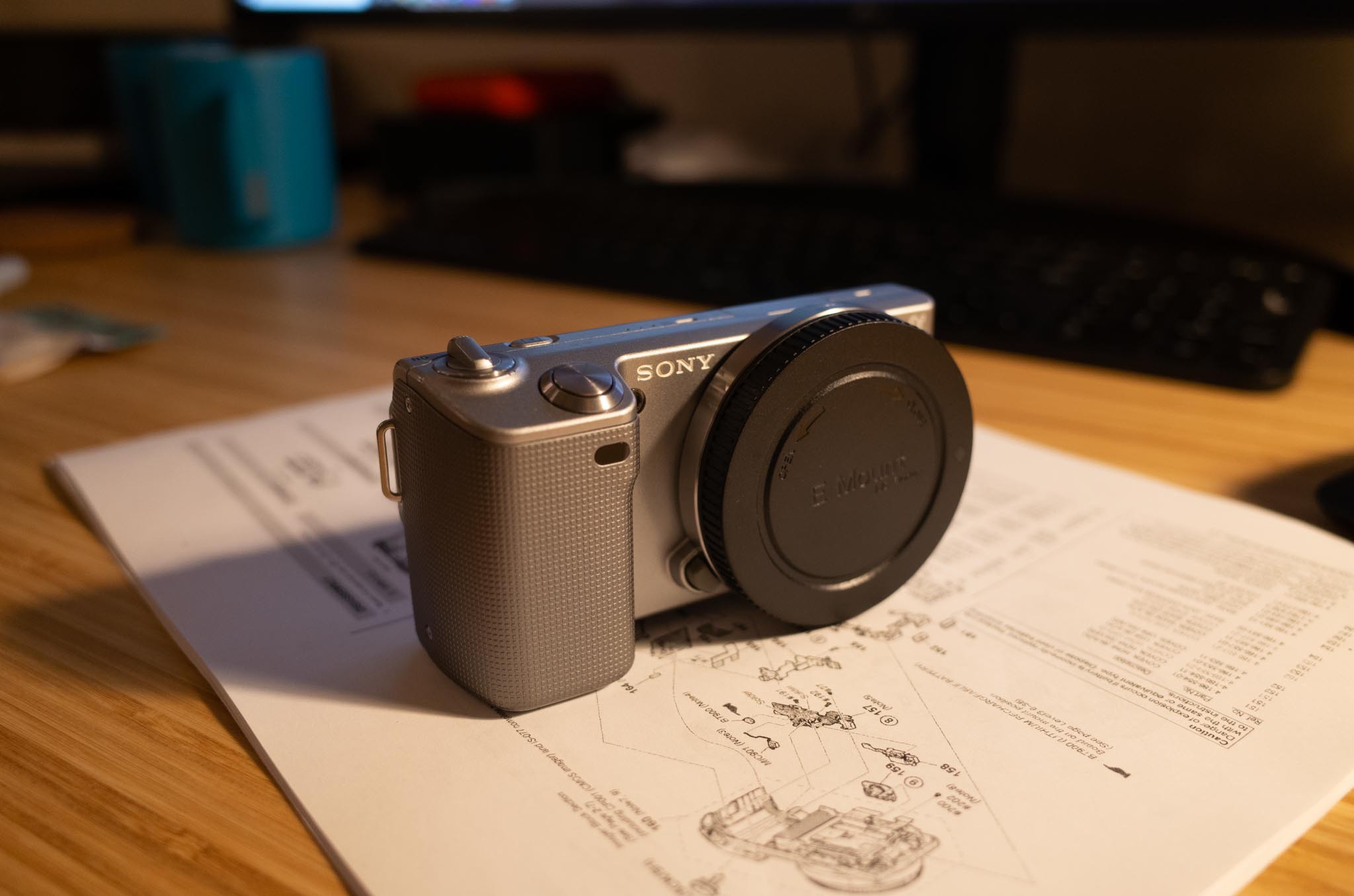
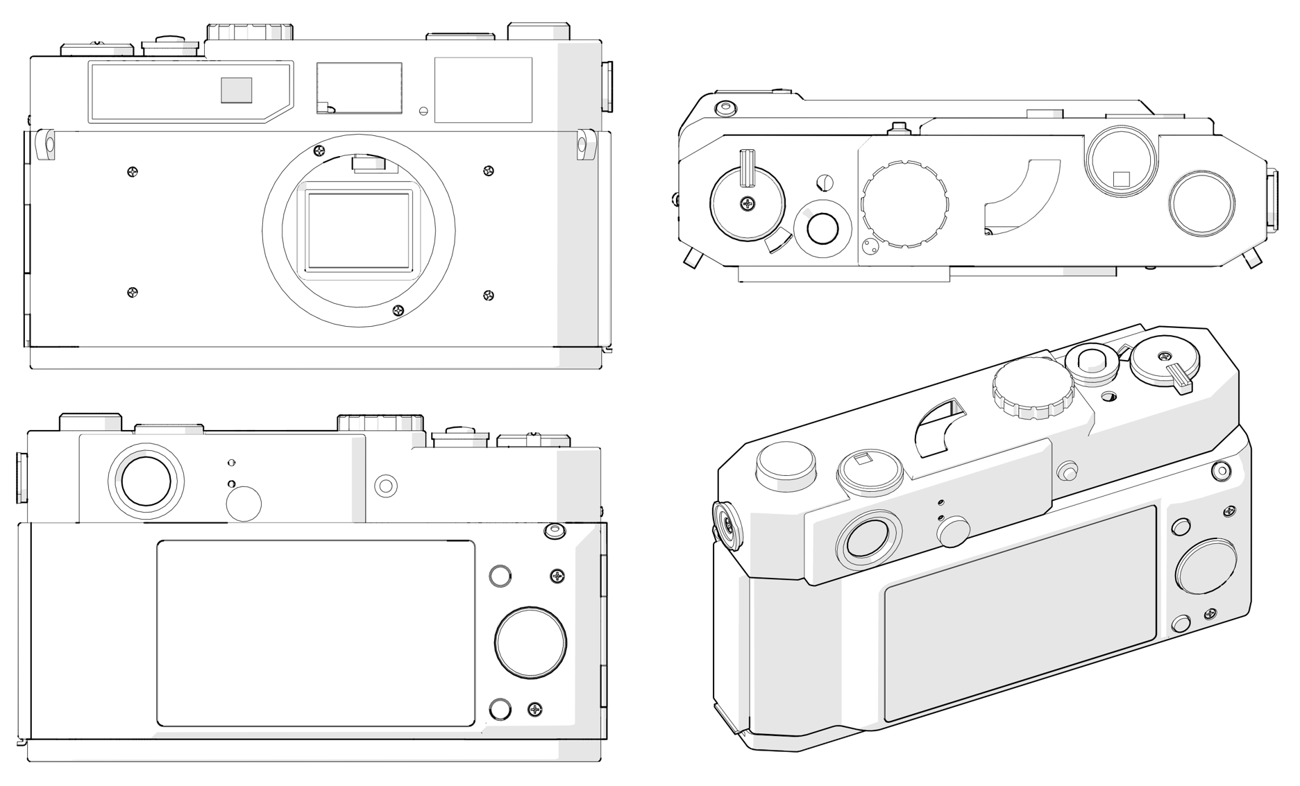
Based on others' work, I was feeling pretty confident that shoehorning this would work out. But still, I did a bit of research before buying parts. Repair manuals for both the Canon 7 and NEX-5 are available online (and free, with a little Googling) and are great resources for figuring out how things fit together. The NEX-5 also has vector drawings of the camera in various states of disassembly, which appear to be true to scale - which I used to make some mockups. Both the NEX and 7 are very prolific cameras, so there is an abundance of repair walkthroughs and teardowns showing off their guts - all good fuel for the imagination when considering how things will fit together.
I happened upon a 7 and an NEX-5 on eBay for $65 and $80, respectively. Both were in pretty well-used condition, and the 7 had recently undergone some surgery to fix a dislodged beamsplitter for the framelines... which immediately undid itself during transit. So, I had the opportunity to get familiar with the optical layout of the 7. Nothing a well-placed dab or two of super glue couldn't fix.
Anyway, it's been about a month since receiving the cameras, and they've been thoroughly hacked apart, measured, and modeled up in Solidworks. From the front, it looks pretty much like a Canon 7. Working around to the back, well, it looks a lot like a NEX-5 was grafted to the back - what, with the layout of the screens and the buttons, and all.
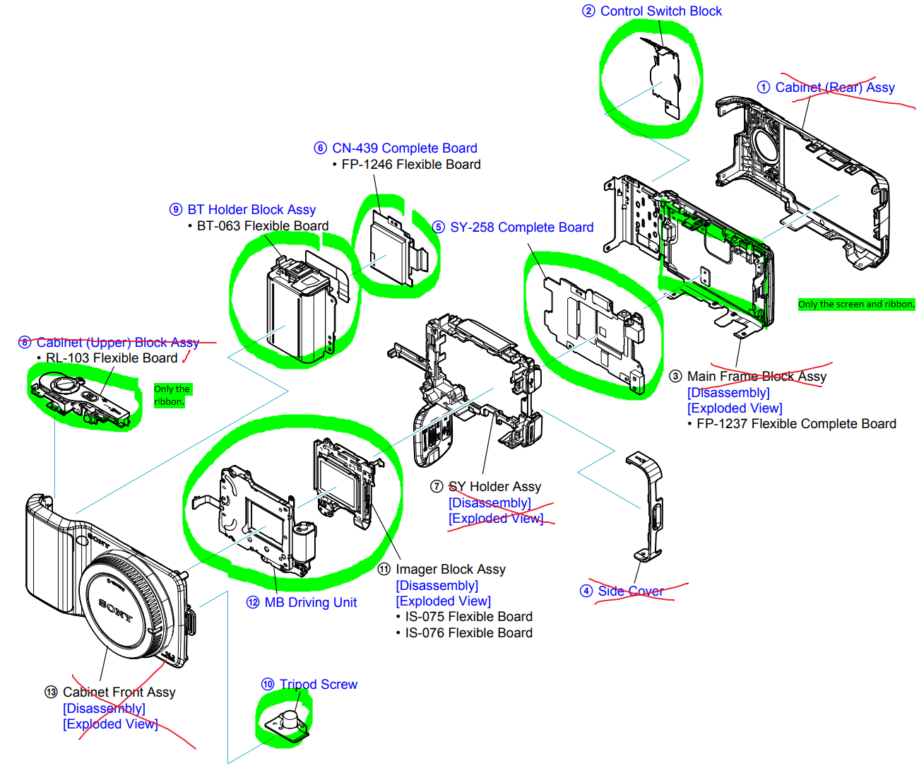
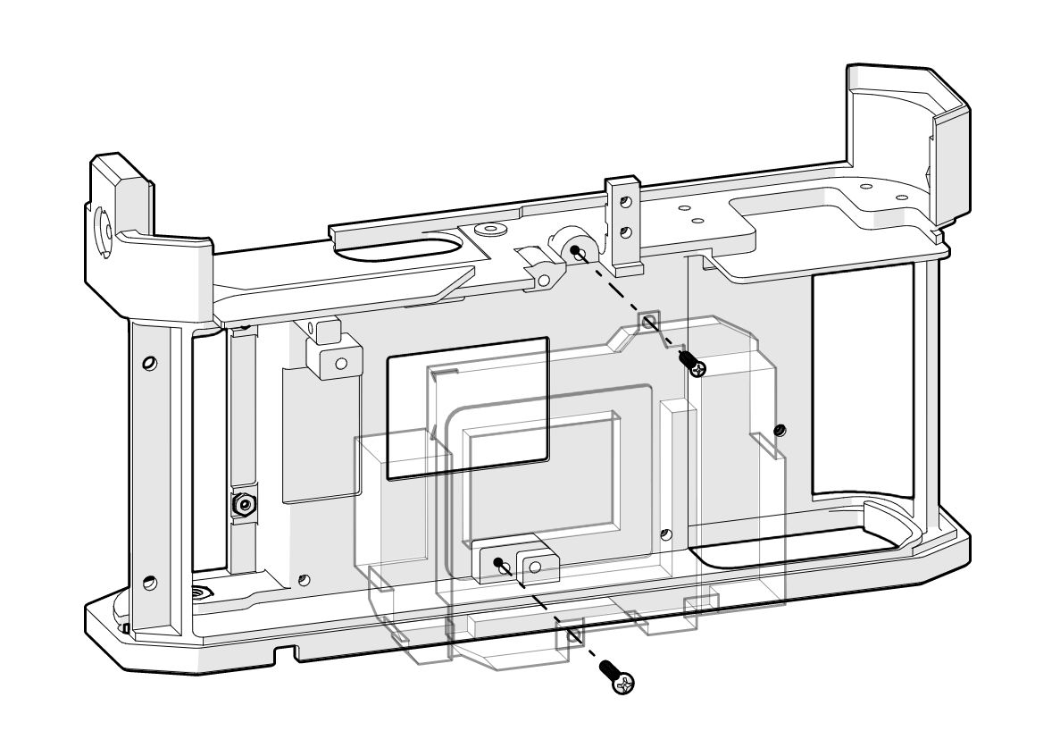
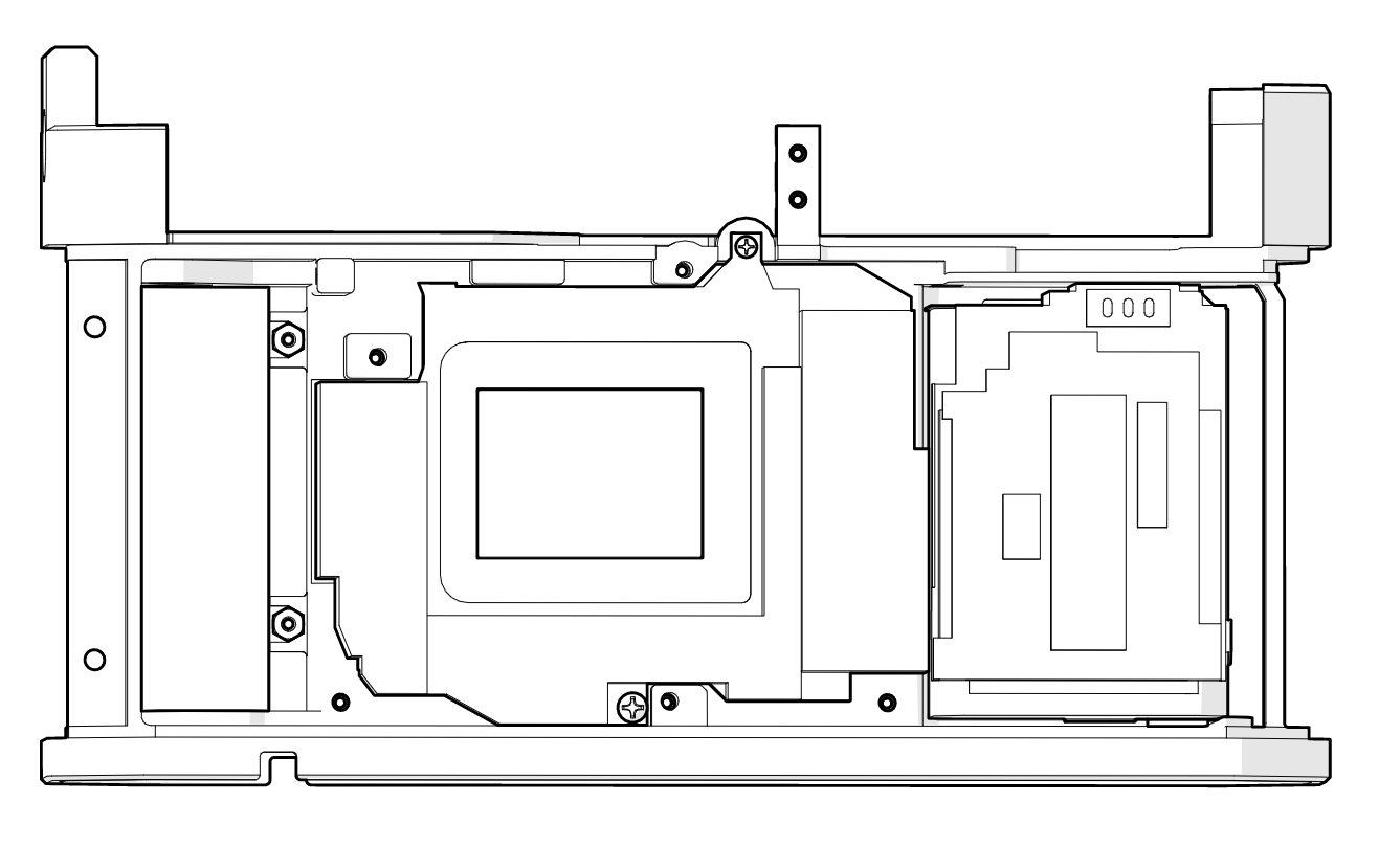
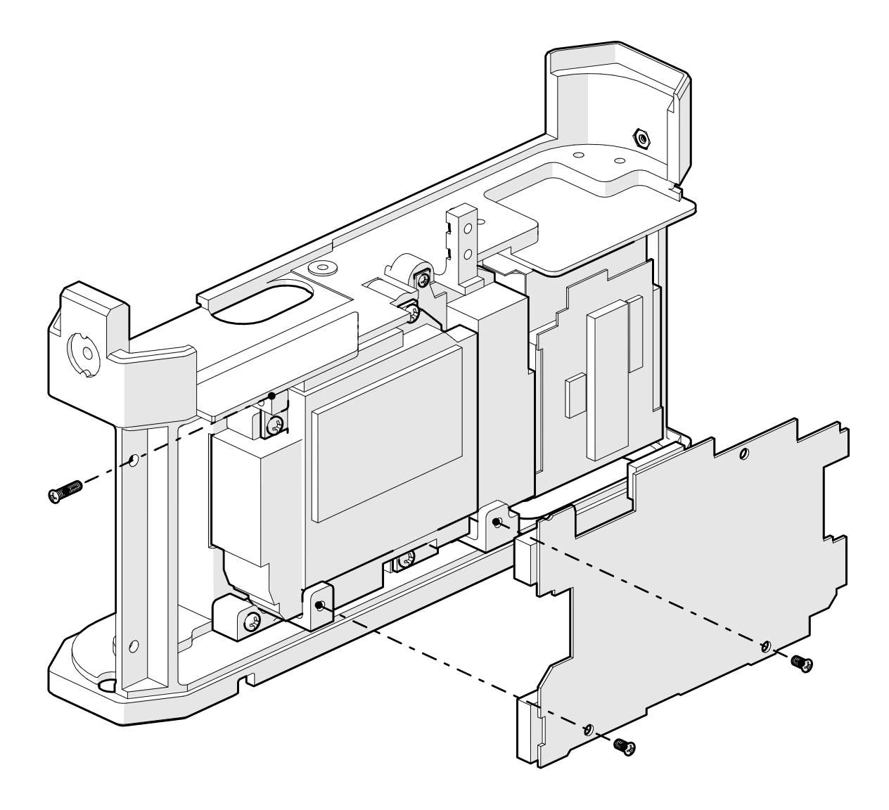
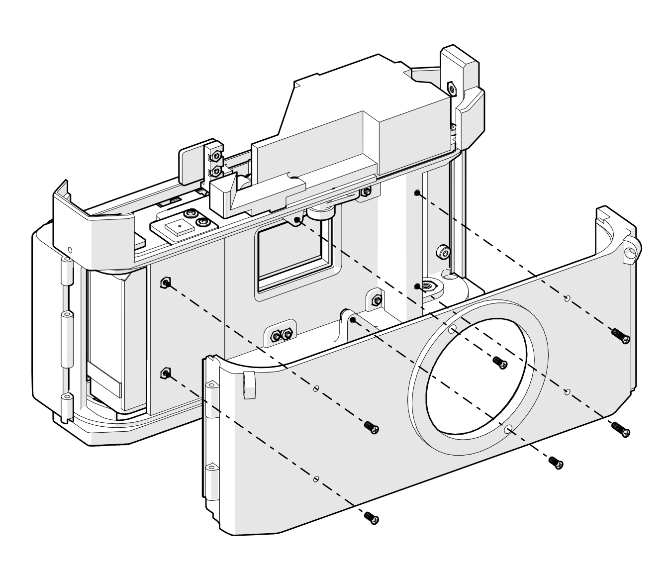
With the exception of the rangefinder/viewfinder unit, most of the Canon 7's internals end up in the scrap heap. A brand new chassis has been designed to accommodate the NEX's entrails. Here's my best IKEA imitation showing how the various parts fit together:
1. The shutter unit (transparent in the below image) is mounted to the chassis with some tiny machine screws.
2. The battery "cage" and SD card unit are fixed to the chassis using double-sided adhesive.
3. The image sensor sits atop the sensor, fixed to the chassis via more tiny machine screws.
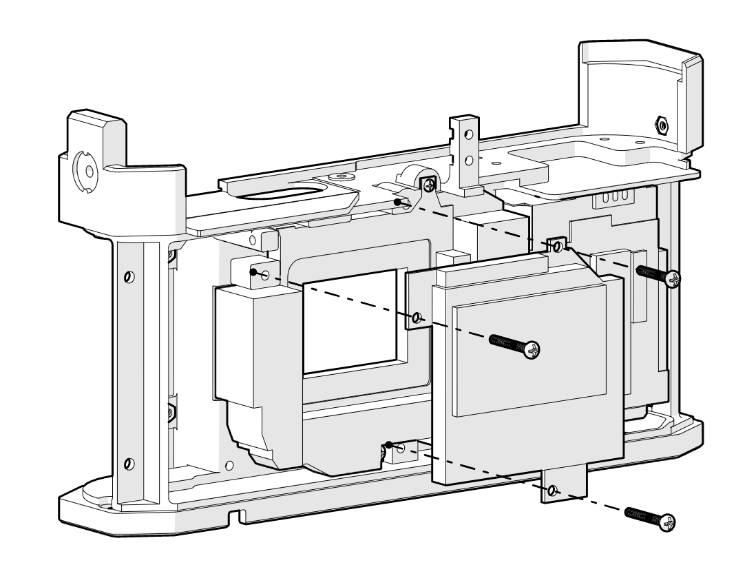
4. Standoffs provide an attachment point between the chassis and the motherboard.
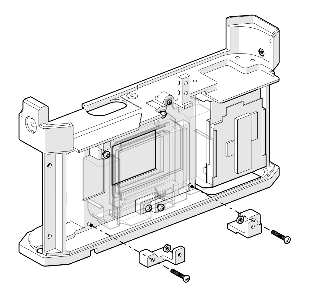
5. The motherboard is mounted to the standoffs.
 6. The NEX top control panel ribbon is fixed to the chassis using double sided tape. Breakout boards are mounted above the original ribbon and connected via tiny 38 AWG flying wires. The 3 PCBs basically just reposition the playback button (bottom), shutter button (center), and power switch (right). The point of relocating these buttons is to position them with access points in the Canon 7 top shell.
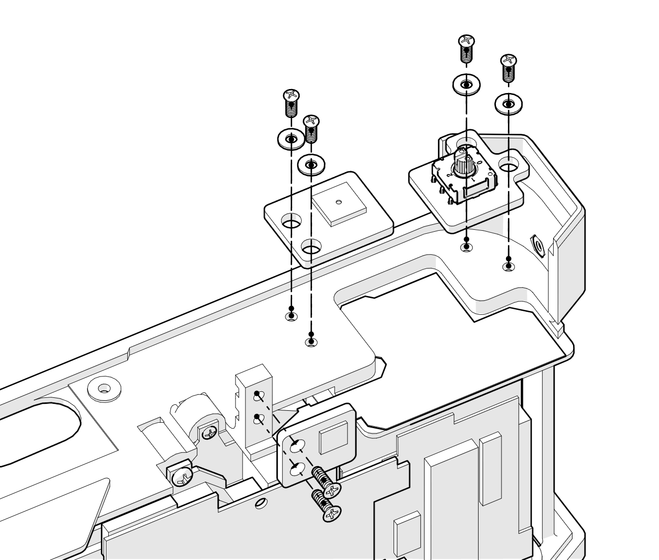
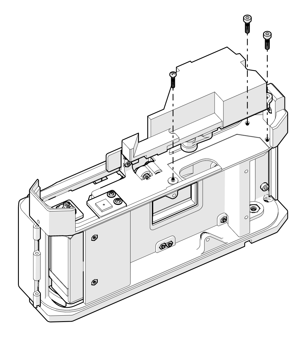
7. The NEX rear control panel sits above the battery cage and SD module.
8. The rear shell encloses the rear of the camera and holds the LCD display in place.

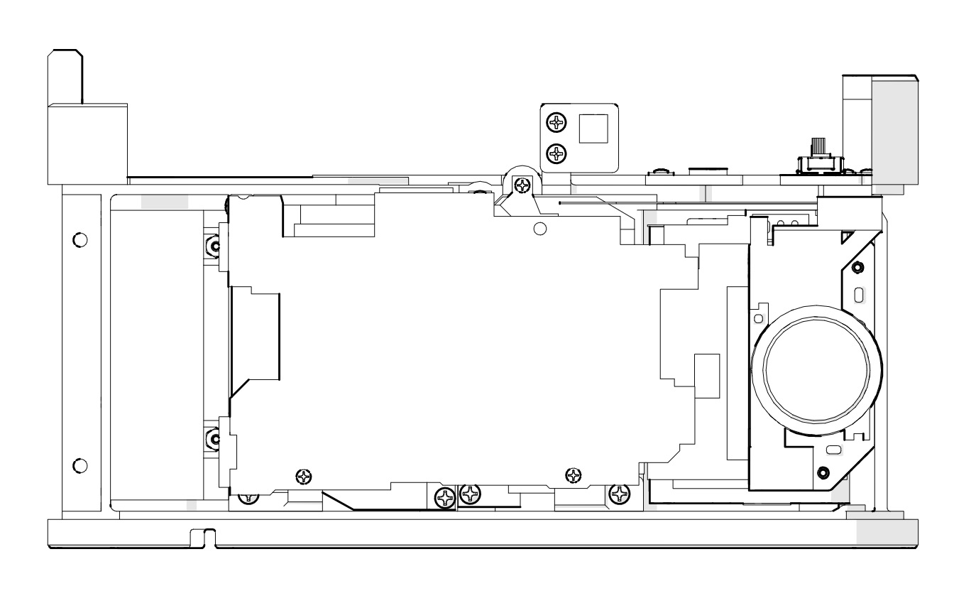
9. The RF/VF unit is affixed to the chassis, and the rangefinder cam slips through a slot into the exposure changer.
10. The original front shell from the Canon 7 is affixed to the main chassis with another myriad of tiny machine screws.
11. The original bottom shell from the Canon 7 is secured to the bottom shell using an extra-wide slotted flange screw (right) which can be removed with a suitably sized coin. The right side is secured with two extra-strong neodymium magnets. The hole on the left which would usually provide access to the tripod mount has been covered with a panel cover - no tripod mount on this camera! Just hold the camera really still. It's that simple.
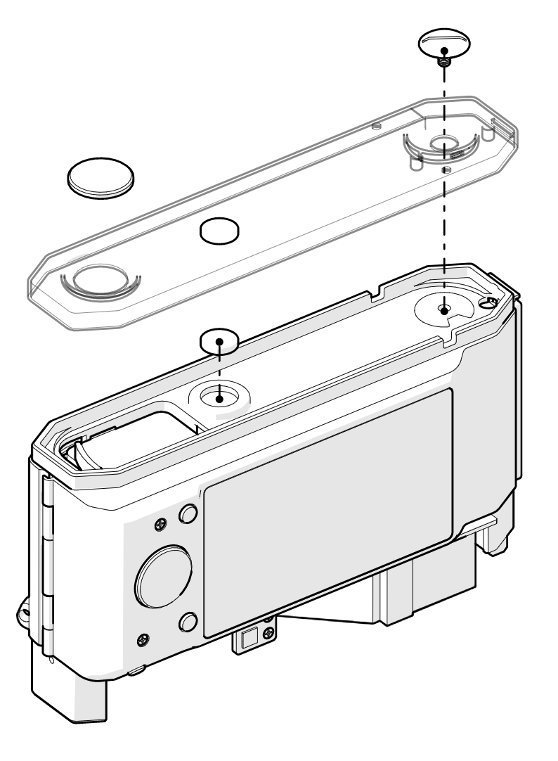
12. The top plate is carried over from the Canon 7, but a bunch of original components are used for the power switch (left), which replaces the film winder, and the shutter button (second from left).
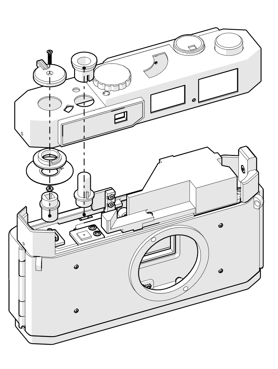
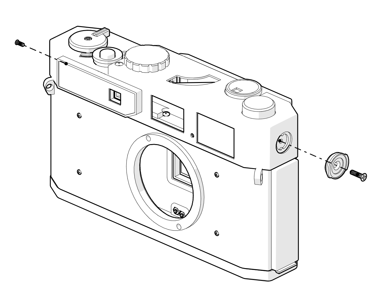
13. Finally, the top shell is secured by a couple of screws and a replica of the original flash bayonet.
All of the various parts and pieces have been ordered and should arrive later this week or early next week. I'm excited to get started and share progress!
Discussions
Become a Hackaday.io Member
Create an account to leave a comment. Already have an account? Log In.