 Jason Coon
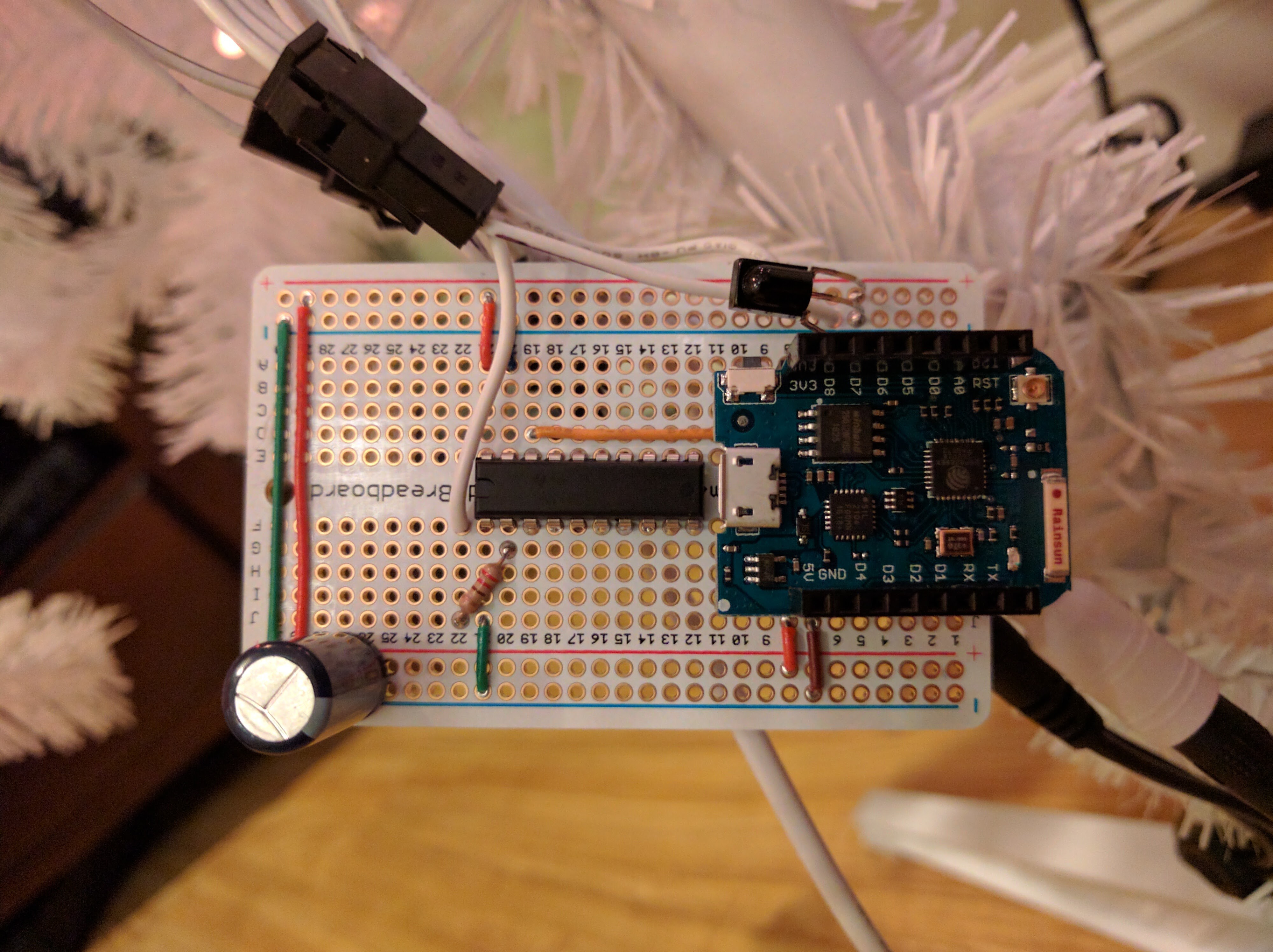
Controller Board
The data out of the first string is connected to the data in of the next. I cut the wires and added JST-SM connectors and extension wires between each section of the tree for easy disassembly, and between each level of branches since the regular wire spacing isn’t long enough.
I’m injecting power at the start and end of the string, and then at two different points in the middle.
The 5.5 x 2.5mm connectors are not rated for current this high, so I never run at full brightness, solid white. I’ve limited the max power in the firmware, and I’m planning to replace them with XT60 connectors as soon as they come in.
Assembly
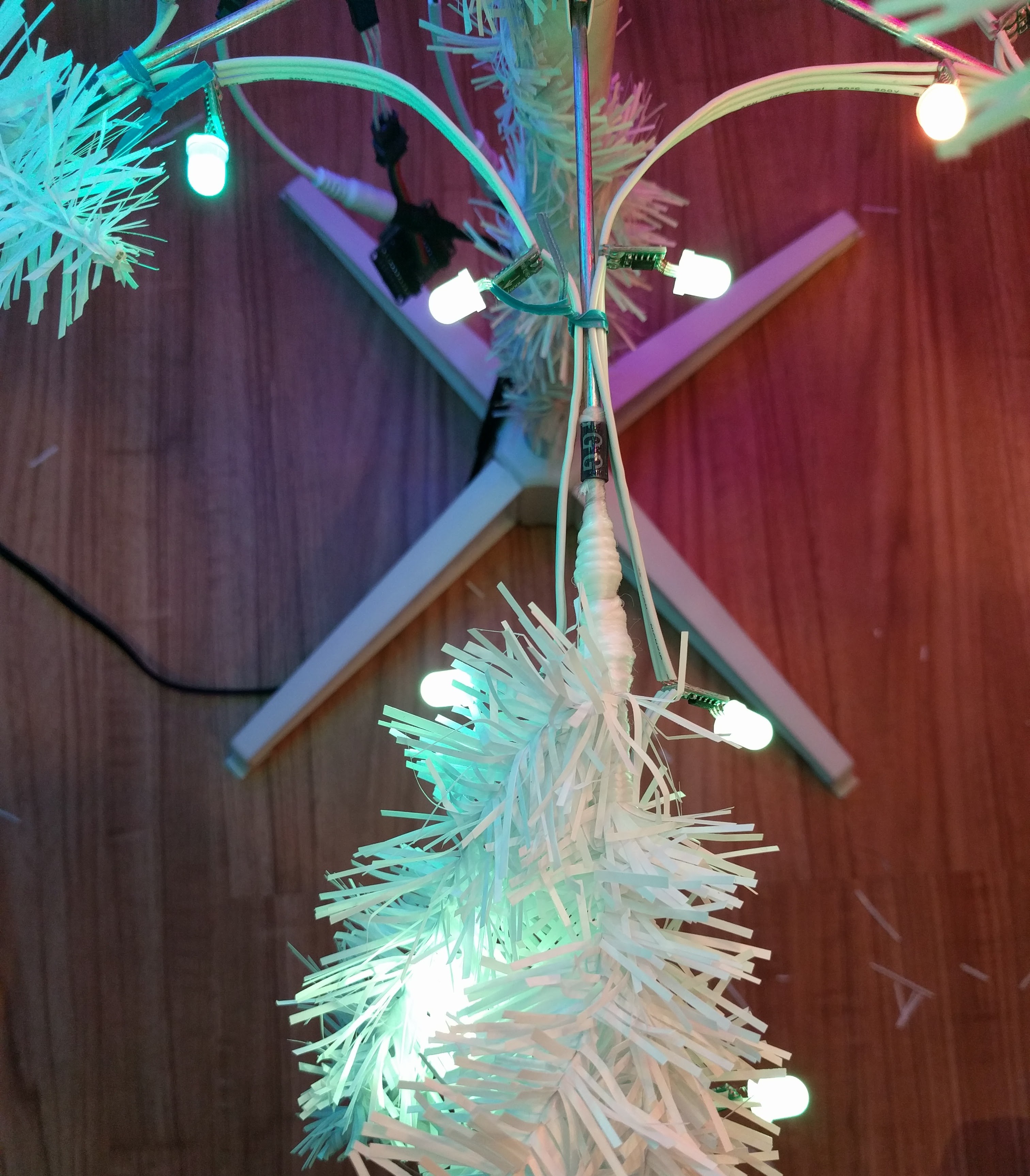
I assembled the tree, and then loosely attached the LEDs with twist ties while I worked out the way I wanted to run them. Once I had the positions finalized, I replaced the twist ties with 4” zip ties. I used the zip ties liberally, making sure to reduce wire strain wherever possible.
I ended up using 6 LEDs per branch. The first 6 rows/levels have 6 branches each.
Layout
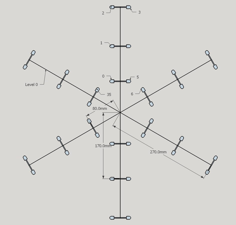
Level 0
I started the LED string (LED 0) on the bottom row of branches near the center of the tree. I worked my way way along the branch outward, clockwise to the other side of the branch, and back inwards towards the center. LED 6 starts at the same position as LED 0, on the next branch clockwise.
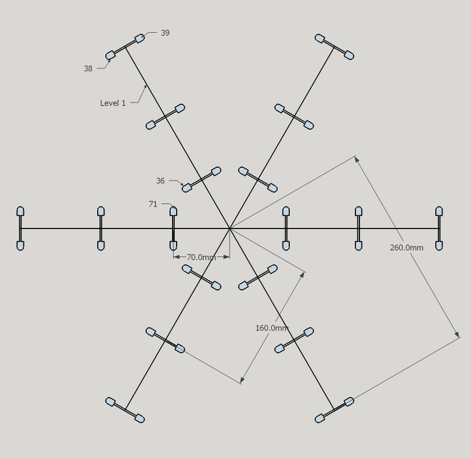
 Level 1
The wires between LED 35 (on level 0) and LED 36 (on level 1) weren't long enough to make the jump between branch levels. I cut the wires in the center and added JST-SM connectors on both ends (male on one end and female on the other). The connectors snap into a protective black plastic housing. I did the same between every level of branches.
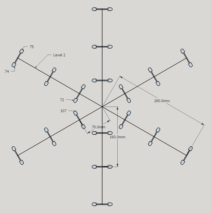
 Level 2
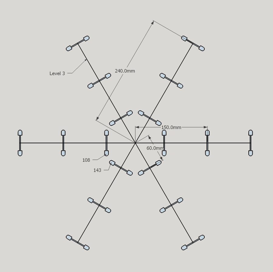
 Level 3
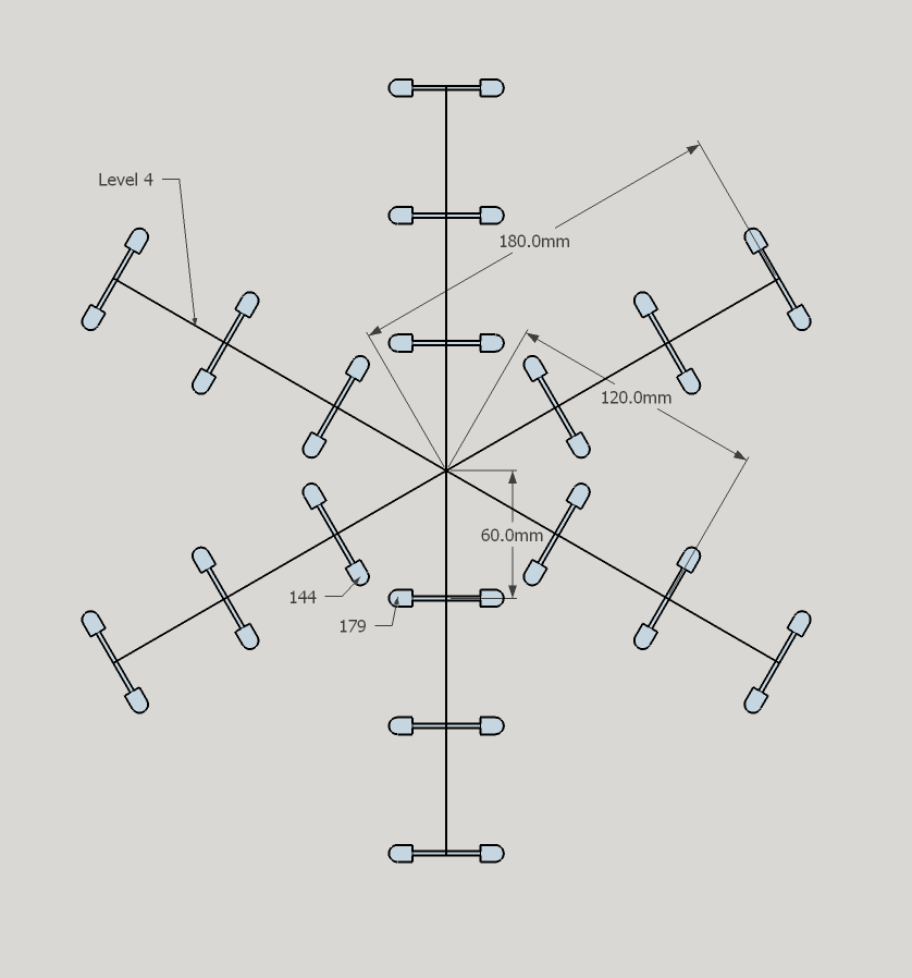
 Level 4
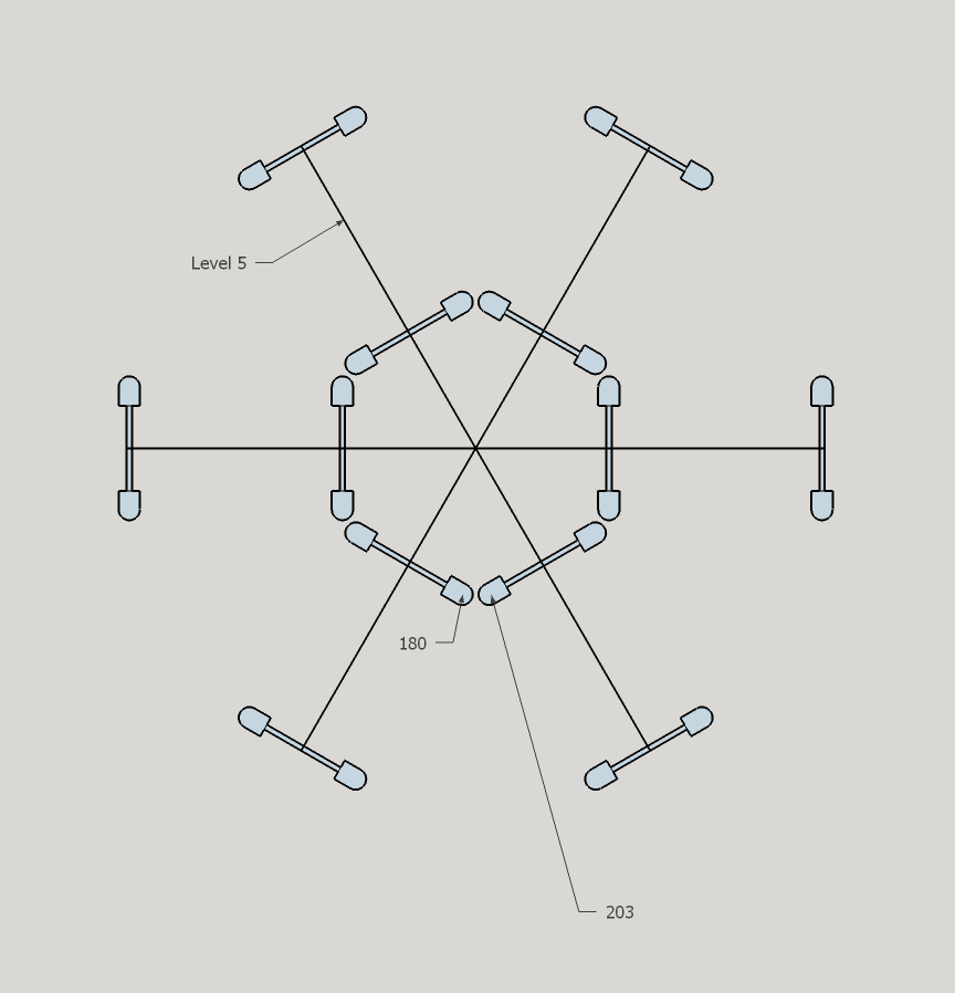
 Level 5
The branches on this level are shorter, so I just ran four LEDs per branch.
 Level 6
The top section of the tree is less organized, and I struggled to attach the LEDs at regular spacing.
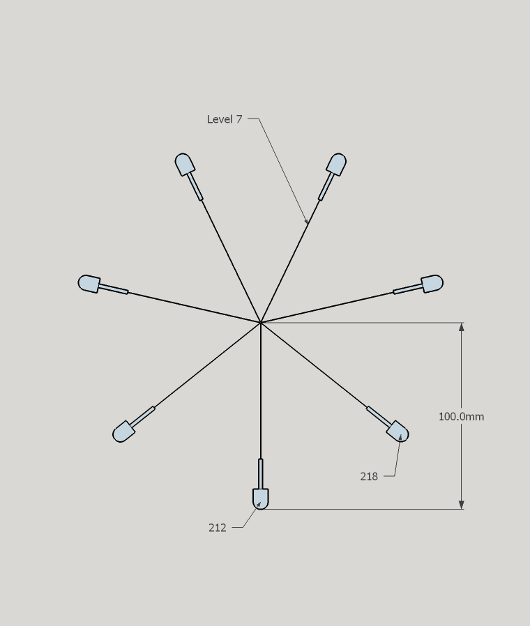
 Level 7
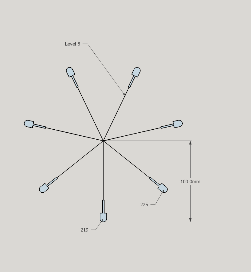
Levels 7 & 8 are identical.
 Level 8
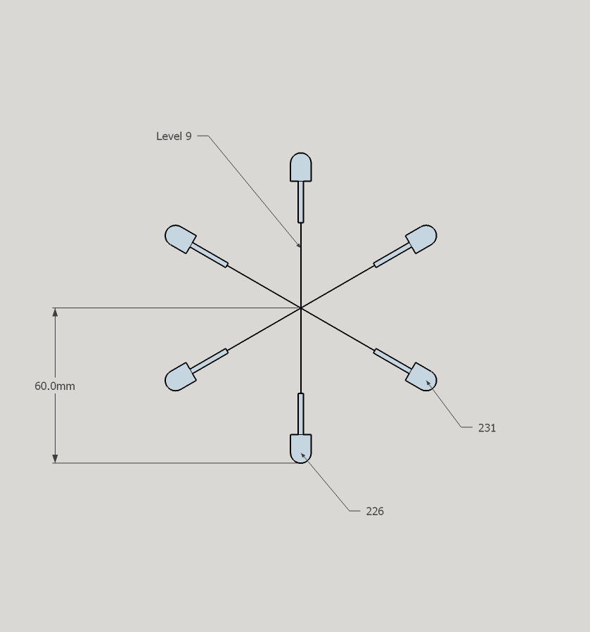
 Level 9
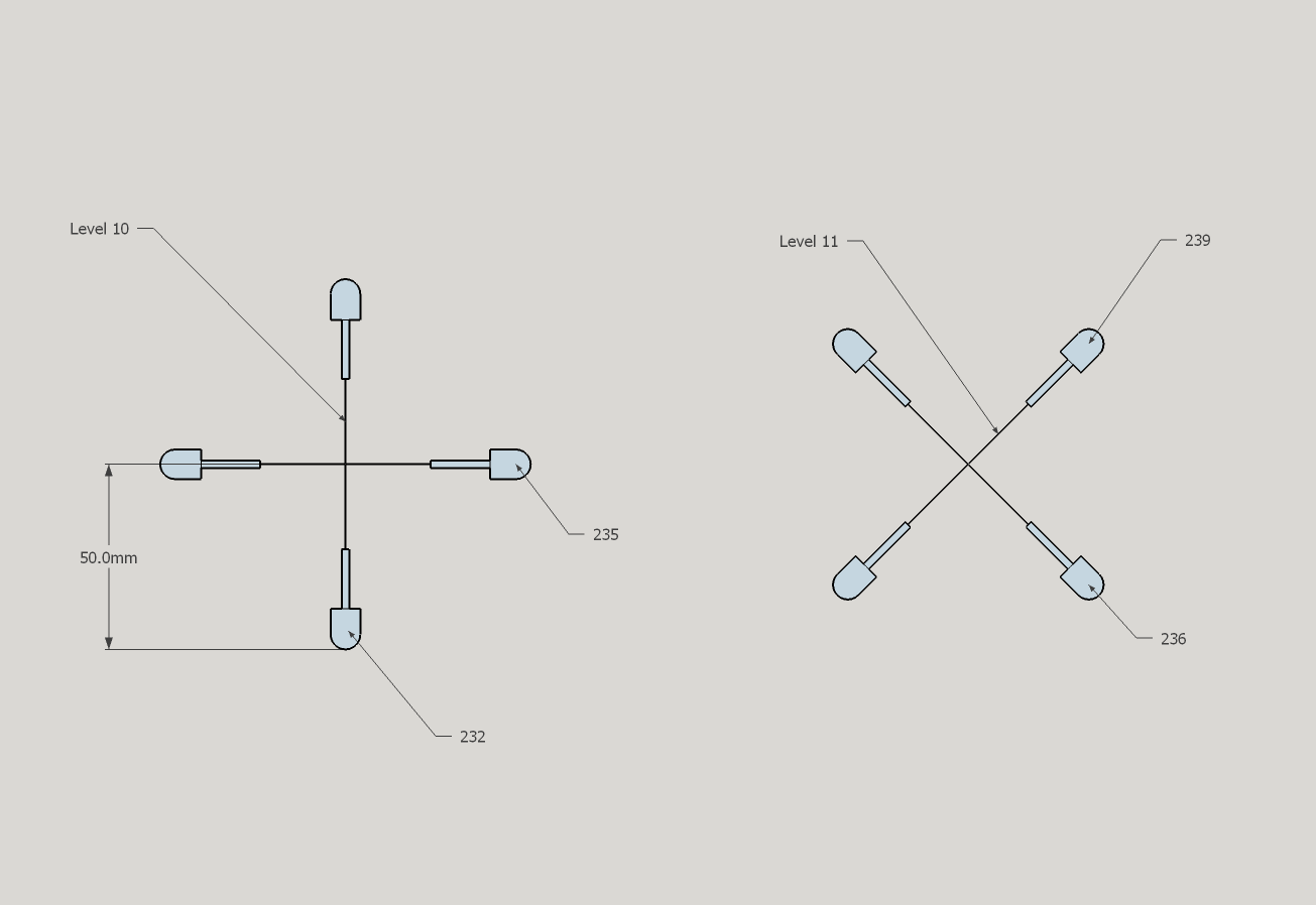
 Levels 10 & 11
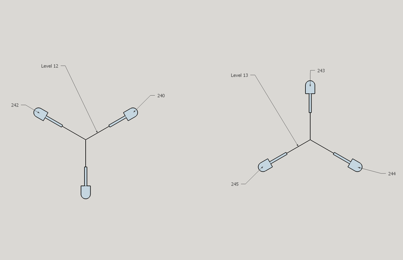
 Levels 12 & 13
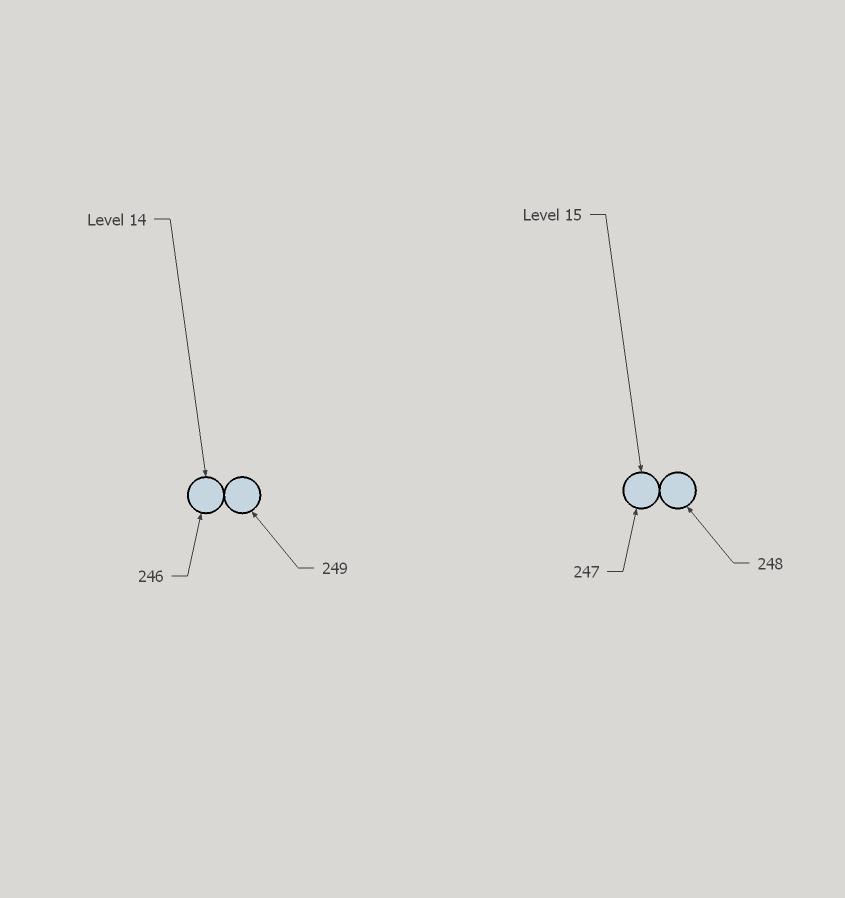
 Levels 14 & 15
I ran the remaining four LEDs up the left side of the vertical top branch, then back down the right side.
 Mapping
With the layout finalized, I went about the process of mapping this thing. While I could run animations treating the tree as a single long spiral strand of LEDs, I wanted to be able to scroll vertically, horizontally, radially (inwards and outwards), rotate clockwise, etc.
I used a Google Sheet (https://docs.google.com/spreadsheets/d/1ib-8P9rvbIDgRNVO_Omekv3-u5b-ewHhnlkTtL8K9bk/edit?usp=sharing) to keep track of my measurements, and to map them to different numerical spaces. For example, I measured height and radius in centimeters, but then wanted to map them to single byte values (0-255) to save program space and allow easier animation.
Z Axis
To run patterns uniformly up and down the tree, I needed a map of the LEDs in the Z axis. Starting at the bottom branch as zero, I measured the height of each branch. I measured approximately 0, 6, 12, 19, 26, 32, 36, 39, 42, 44, 46, 48, 50, 53, 56 and 59cm. Since I already recorded how many LEDs are on each level, it’s an easy matter to record the Z position of every LED.
Angle
To animate patterns that rotate around the tree, I need the angle of every LED. I started with the first branch as 0 degrees. For simplicity, I treated every LED on the same branch as having the same angle, although technically they differ by a few degrees from one side to the other. I drew a diagram of each level, noting the start and end LED indices and positions. From this, I was able to record the angle of each LED in the sheet. I recorded them in degrees, converted them in the sheet to one byte range values, and to radians (needed for XY mapping). Level 0 branches were at 0, 60, 120, 180, 240, and 300 degrees. Converted to one byte range values, that’s approximately 0, 43, 85, 128, 171, and 213. Level 1 branches are offset by -30 degrees from level 0: 330, 30, 90, 150, 210, and 270 degrees. I repeated this for every level.
Radius
Knowing the radius of every LED will not only allow me to run animations inward and outward, but also allow me to calculate the X and Y position of the LEDs, using the previously recorded angle and a little trigonometry. I measured the radius of each ring of LEDs on each level. Each LED in the ring is fairly equal distance from the center, so I only measured one, or took the average if there was any significant difference. The radii are noted in the diagrams above. I recorded the radii in the sheet.
X and Y Axes
The X coordinate for an LED can be calculated with its radius (r) and angle in radians (a):
x = r * sin(a)
y = r * cos(a)
Web App
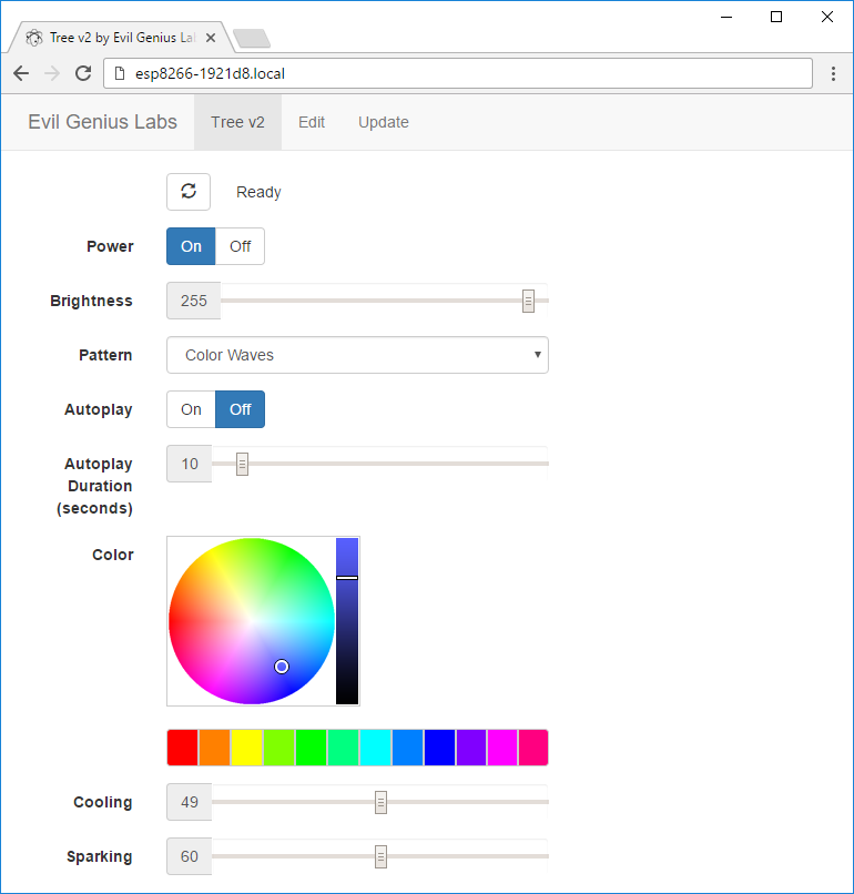 Patterns are requested by the app from the ESP8266, so as new patterns are added, they’re automatically listed in the app.
The web app is stored in SPIFFS (on-board flash memory).
The web app is a single page app with separate files for js and css, using jQuery (https://jquery.com) and Bootstrap (http://getbootstrap.com). It has buttons for On/Off, a slider for brightness, a pattern selector, and a color picker, using jQuery MiniColors(http://labs.abeautifulsite.net/jquery-minicolors). Event handlers for the controls are wired up, so you don’t have to click a ‘Send’ button after making changes. The brightness slider and the color picker use a delayed event handler, to prevent from flooding the ESP8266 web server with too many requests too quickly.
Compiling
Follow the instructions on the following pages to install the required software for your OS (Windows, Linux, Mac):
- Install Arduino
- Install Arduino core for ESP8266
Download and install the following libraries, using the instructions here: https://www.arduino.cc/en/Guide/Libraries
- FastLED (https://github.com/FastLED/FastLED)
- WebSocket Server and Client for Arduino (https://github.com/Links2004/arduinoWebSockets)
- IRremote ESP8266 Library (https://github.com/sebastienwarin/IRremoteESP8266)
Download the source code here: https://github.com/evilgeniuslabs/tree-v2
In Arduino, choose the following options from the Tools menu:
- Board: WeMos D1 R2 & mini
- Flash Size: 4M (3M SPIFFS)
- CPU Frequency: 160MHz
- Upload Speed: 921600
Select the correct port for your board (it’s easiest to unplug any other USB serial devices).
Finally, click the Upload button.
Please report any errors, problems, questions, etc to the Issue Tracker: https://github.com/evilgeniuslabs/tree-v2/issues
SPIFFS (SPI Flash File System)
The web app needs to be uploaded to the ESP8266’s SPIFFS. You can do this within the Arduino IDE after installing the Arduino ESP8266FS tool: https://github.com/esp8266/Arduino/blob/master/doc/filesystem.md
With ESP8266FS installed run the sketch and then upload the web app using the ESP8266 Sketch Data Upload command in the Arduino Tools menu.
Compression
The web app files can be gzip compressed before uploading to SPIFFS by running the following command:
zip -r data/
The ESP8266WebServer will automatically serve any .gz file. The file index.htm.gz will get served as index.htm, with the content-encoding header set to gzip, so the browser knows to decompress it. The ESP8266WebServer doesn’t seem to like the Glyphicon fonts gzipped, though, so I decompress them with this command:
gunzip -r data/fonts/
REST Web services
The firmware implements basic RESTful web services (https://en.wikipedia.org/wiki/Representational_state_transfer) using the ESP8266WebServer library. Current values are requested with HTTP GETs, and values are set with POSTs using query string parameters. It can run in connected or standalone access point modes.
Support
Please report any errors, problems, questions, etc to the Issue Tracker: https://github.com/evilgeniuslabs/tree-v2/issues