 Leszek Jakubowski
The display tube has 100 anodes (in the default mounting orientation going horizontally from left to right) and a 100 cathodes (going vertically from top to bottom). Whenever the voltage between an anode-cathode pair goes above 235V the pixel on their intersection begins to glow and is extinguished when the voltage goes below 100V (according to the lamp's datasheet).
See https://en.wikipedia.org/wiki/Neon_lamp for how the lamp works in more detail.
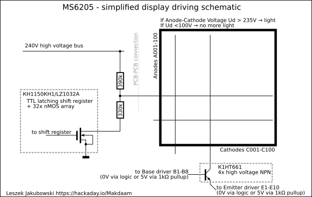
The anodes are pulled up constantly to 240V via 390kΩ resistors, and selectively pulled down via 330kΩ using the КН1150КН1 nMOS array (very similar to Sony LZ1032A). Each nMOS array has a TTL compatible shift register built in, which is filled with the data of the whole vertical line to be displayed. There are 2 groups on Anodes, so the loading of data is not as simple as clocking all bits in sequence, but I'll get to that later.
When it comes to the cathodes, only 80 out of the 100 are connected to the driving circuit. They're arranged in a groups of 5 driven, 1 not connected and additionally some not connected on the edges. Because the display was originally intended to only show 5x7 pixel characters the vertical lines between the letters weren't needed.
Maybe in the next version of the project I'll add driving circuits to the missing cathodes. It would be great if the wires are soldered to the PCB but if they're not I'm not going to risk breaking the neon tube when separating the epoxy glued PCB.
The cathode selection circuitry is much simpler there's an array of high volatage NPN transistors (packed 4 per IC) where the collector is connected to the cathode, the base and emitter are driven by TTL logic pull-downs and 1kΩ pull-ups to 5V on the Anode Driver PCB. Whenever the Base is pulled up to 5V and the Emitter is pulled down to 0V the cathode connected to the Collector is active.
The arrangement of the TTL decoders and not gates guarantees that there's at most 1 Base pulled up and at most 1 Emitter pulled down at the same time.
Discussions
Become a Hackaday.io Member
Create an account to leave a comment. Already have an account? Log In.