 Arya
AryaAaaaa hackaday editor won't allow photo uploads

Anyway, upload them in a private chatroom, then get image URL and link it here => perfection
So, first of all, *ahem*

Okay? You will burn your panel if you don't do that.
Now, let's see what's up.
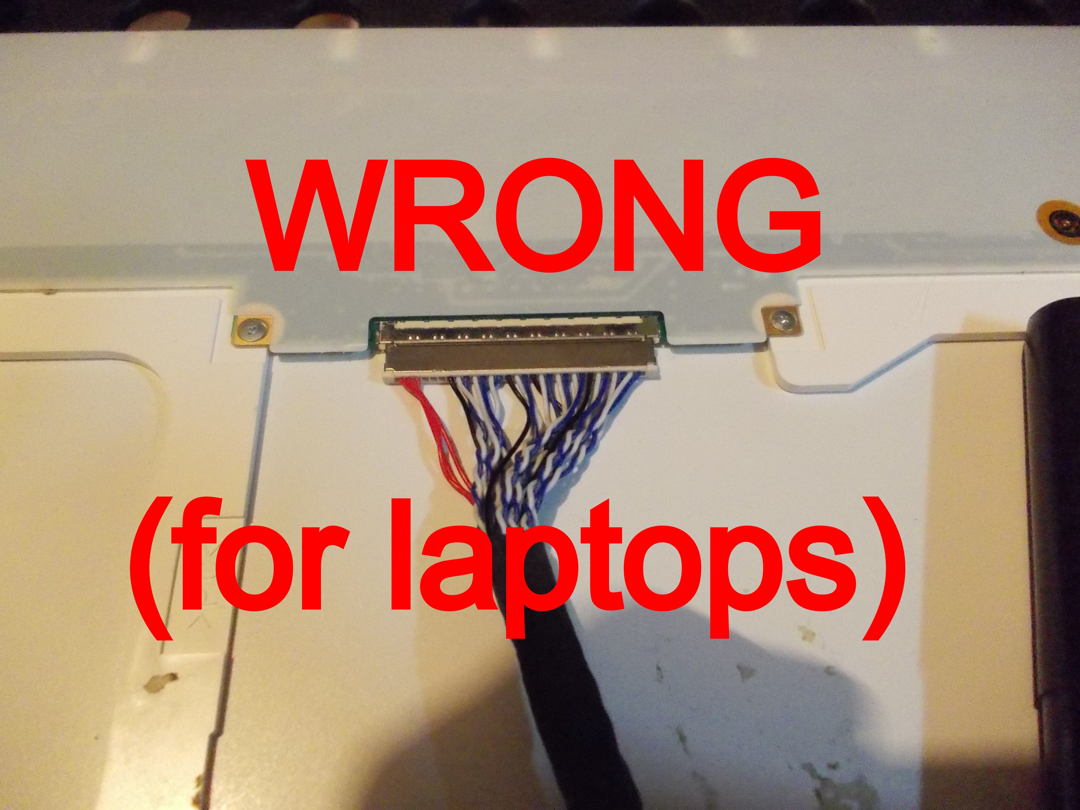
The default "MT6820" or "MT561" LVDS cable (that you get if you don't specifically buy this board listed as compatible with laptop screens) is not compatible with laptop panels! I've seen tons upon tons of angry messages on Aliexpress about how "the board didn't fit my laptop display", and hardly enough awareness of the problem - most people chuck the board in a drawer and never try again.
Two things you can do:
1) Buy a proper cable: FIX-30P-S6 , it will work as intended.
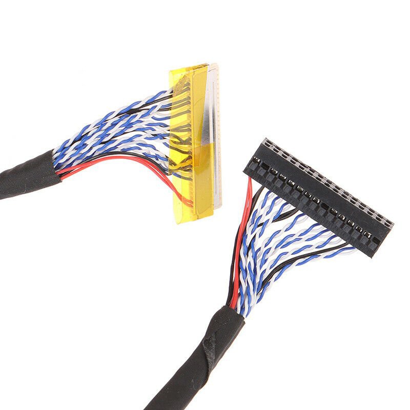
If you have a high-res panel, make sure the cable in the picture has as many wires as the cable in the store listing - a cable with only half of the blue&white wires would be called FIX-30P-D6, and while it might work for you if your display only uses half of the lanes (i.e. a 1280x800 display or a 1366x768 display), it won't work for higher-res displays.
For some reason, some sellers sell FIX-30P-S6 cables with "FIX-30P-D6" in the listing name - and vice-versa. In that case, you should go by whether there's "dual" mentioned in the listing name *and* on whether the photo is correct - if there's both a "dual" in the listing name and a photo shows a dual LVDS cable as pictured above, it should be safe to buy - or refund, in case that fails =D
What if you can't easily buy a replacement cable, though? Maybe you have budget constraints, maybe you need it urgently, or maybe you're miffed - after all, you already have a perfectly good cable, just that it's miswired!.
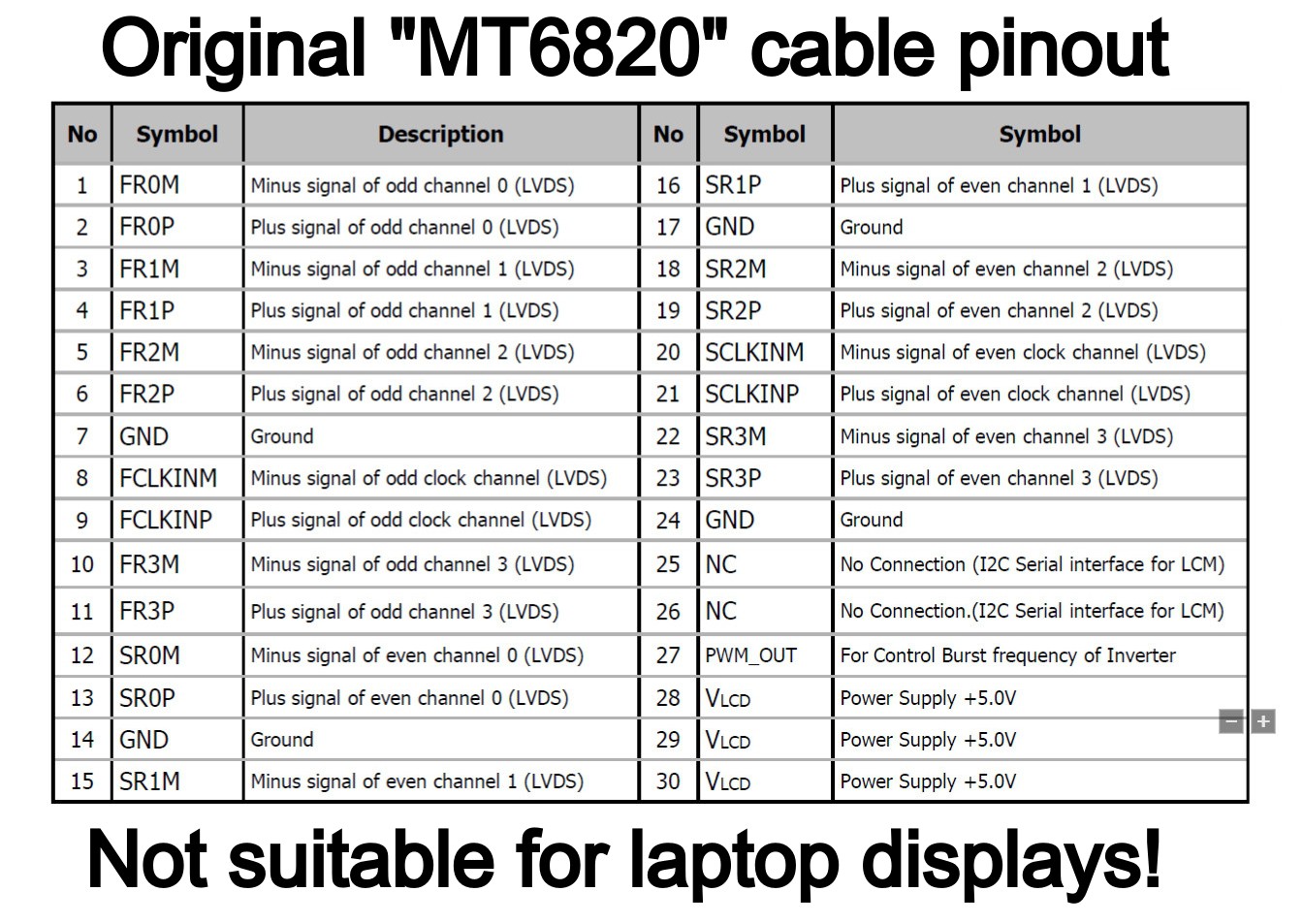
Here's the original cable pinout that you will get from the shop:
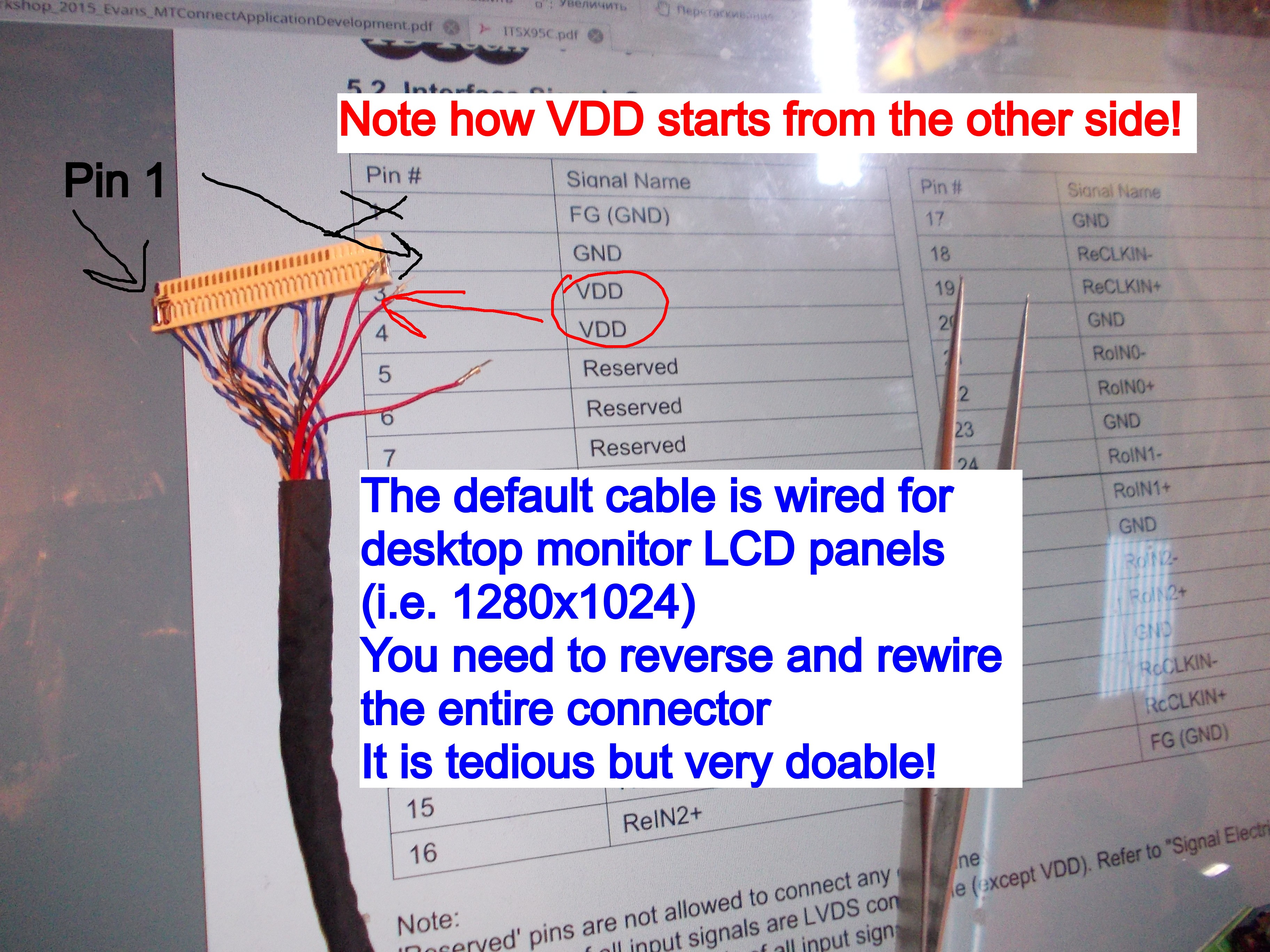
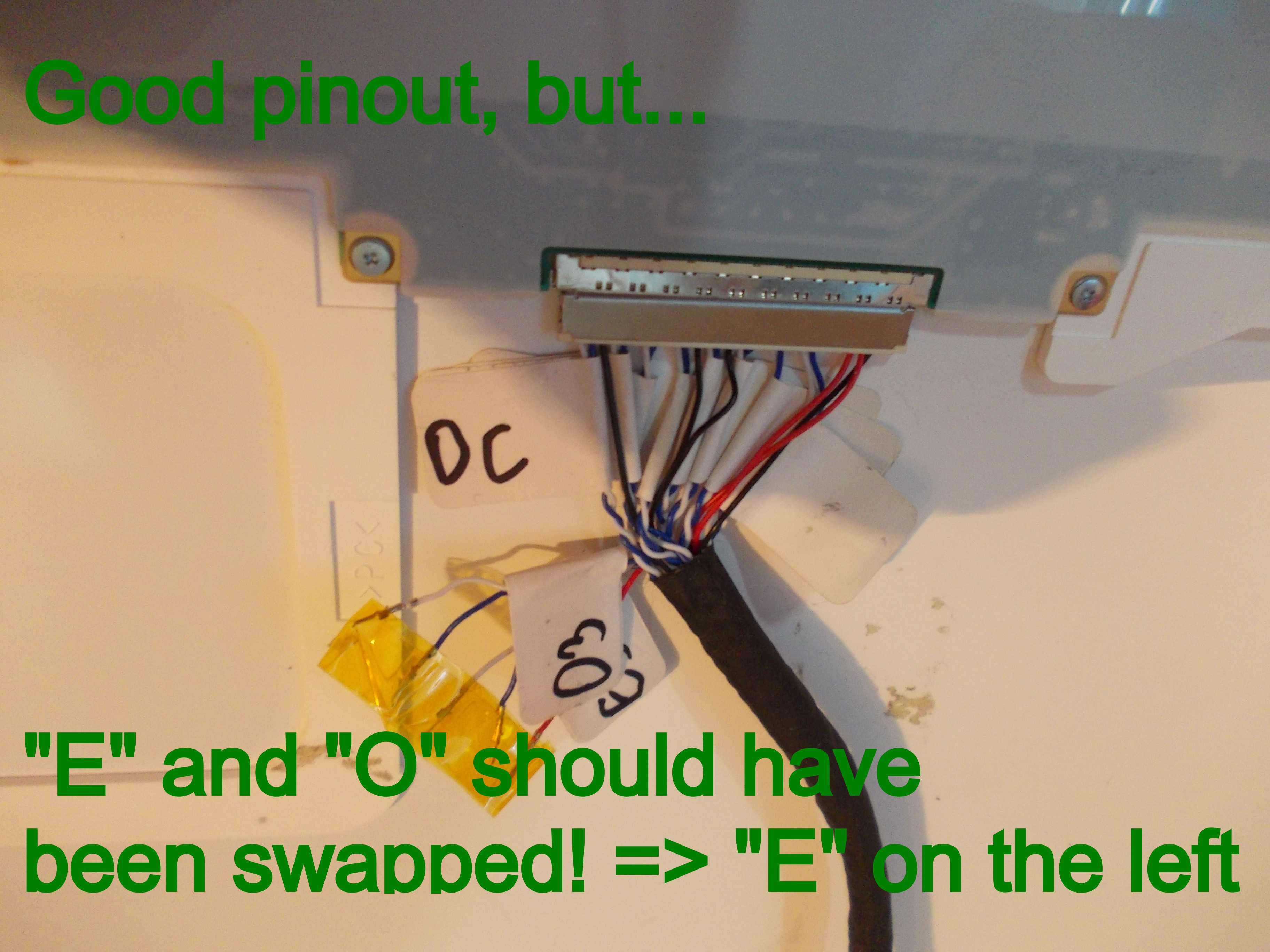
Here's *the* pinout that, chances are, you want:
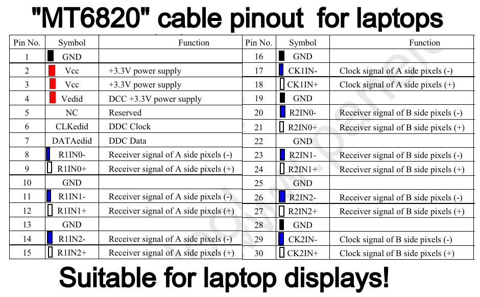
The above picture shows wire colors and exactly which pins I suggest you populate which way, as well as reminds you of the LVDS wire polarity colors. "R1*" wires should be "O" (LVDS Odd) and "R2" wires should be "E" (LVDS Even). Don't forget - white wires are + and blue wires are - !
"E3" and "O3" wires will be left hanging - that is perfectly fine. Wrap them in tape or heatshrink individually - don't let them short out among themselves or inside the case!
Not all the grounds are needed, but it is good practice to have at least one ground wire next to panel power (where pinout demands it), as well as to surround your LVDS clocks with ground wires so that they don't impact neighbouring signals - the default HX6810 cable has just enough ground wires to do that perfectly!
-There's three VCC (red) cables in the pinout but you only show two inserted on the picture! What do I do with the third one?
As the pinout diagram above suggests, put the third wire into 4th pin position - the one where the EDID VCC is. It won't help there, but it won't interfere there either, and it's one less wire hanging unconnected, which is good. My pictures were taken before I figured this out.
I started my first cable conversion for HX6810 by removing wires and marking them pair-by-pair:
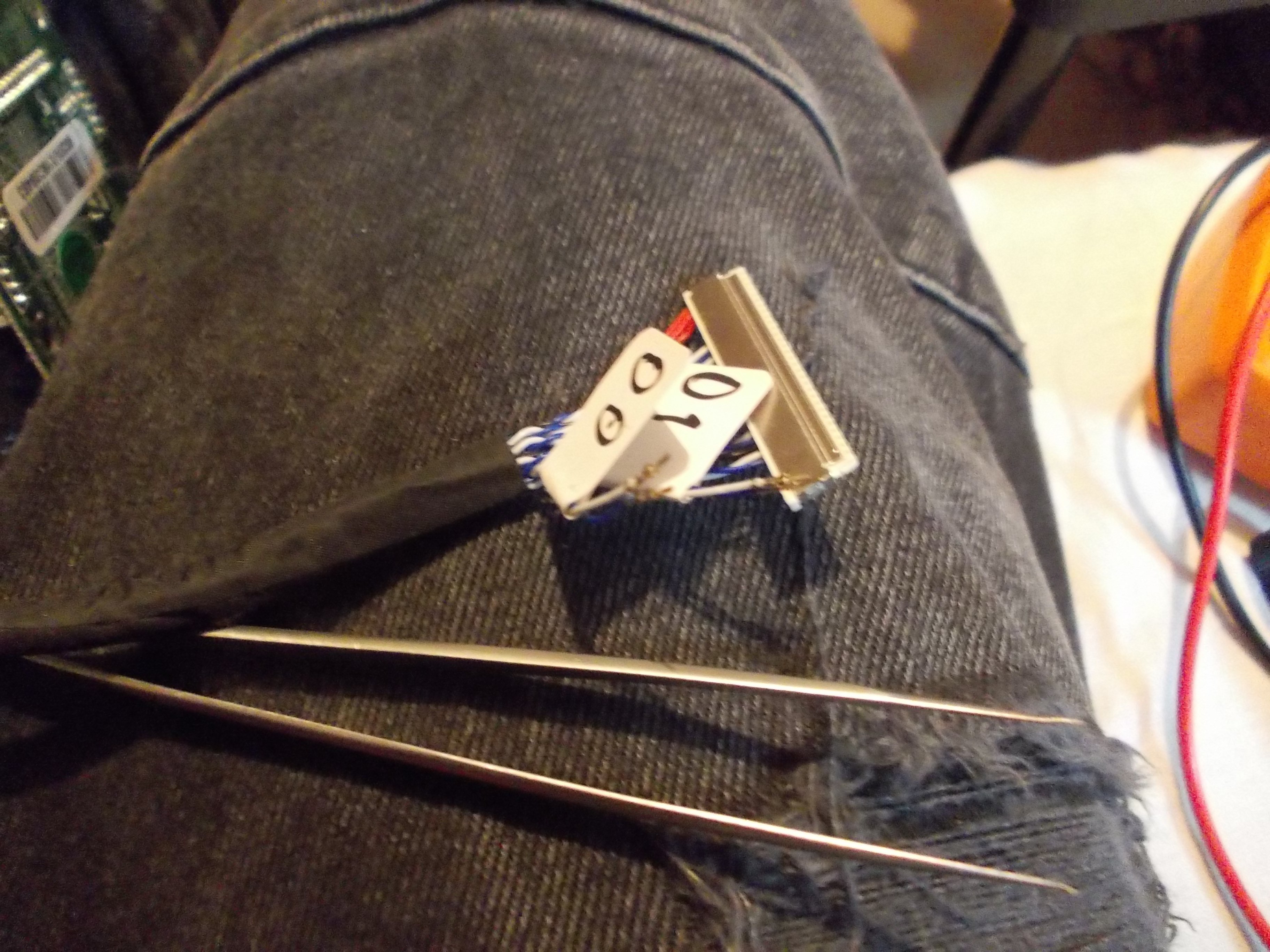
Not shown, but an xacto knife works best for gently bending the pin latches when removing the wires, tweezers, even sharp ones, don't work all that well.
I had some labels prepared, of course:
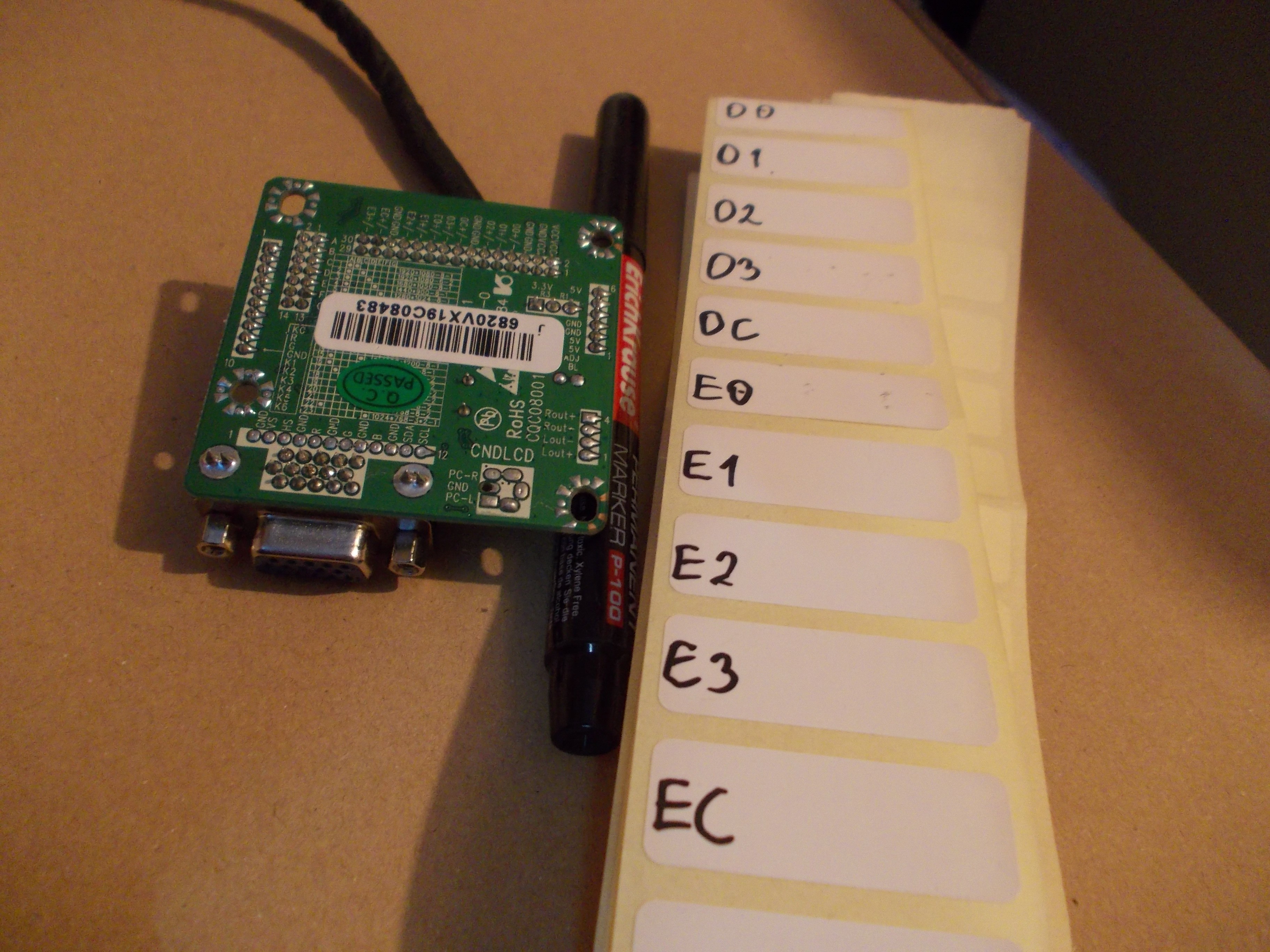
All removed and marked (except VCC and GND, these are obvious by their color)
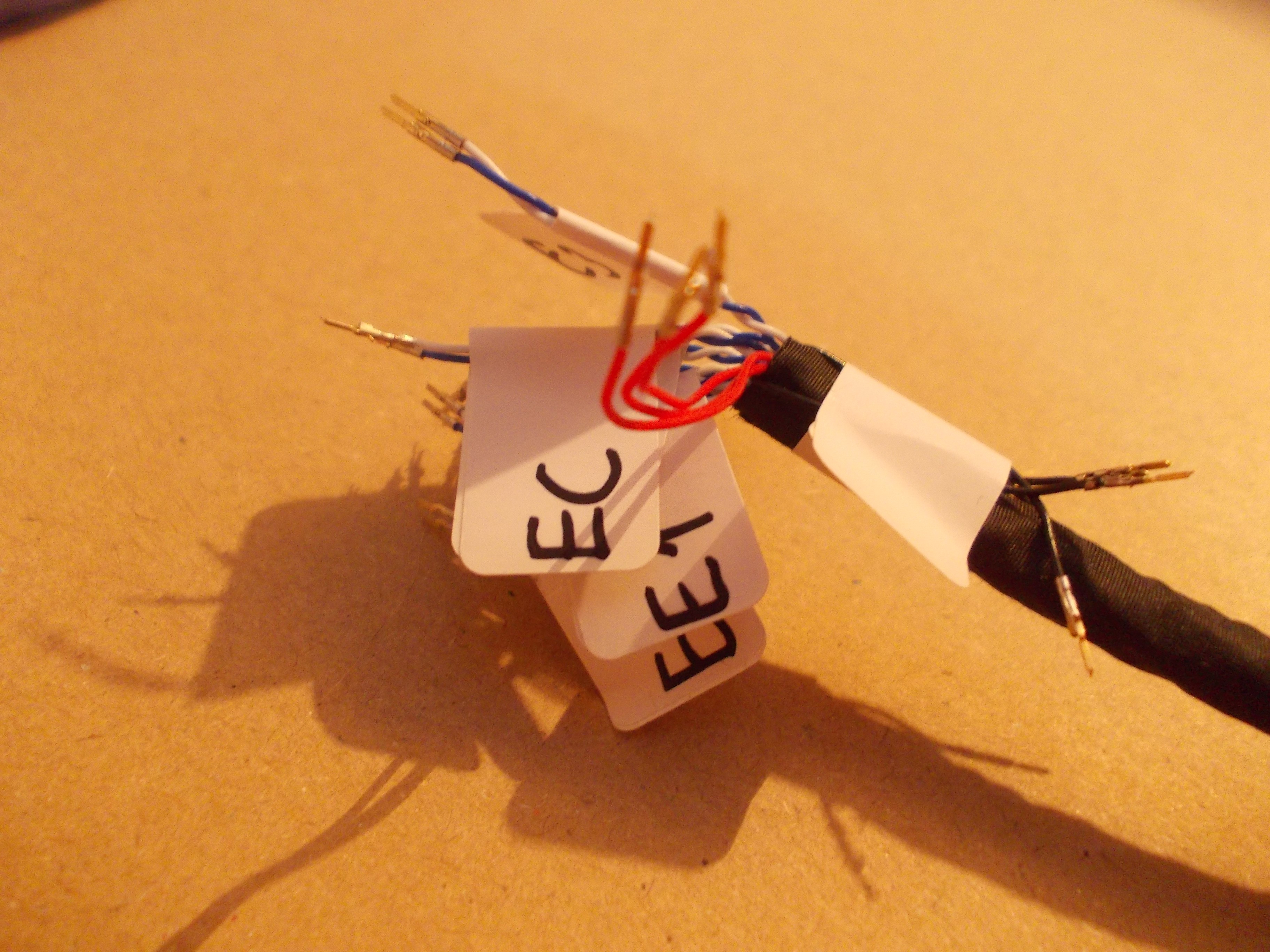
Then, I reinserted them into the shell following the proper pinout.
What does it look like with swapped wires?
After swapping E and O pairs, it started working great! I don't have a picture to show for it, just trust me ;-P
It was much easier to swap E and O pairs on the MT6820 board side. In fact, I've split the 2mm connector into 2x3, 2x6 and 2x6 portions just so I could do that easily! You can do that with some spare 2mm cable housings, filed down if needed - I will be selling small conversion kits for the experimenters among us, being able to swap&disconnect pairs actually does help sometimes!
I hear things about different panels treating "even" and "odd" differently, so what is marked as "odd" in the panel datasheet might very well be "even" when it comes to the MT6820 board output. In case that happens to you, be prepared to rewire your cable - sadly, AFAIK that's the only solution.
My next conversion, I did without marking anything - by having the LVDS cable inserted into the "MT6820" board and beeping the LVDS-side connector against the "MT6820" pinout markings on the PCB, using a multimeter. You can likely do it the same way, too - it's just a bit more daring =)
Discussions
Become a Hackaday.io Member
Create an account to leave a comment. Already have an account? Log In.