 Arya
Arya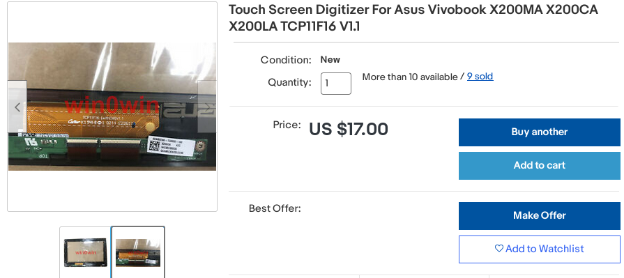
I bought two of these touchscreens on eBay, complete with controller boards and frames. I had one 11.6" display available to me already, and another one wouldn't be too hard to source in the future if I decided to. But first, gotta successfully reuse one of these to make sure my idea works.
[ TODO: pic ]
This one is certainly a USB device - most of modern laptop touchscreens are - so most of the laptop webcam reuse tips will apply. I need to find VCC, D+, D- and GND. There's 4 pins on the connector, so I don't have to worry about pins like EN and RST being present - they are on some touchscreens, but not this one.
The connector receptacle isn't something that I have a plug for when looking through my collection of random wire ends. This means I have to solder to the touchscreen board, sadly.
I'm using 4 individually insulated copper wires to solder to this board. To remove the insulation, I need to hold the wire end inside a blob of melted solder on the tip of my soldering iron so that the insulation burns away a bit, my soldering iron is set for 330C for that.
Some touchscreens actually want 5V VCC, others need 3.3V. How do I determine that? I usually just power them from 3.3V and then, if they fail to work, do research to see if perhaps they'd need 5V. This time, I had a connection problem and decided to double-check whether the touchscreen would work from 3.3V, so let's go through my process of researching whether a touchscreen is 3.3V or 5V.
Determining voltage
There's three ways to know a touchscreen's voltage with certainty:
- Markings on the touchscreen board itself (if the touchscreen PCB says "5V", it likely takes 5V)
- Measuring it on an assembled and connected laptop (not an option in this case)
- Schematics and boardviews
I didn't have 1 and 2, so I had to resort to 3. Asus X200CA doesn't have schematics available but there's boardview files. With OpenBoardView and the FZ key, I was able to open the boardview file and browse it. Now, where do I find the touchscreen connector?
Sometimes the touchscreen cable is a separate cable, and sometimes it's the same cable that also carries the display signals, and I need to know this to know which connector to look for touchscreen signals on. I looked up "x200ca cable" on eBay and found this:
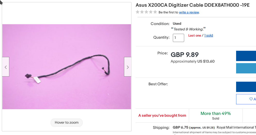
Looks like exactly the cable we need, one connector (right) is the kind of connector that plugs into our touchscreen controller board, and another one (left) is a Molex connector often used in laptops. So, the touchscreen has a separate connector. I could look up an "Asus X200CA teardown" video on YouTube and see exactly where that wire goes, but I saved a bit of time by googling "X200CA motherboard" and looking at images:
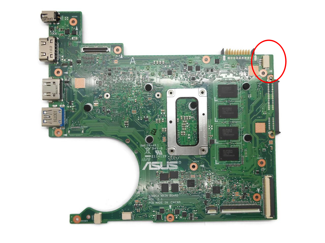
This connector instantly looked like the thing I needed. I located it on the boardview and, indeed, it has GND, USB signals and 3.3V:
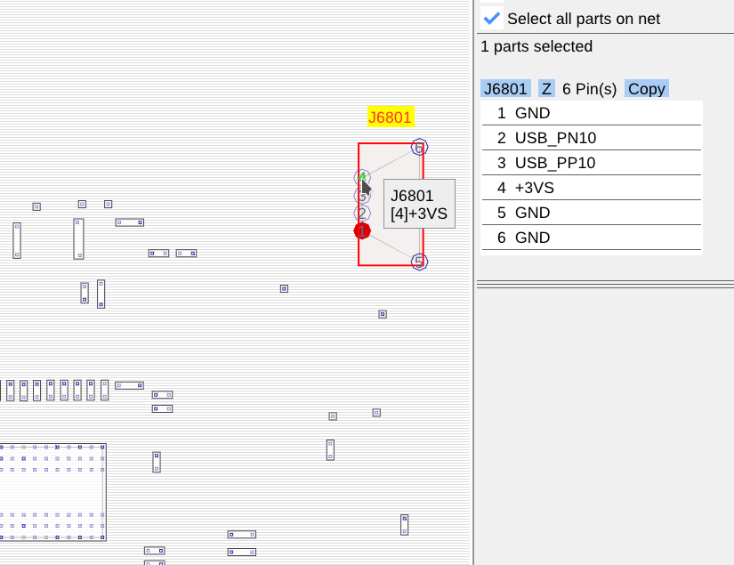
So, it's decided, the touchscreen wants 3.3V, and it's good to know that for sure - now I won't think "oh, maybe it needs 5V after all" and end up accidentally destroying it.
Determining pinout
The "determining voltage" part isn't necessary if you're not having doubts about the right voltage, that'd happen if the touchscreen fails to work at 3.3V, for instance. Otherwise, I'd say, you are pretty safe just powering it from 3.3V.
The pinout, however, has to be determined. I usually take a multimeter, find GND, then VCC, then USB D+ and D- - as the latter are hard to tell apart, I try them in one polarity and swap them if they don't work.
[ TODO: pic ]
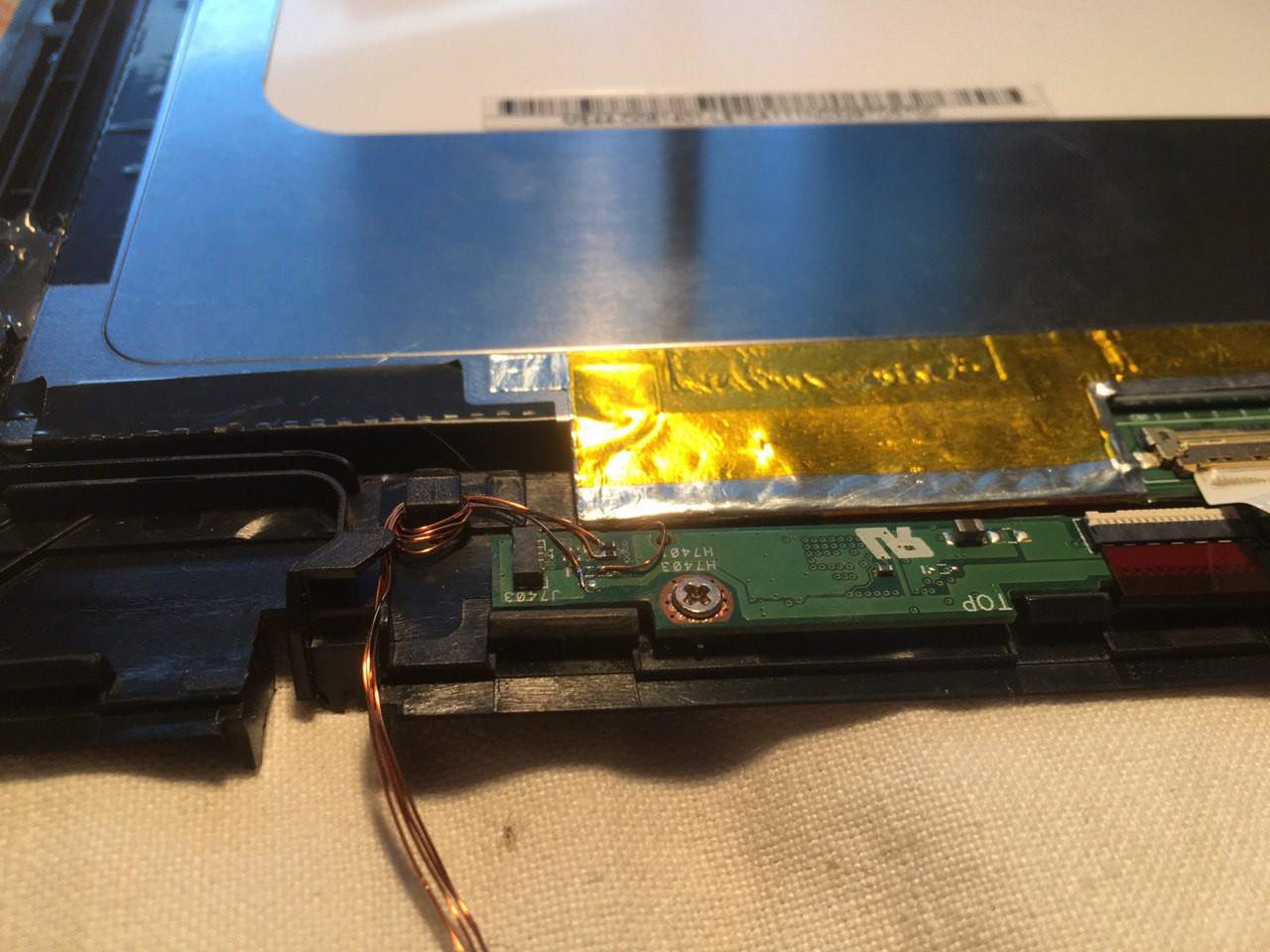
This controller board is already connected to the touchscreen glass and screwed to the touchscreen frame. I see no use in disconnecting and unscrewing it, there's more than enough exposed pins on the part of the board accessible to us.
[ TODO: pic ]
GND is likely to be at the screw hole - checking with a multimeter, there's indeed connectivity between one of the pins on the 4-pin connector and the metal around the screw hole. It also is connected to all of the capacitors on the board, so that cements it, we found GND. I won't solder a wire to the screw hole itself, but instead to one of the other GND points on the board.
[ TODO: pic ]
These two traces going to two resistors are an obvious differential pair, so there's our USB. That leaves the one remaining pin as VCC.
[ TODO: pic ]
VCC is very prominent on this board, it's a thick trace going somewhere to the right from the connector. Even the connector's mechanical pins are connected to VCC and not to GND, as usual - not that it matters this time.
Now, I just connect wires from my small microUSB+3.3V breakout board to the touchscreen, and, after swapping D+ and D- wires once (at the breakout, not at the connector), it works:
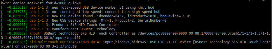
Of course, it's out-of-the-box on Linux, with Windows, your mileage may vary. Sometimes Windows wants drivers, even if it's a popular touchscreen - usually isn't needed with Linux, thanks to all of the in-kernel drivers.
I touch the touchscreen (from its front size) and the mouse pointer of my laptop moves! Ain't that nice. After fastening the wires a bit, I decide that I've successfully reused this touchscreen. Now it just needs a display fitted to it:
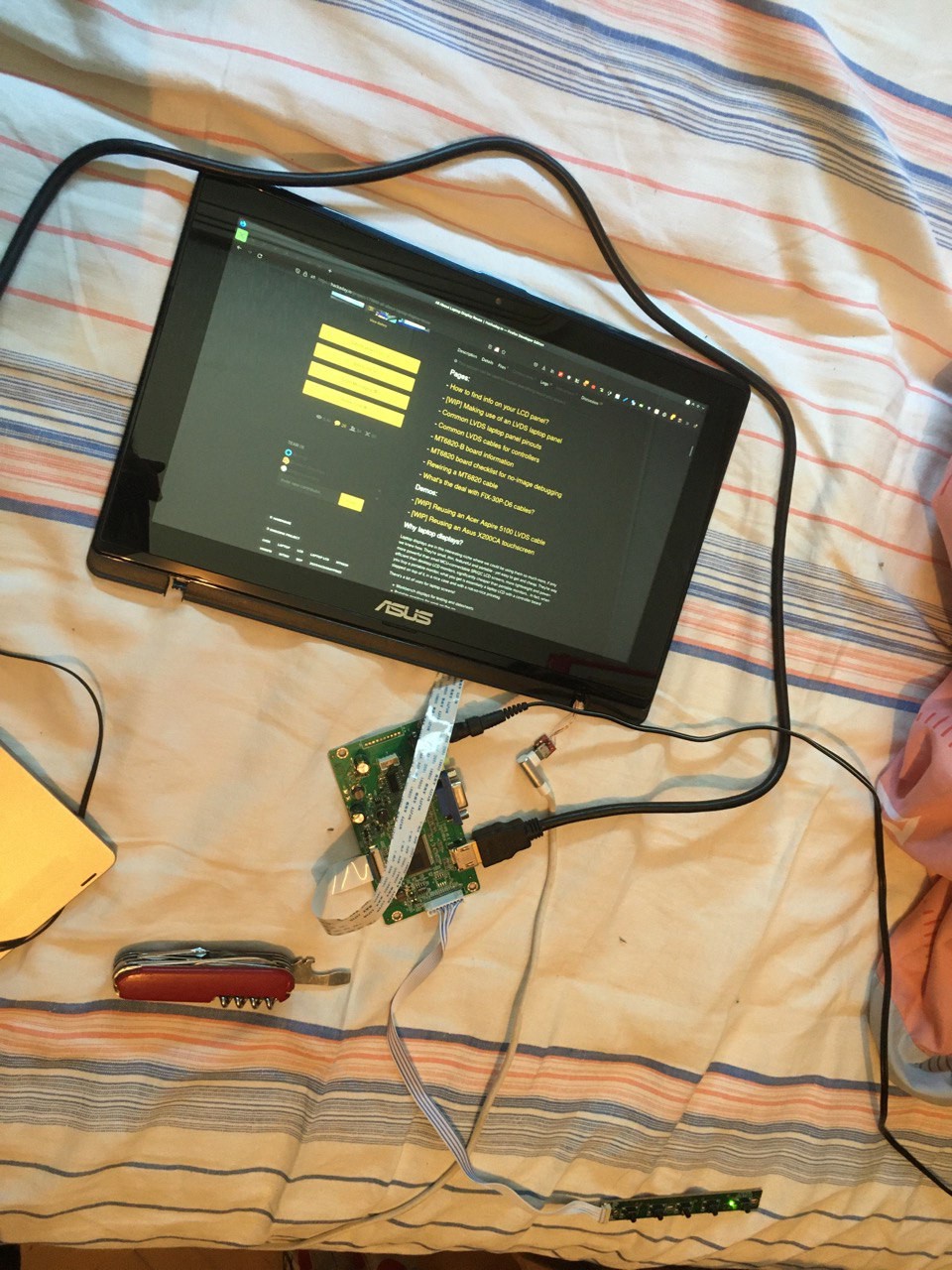
Perfect.
Discussions
Become a Hackaday.io Member
Create an account to leave a comment. Already have an account? Log In.