 Nuri Erginer
Project Log Direct Links:
- Functional Block Diagram
- PnPAssist V2 Source Files
- PnPAssist V2 Components List
- Controller Board Schematics
- PnPAssist V2 design decisions
Why I build this?
I often find myself assembling PCB boards that I designed for my own R&D activities or for a small number of boards I prepared for sale on Tindie. This process is a little bit painful. First I find the location and value of the component from the CAD software. Then I find the right value/package component from my boxes among dozens of components and locate that component by determining its place on the blank PCB. This process continues repeatedly for each component. I designed a tool for myself to improve this time-consuming and error-prone process.
I take a look at the PnP machines for a long time and made researches to make or buy one for myself. But every time I gave up. It frightened me whether it would be accurate enough and the time consuming preparation phase for each new type of board. After all, I was making dozens from one type of board, not hundreds of the same board. There was no enough place in my room for such a large machine. That's why I decided to design a simpler and easier device.
How to Use It?
This machine works with a PnP mount file. Most of the CAD software (may be all of them) for PCB design has option to export this file. For Autodesk Eagle you can export from File > Export > Mount SMD menu
This text file contains the name, X coordinate, Y coordinate, angle, value and the package of the components on the PCB.
Example Format:
R5 14.31 6.59 90 470ohm M0805
R6 16.41 10.04 180 470ohm M0805
Save this mount file to an SD card and put it on the PnPAssist SD card reader. The machine will home itself on power up.
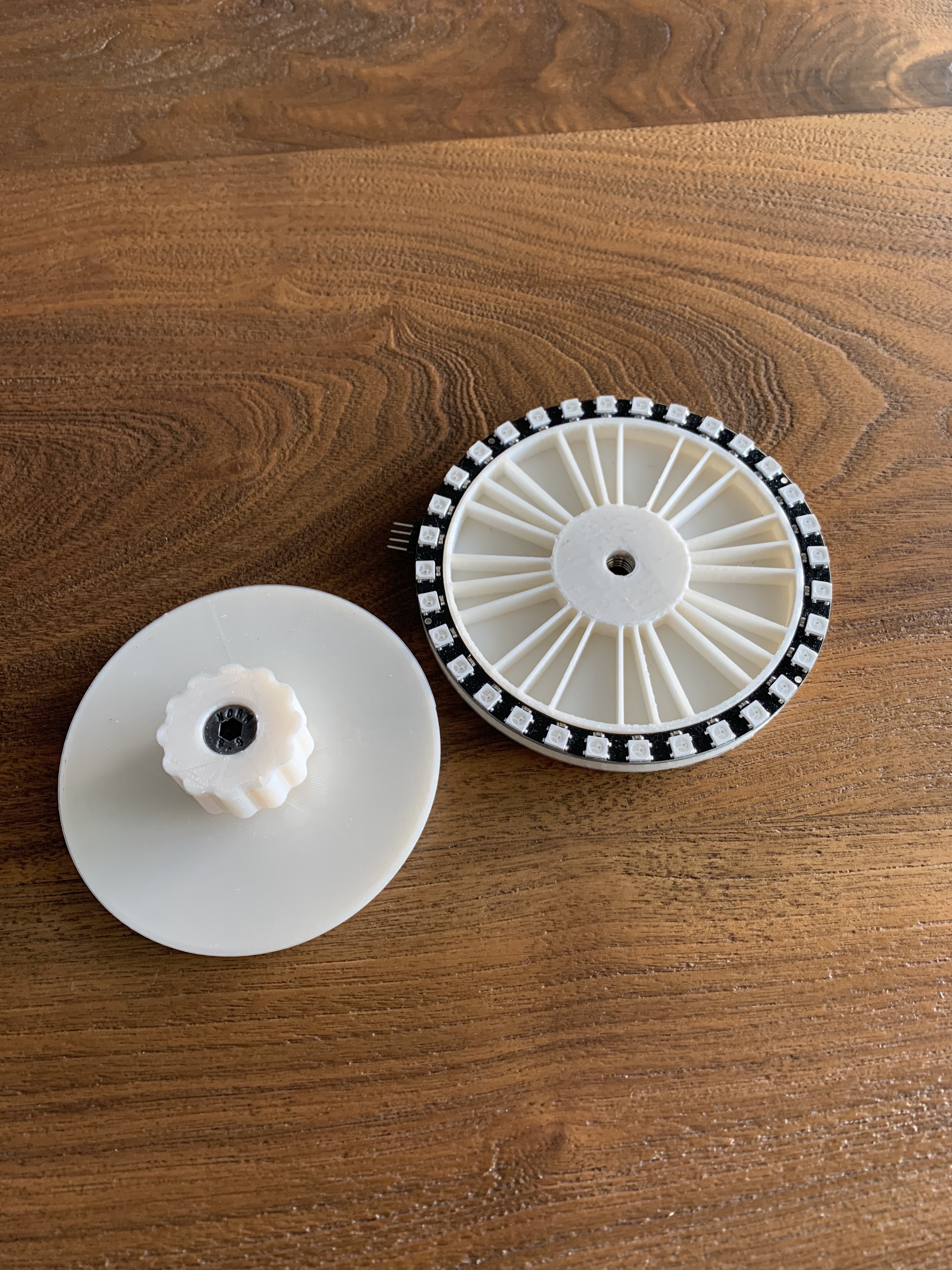
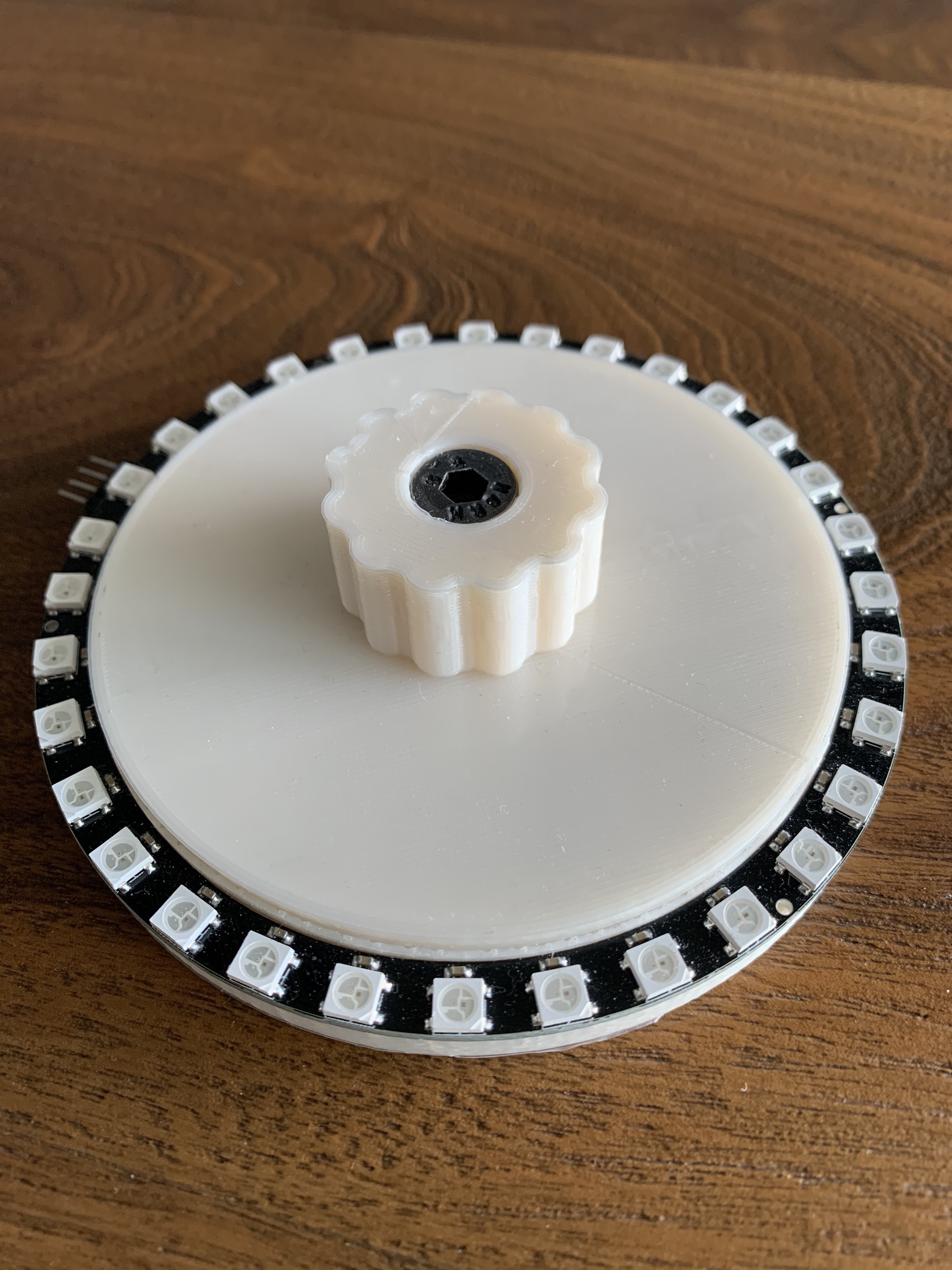
Place the empty board on the rotary disk. Now you are ready to PnP. For the fist component you need to adjust the machine position under the laser cross. Every time you click the on board switch the machine moves in order to center the next component under the laser cross and the microscope. If you do not have a microscope You can only use the laser cross indicator. When the next component is at the center of the main rotary axis you can rotate the machine to feel your self comfortable to put the component on its place. The machine will show you the name value and the package of the component that you will use on it's oled screen.
Kinematics
This machine has one linear and one rotary axis. The two lead screws move one center gear. This design have many advantages and simplifies the hardware design. The lead screws with center gear design locks the axis from moving and rotating freely and provide great precision. If you move only one of the motor the table moves and rotates at the same time. In this aspect there is a similarity with the CoreXY platforms. If you move the motors same amount at the opposite directions only the rotary axis moves. If you move the motors same amount at the same direction only Y axis moves. For this reason I decided to use only one step pulse signal from the micro controller to the motor drivers. This ensures that both motors rotate the same amount.
I use atan2 function to convert the Cartesian coordinates to Polar coordinates for the rotary axis. A polar coordinate system uses an angle and a distance from a center point to define a point in 2D space.
For the given x,y coordinate of a component (we read mount file line by line from SD card and parse the x,y coordinates) we calculate the angle and the radius (distance to the origin) of that point. You can see the calculations in CalcAngleRadius function in the firmware. After this calculations we need to rotate to the angle and move as much as the radius.
Accessories
I design an 3D model component box with led indicators. The main board will drive the LEDs in order to indicate the component you need to take from the component box.
Future Improvements
I listed below some improvements that I have planned to realize for the next version. Please feel free to write me your ideas and I will be more than happy to talk about them and add it to the road map.
PCB design for the machine.Done Find the files in the Github Repo- Search for smaller stepper motors (Nema 11) with lead screw. (https://www.aliexpress.com/item/4001142065584.html?spm=a2g0o.productlist.0.0.48376f1cL2pVYI&algo_pvid=51625f68-3d41-4e58-a6e6-4123678a3538&algo_exp_id=51625f68-3d41-4e58-a6e6-4123678a3538-0)
- Change the pitch of the lead screw for better 3D printable center gear.
- Change the center of the machine for a better balance.
- Menu system with rotary encoder for better UI.
Choose a big ordinary bearing for the machine center rotary axis.Files updated accordinglySpring Compression Contact for powering the machine. This will move the power cable from the top side to bottom side and It will be easier to rotate the machine by hand.I choose to use a slip ring It is in the BOM- This version of the firmware first rotate one axis and after completion of the rotary movement it moves along with the y axis. In future versions the system can move in both axis at the same time. This brings software complexity so I did not implement it for this version.
- I will use trinamic stepper drivers for the next version.