Jithin Sanal
Remote Controlled Tank
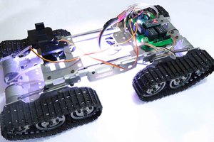
This time I have a rough Terrain Robot with 4 Wheel Drive and dedicated suspension for it to travel over rough terrain. Check it out.
Why not build one for yourself? Here we will learn how to build an Off-Road Wireless Multipurpose 4 Wheel Drive Arduino Tracked Robot for a smooth ride over rough terrain – A DIY Rough Terrain Wireless Crawler with Suspension.
We will provide you with the design, code, circuit diagrams, and links to buy your own robot kit, chassis, and sensor modules used in this project.
HC12
HC 12 is a really cheap long-range wireless module that can be used for wireless serial communication over a long distance of up to 1.7 KM. The module is really compact lightweight and breadboard-friendly which makes this the best wireless controller for our project.
Joystick
This is the most widely used robotic controller which comes with a various robot DIY kit that is built to work with arduino. The design is quite simple and is very easy to use. It uses two potentiometers to calculate the motion in the x-axis and y-axis and a switch to sense the button press.
This can be easily connected to the arduino’s analog pins and read analog values directly.
Code for testing the joystick is available down below. Feel free to download/edit it as per your need.
Before uploading the main code, make sure your joystick works by using this code. Download the code from the above link. In this example, what we are doing is simply collecting the data analog outputs from the Joystick using the analog pins (A0, A1, A2) of Arduino. These values are stored in the variables and are later printed on the serial monitor
We will divide this tutorial into 2 Parts – The Remote Controller and The Robot
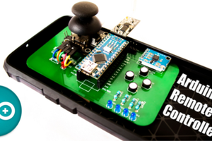
1- The Remote Controller
The Transmitter consists of a breadboard in which we mount all the sensors and components to get the data that is used to drive the Off-Road Wireless Surveillance 6 Wheel Drive Robot. This includes an accelerometer, a joystick, and an HC12 module.
We will use the accelerometer as well as the joystick to control the off-road robot. For now, we will use the joystick button to close the robotic hand. The data from these sensors are transmitted wirelessly to the DIY robot using an HC12 module.
In the previous post, I showed you how you can make a remote controller using HC12 Wireless Module, Joystick, and Accelerometer. We can use the same remote for this project also. Click here to know more about the HC12 Remote Controller.
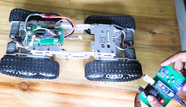
The Circuit Explained
Now let us take a look at the circuit of our motor driver board. Looks a bit messy? Don’t worry, I will explain it to you.
The Schematics
So I used Altium Designer to draw the circuit and design the PCB. It is a powerful tool that can be used to design and create your own PCBs for your project as well as complex and multiplayer PCBs for industrial use. Here is the link to the Altium trial version.
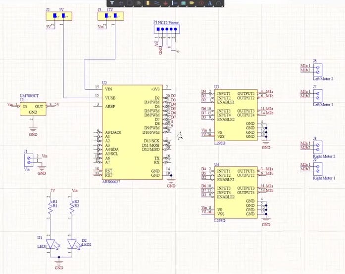
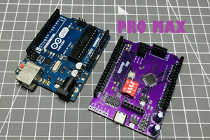
Here, I have designed a PCB layout where you can easily mount your Arduino Nano 33 IOT, L293D ICs, and the supporting components and set this up without using messy wires and cables hanging around. The board is lightweight and can be powered using a 9V battery or a 9-12 V power adapter.
We need to power up the whole circuit and drive all 4 motors using L293D/L298N motor driver and our Arduino board. We need a power source that can provide enough current. So, I decided to go with a 12V LiPo battery.
The input power is connected to a 7805 regulator. 7805 is a 5V regulator that will convert an input voltage of 7- 32V to a steady 5V DC supply. There are indicator LEDs across various points for easy troubleshooting. You can either power your Arduino using 12V or regulated 5V output from the 7805 regulators. You can select that using a jumper.
Powering Arduino depends upon the type of board you are using. Here I am using...
Read more »
 Lithium ION