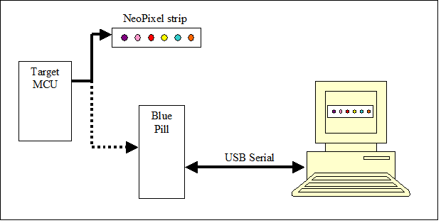
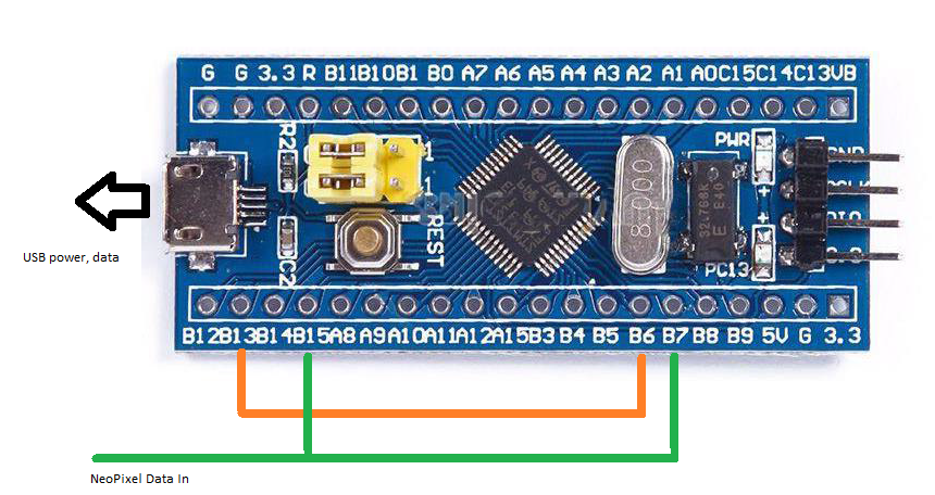
Close
0%
0%

NeoPill

A STM32 Blue Pill-based NeoPixel emulator

Similar projects worth following
Ever need to blink your NeoPixels but you either didn’t have enough or they’re already installed in a project you don’t have within easy reach?

Enter the NeoPill, an easy to make NeoPixel emulator that taps off of your target microcontroller to graphically emulate NeoPixels on your PC. Consider it a NeoPixel to USB bridge.

This project started as an investigation into STM CubeMX operation – I’d be lying if I said configuring the powerful STM32 timers were easy – and after looking at examples online, reading (and re-reading) manuals, and spending time with the debugger I got something working ok.

All you need is:
- A STM32 Blue Pill.
- A few jumpers.
- USB cable.
- A PC running some python code.

NeoPixel timing

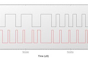
NeoPixels use a self-clocking signal along a single wire to serially send “1” and “0” bits, in the timing format below (from the Adafruit website.)

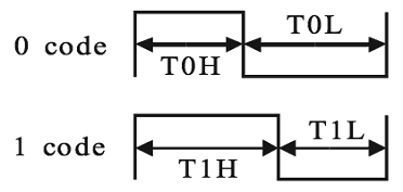
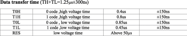
The RES signal is also known as Data Latch.

NeoPill function

NeoPill converts the NeoPixel serial data into bytes and sends those bytes to a PC over USB. However, NeoPixel data is always written as a frame, where all the LEDs in a string are written, followed by a short pause called Data Latch. When the code running on the PC is ready for pixel data it expects to be synced with a frame. Once synced, the pixel data streams out and there is no other syncing involved.

If the target sends a partial frame then the NeoPill will definitely lose sync. This may occur during a code update or reset of the target. See the “python code” section on sync recovery.

 The PC can send a few simple text messages to NeoPill to cause a resync, and one message to alter the Neopixel serial timing if required to support other addressable LEDs.

NeoPill Block Diagram

NeoPill Uses the following STM32 components:

  • timers TIM2,3,4,
  • serial peripheral interface SPI2,
  • direct memory access DMA,
  • USB interface, 72MHz system clock configuration with 48MHz USB clocking (not shown.)

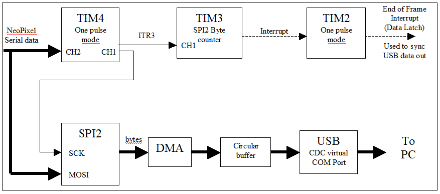
TIM4 derives the SPI2 clock (SCK) by generating a delayed pulse of 550ns after the start of either T0H or T1H, thus clocking in either a 0 or 1 bit into SPI2. SPI2 converts the NeoPixel serial data into bytes, storing them via DMA into a circular buffer. The main loop sends these bytes out the USB port to the PC. The USB interface is provided by CubeMX middleware.

An easy way to detect the Data Latch signal is to use the incoming serial data to retrigger a One Pulse Mode timer, which unfortunately is not available in the STM32F103 series. Or use a 555 timer chip. :)

A solution to detect Data Latch uses TIM3 to count NeoPixel serial data pulses and every 8 counts (or every byte received) generate a software interrupt to restart TIM2 One Pulse Mode timer (with delay). When a frame of pixel data is complete there is a pause for Data Latch. This pause is typically greater than 50us. TIM2 generates an interrupt after this 50us delay. This TIM2 End of Frame signal syncs the pixel data when the python code requests.

bluepill_neoemu_clk.hex

NeoPill STM32 Blue Pill Hex file.

hex - 58.00 kB - 05/22/2021 at 02:37

Download

ledmatrix.yaml

NeoPixel matrix configuration.

yaml - 920.00 bytes - 05/22/2021 at 02:35

Download

ledstrip.yaml

Single NeoPixel strip configuration.

yaml - 646.00 bytes - 05/22/2021 at 02:35

Download

stripsim.py

Python code for NeoPill. For python 3.8.1.

plain - 16.78 kB - 05/22/2021 at 02:32

Download

  • 1 × STM32F103C8T6 Blue Pill dev board Discrete Semiconductors / Power Transistors and MOSFETs
  • 3 × Jumper wires
  • 1 × Jumper/clip to target board
  • 1 × USB cable Electronic Components / Misc. Electronic Components
  • 1 × PC running python

  • 1
    NeoPill Firmware and Operation

    NeoPill Firmware

    STM32 Blue Pill Development Environment Used

    • STM CubeMX 6.1.1
    • Keil uVision 5.26 (Lite version)
    • STM32CubeProgrammer  v 2.6.0

    NeoPill Operation

    1. With USB cable plugged into the Blue Pill verify no ground loop to target board.
    2. Both target and Blue Pill powered off (unplug USB.)
    3. Jumper NeoPixel serial data to PB7 and PB15. These are 5V tolerant inputs.
    4. Jumper PB6 to PB13.
    5. Verify common grounds with target, or jumper target GND with Blue Pill G.
    6. Plug USB cable into PC, powering Blue Pill. Note LED PC13 flashing at 10Hz.
    7. Power on target. It’s ok if its NeoPixels are operating.
    8. Start PC python code. LED PC13 flashes at 5Hz if no NeoPixel data present. Once python code syncs LED PC13 flashes at 1Hz. 
    9. Observe graphics display.

    Blue Pill Pin

    In/Out

    Function

    Desc

    PB7

    In

    TIM4 CH2

    Neopixel serial data

    PB6

    Out

    TIM4 CH1

    Clock for SPI2 -> PB13

    PB13

    In

    SPI2 SCK

    SPI2 clock input <-PB6

    PB15

    In

    MOSI

    Neopixel serial data

    G


    Neopixel serial data GND

  • 2
    Python Code, Stripsym.py

    Stripsym.py

    On the PC side a small lump of python code, Stripsym.py, reads a YAML file to configure

    • the pygame graphics window,
    • number of LEDs,
    • and LED format.

    The number of LEDs and format must match the target. A strip or matrix configuration is also supported. For a matrix only the progressive scan is supported, or for Adafruit’s NeoMatrix the settings: NEO_MATRIX_TOP+NEO_MATRIX_LEFT+NEO_MATRIX_ROWS+NEO_MATRIX_PROGRESSIVE

    Once configured,

    • the desired serial port (COM port) is opened,
    • a sync command is sent to NeoPill,
    • and serial data is read and queued.

    Upon receiving a frame of pixel data (number of LEDs * 3 or 4 bytes) the appropriate format is applied, gamma corrected, and displayed in the graphics window.

    Python environment:

    • python 3.8.1
    • pygame 2.0.0
    • pyserial 3.5
    • pyYAML 5.4.1

    YAML file configuration options:

    • Strip or matrix configuration
    • LED formats:  GRB, GRBW
    • Number of LEDs:  1..N, where N may be large if your PC is capable.
    • Or matrix size, n by m.
    • LED display shape:  Circle, rectangular
    • Intergap size: 1..n
    • Graphics window size
    • Optional timing adjustment
    • Serial port (Windows COM port)
    • fps_limit
  • 3
    Runtime controls

    command line:

    python stripsim.py ledstrip.yaml

    or

    python stripsim.py ledmatrix.yaml

    Once running,

    • Click the mouse on the display to show data queue stats, FPS, input data rate.
    • Up/Dn arrows adjust gamma.
    • ‘s’ performs a sync operation with NeoPill, usually needed after the target is restarted.

View all 4 instructions

Enjoy this project?

Share

Discussions

AgentPothead wrote 06/20/2021 at 02:09 point

The hardest part of all this was just figuring out how to interface the STM32F103C8T6 with the computer.

  Are you sure? yes | no

Randy Elwin wrote 06/20/2021 at 06:24 point

From scratch you'll have to download about 300 Mbytes of dev code to flash a 25Kbyte file into the Blue Pill...

  Are you sure? yes | no

AgentPothead wrote 06/20/2021 at 14:42 point

Hahaha yeah, that sounds about right! It wasn't really that bad once I realized I could use UART and didn't "need" an stlink.

  Are you sure? yes | no

marble wrote 05/26/2021 at 19:40 point

I just cloned the repo and generated code for a Makefile project, copied over the three files and it compiled without a warning. +1

  Are you sure? yes | no

Randy Elwin wrote 05/27/2021 at 03:10 point

Great! STM CubeMX does a good job getting the environment set up.

  Are you sure? yes | no

Similar Projects

Does this project spark your interest?

Become a member to follow this project and never miss any updates