Subhajit
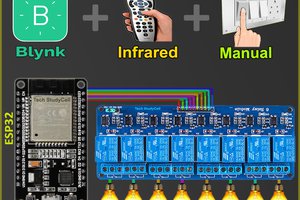
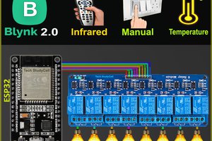
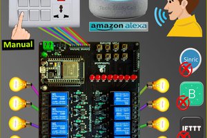
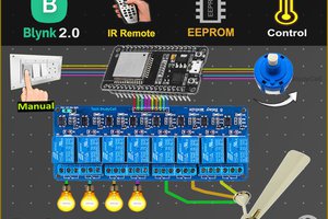
In this IoT project, I have shown how to make IoT-based ESP32 Home Automation using Alexa, IR remote, and switches to control an 8-channel relay module with and without internet. If the internet is not available, then you can control the home appliances from IR remote & manual switches.

During the article, I have shown all the steps to make this home automation system.
Tutorial Video on Blynk ESP32 Smart Home System:
This ESP32 control relay module has the following features:
- Control home appliances with Alexa (voice control).
- Control home appliances with IR Remote.
- Control home appliances with manual switches.
- Monitor real-time feedback in the Blynk App.
- Control home appliances manually without internet from IR remote and switches.
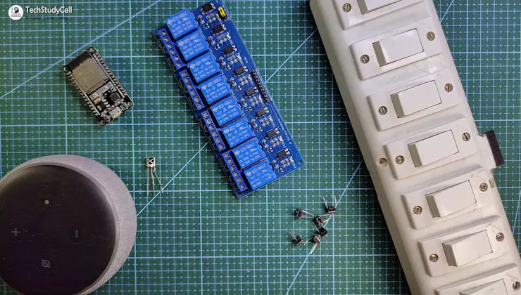
If you don't want to use PCB, you can also make this IoT project using an 8-channel relay module, ESP32, and IR receiver sensor.
Circuit Diagram of the ESP32 Projects:
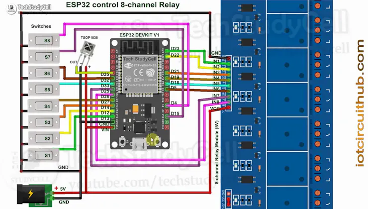
This is the complete circuit diagram for this home automation project. I have explained the circuit in the tutorial video.
The circuit is very simple, I have used the GPIO pins D23, D22, D21, D19, D18, D5, D25 & D26 to control the 8 relays.
And the GPIO pins D13, D12, D14, D27, D33, D32, D15 & D4 are connected with Switches to control the 8 relays manually.
And the output pin of the IR Receiver is connected with GPIO D35.
I have used the INPUT_PULLUP function in Arduino IDE instead of using the pull-up resistors.
I have used a 5V 5A DC power supply.
Required Components:
- ESP32 DEVKIT V1 board
- 8-channel SPDT 5V Relay Module
- TSOP1838 IR receiver
- Manual Switches or Pushbuttons
Required Components for the PCB:
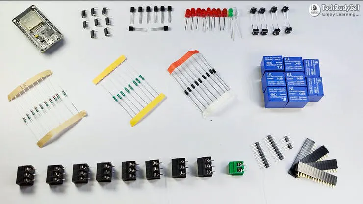
- 1. Relays 5v (SPDT) (8 no)
- 2. BC547 Transistors (8 no)
- 3. PC817 Optocuplors (8 no)
- 4. 510-ohm 0.25-watt Resistor (8 no) (R1 - R8)
- 5. 1k 0.25-watt Resistors (10 no) (R9 - R18)
- 6. LED 5-mm (10 no)
- 7. 1N4007 Diodes (8 no) (D1 - D8)
- 8. Push Buttons (8 no)
- 9. Terminal Connectors
- 10. 5V DC supply
Required Software:
- Arduino IDE
- Amazon Alexa App
Testing the Circuit Before Designing the PCB:
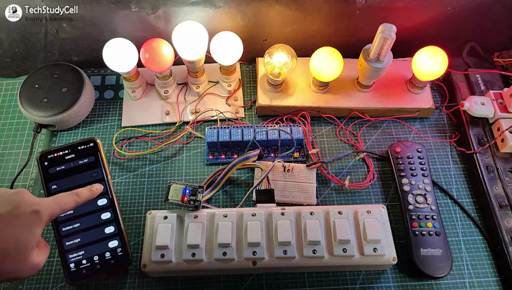
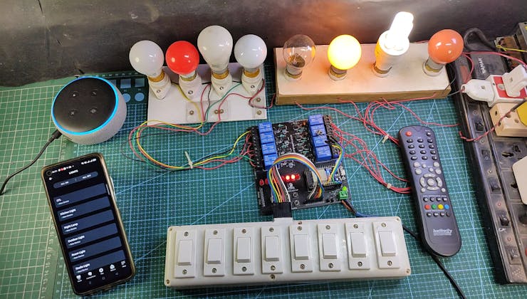
Before designing the PCB, I have made the complete circuit using ESP32, an 8-channel relay module, IR receiver, and manual switches.
As you can see, the relay can be controlled from the IR Remote, manual switches, and Amazon Alexa App. In the following steps, I have explained the complete projects in detail, also shared the code and PCB Garber file.
First, let's discussed all the features of this Alexa Home Automation system in detail.
Control Relays With Voice Commands Using Alexa:
If the ESP32 module is connected with the WiFi, you can control the home appliances from Amazon Alexa App, IR Remote, and manual switches.
You can control, monitor the real-time status of the relays in the Alexa App. The ESP32, Amazon Echo Dot should be connected to the same WiFi network.
ESP32 Control Relay With IR Remote:
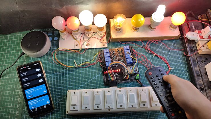
You can always control the relays from the IR remote. For this project, you can use any IR remote.
I will explain how to get the IR codes (HEX codes) from any remote in the following steps.
And if the ESP32 connected with Wi-Fi, then you can also monitor the real-time feedback in the Amazon Alexa App.
Control Relays Manually With Switches:
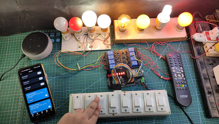
If the WiFi is not available, you can also control the relays from the manual switches.
The ESP32 will check for the WiFi after every 3 seconds. When the WiFi is available, the ESP32 will automatically connect with the WiFi.
Please refer to the circuit diagram to connect the manual switches.
Designing the PCB for ESP32 Projects:
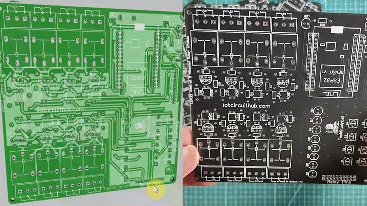
To make the circuit compact and give a professional look, I have designed the PCB after testing all the features of the smart relay module on the breadboard.
You can download the PCB Gerber file of this home automation project from the following link:
https://drive.google.com/uc?export=download&id=1Y8rXnczq6baxAKOrBEE8aro-uqcK0J93...
Read more »