 Subhajit
In this IoT project, I have shown how to make IoT-based ESP32 Home Automation using Alexa, IR remote, and switches to control an 8-channel relay module with and without internet. If the internet is not available, then you can control the home appliances from IR remote & manual switches.

During the article, I have shown all the steps to make this home automation system.
Tutorial Video on Blynk ESP32 Smart Home System:
This ESP32 control relay module has the following features:
- Control home appliances with Alexa (voice control).
- Control home appliances with IR Remote.
- Control home appliances with manual switches.
- Monitor real-time feedback in the Blynk App.
- Control home appliances manually without internet from IR remote and switches.
If you don't want to use PCB, you can also make this IoT project using an 8-channel relay module, ESP32, and IR receiver sensor.
Circuit Diagram of the ESP32 Projects:
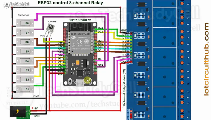
This is the complete circuit diagram for this home automation project. I have explained the circuit in the tutorial video.
The circuit is very simple, I have used the GPIO pins D23, D22, D21, D19, D18, D5, D25 & D26 to control the 8 relays.
And the GPIO pins D13, D12, D14, D27, D33, D32, D15 & D4 are connected with Switches to control the 8 relays manually.
And the output pin of the IR Receiver is connected with GPIO D35.
I have used the INPUT_PULLUP function in Arduino IDE instead of using the pull-up resistors.
I have used a 5V 5A DC power supply.
Required Components:
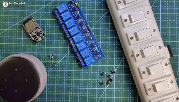
- ESP32 DEVKIT V1 board
- 8-channel SPDT 5V Relay Module
- TSOP1838 IR receiver
- Manual Switches or Pushbuttons
Required Components for the PCB:
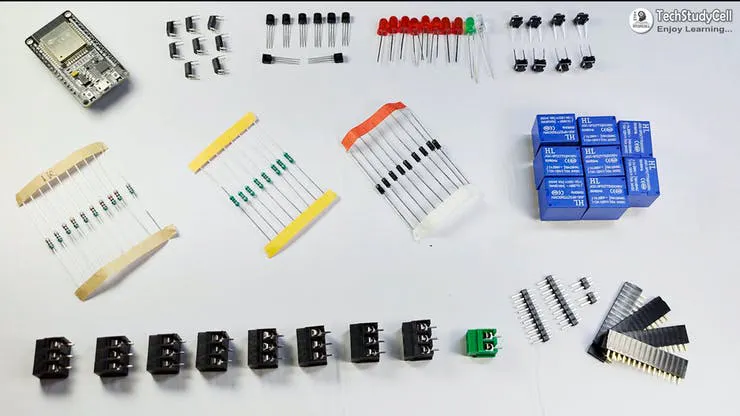
- 1. Relays 5v (SPDT) (8 no)
- 2. BC547 Transistors (8 no)
- 3. PC817 Optocuplors (8 no)
- 4. 510-ohm 0.25-watt Resistor (8 no) (R1 - R8)
- 5. 1k 0.25-watt Resistors (10 no) (R9 - R18)
- 6. LED 5-mm (10 no)
- 7. 1N4007 Diodes (8 no) (D1 - D8)
- 8. Push Buttons (8 no)
- 9. Terminal Connectors
- 10. 5V DC supply
Required Software:
- Arduino IDE
- Amazon Alexa App
Testing the Circuit Before Designing the PCB:
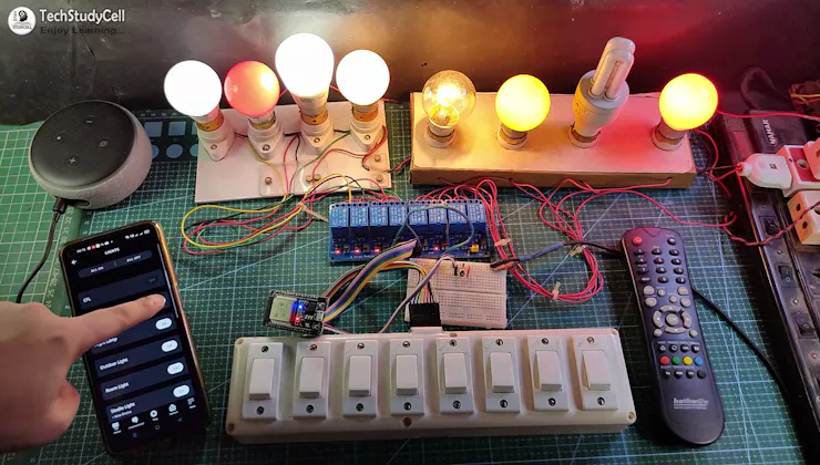
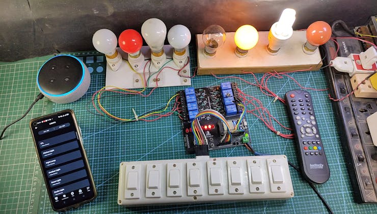
Before designing the PCB, I have made the complete circuit using ESP32, an 8-channel relay module, IR receiver, and manual switches.
As you can see, the relay can be controlled from the IR Remote, manual switches, and Amazon Alexa App. In the following steps, I have explained the complete projects in detail, also shared the code and PCB Garber file.
First, let's discussed all the features of this Alexa Home Automation system in detail.
Control Relays With Voice Commands Using Alexa:
If the ESP32 module is connected with the WiFi, you can control the home appliances from Amazon Alexa App, IR Remote, and manual switches.
You can control, monitor the real-time status of the relays in the Alexa App. The ESP32, Amazon Echo Dot should be connected to the same WiFi network.
ESP32 Control Relay With IR Remote:
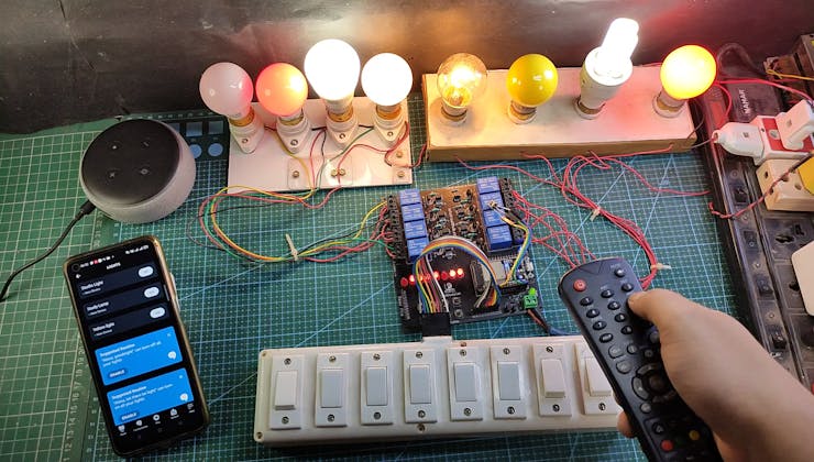
You can always control the relays from the IR remote. For this project, you can use any IR remote.
I will explain how to get the IR codes (HEX codes) from any remote in the following steps.
And if the ESP32 connected with Wi-Fi, then you can also monitor the real-time feedback in the Amazon Alexa App.
Control Relays Manually With Switches:
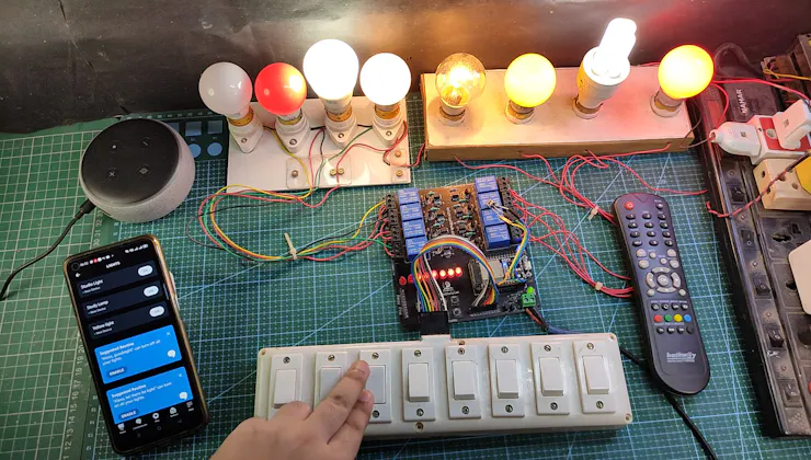
If the WiFi is not available, you can also control the relays from the manual switches.
The ESP32 will check for the WiFi after every 3 seconds. When the WiFi is available, the ESP32 will automatically connect with the WiFi.
Please refer to the circuit diagram to connect the manual switches.
Designing the PCB for ESP32 Projects:
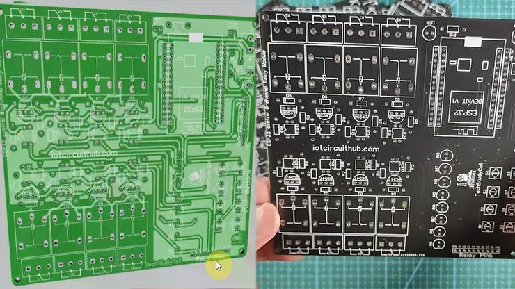
To make the circuit compact and give a professional look, I have designed the PCB after testing all the features of the smart relay module on the breadboard.
You can download the PCB Gerber file of this home automation project from the following link:
https://drive.google.com/uc?export=download&id=1Y8rXnczq6baxAKOrBEE8aro-uqcK0J93
Order the PCB:

After downloading the Garber file you can easily order the PCB
1. Visit https://jlcpcb.com/RAB and Sign in / Sign up
2. Click on the QUOTE NOW button.

3. Click on the "Add your Gerber file" button. Then browse and select the Gerber file you have downloaded.
Uploading the Gerber File and Set the Parameters:

4. Set the required parameter like Quantity, PCB masking color, etc.

5. After selecting all the Parameters for PCB click on SAVE TO CART button.
Select Shipping Address and Payment Mode:

6. Type the Shipping Address.
7. Select the Shipping Method suitable for you.
8. Submit the order and proceed with the payment.
You can also track your order from JLCPCB.com.

My PCBs took 2 days to get manufactured and arrived within a week using the DHL delivery option.
PCBs were well packed and the quality was really good at this affordable price.
Solder All the Components on PCB:

After that, I have soldered all the components as per the circuit diagram.
Then connect the ESP32 board with PCB.
Get the IR Codes (HEX Code) From Remote:

Now, to get the HEX codes from the remote, first, we have to connect the IR receiver output pin with GPIO D35.
and give the 5V across the VCC and GND. The IR receiver must have a metallic casing, otherwise, you may face issues.
Download the code for getting the HEX codes
https://drive.google.com/file/d/1MLJ96CQN3wOuu6iWArsMq9rKsKR5Z3Xi/view?usp=sharing

Then follow the following steps to get the HEX codes
- Install the IRremote library in Arduino IDE
- Download the attached code, and upload it to ESP32.
- Open Serial Monitor with Baud rate 9600.
- Now, press the IR remote button. The respective HEX code will populate in the serial monitor.
Save all the HEX codes in a text file.
Codes for the Blynk ESP32 Home Automation:

Download Code for this ESP32 Blynk home control with Switch (Latched)
https://drive.google.com/file/d/1rEALIDmBMSk7KCWGbDxtfokX7LsM8Ofg/view?usp=sharing
Download Code for this ESP32 Blynk home control with PushButton (Momentary)
https://drive.google.com/file/d/1nwRi9R3mkEK9RV8zuHrp4LUzdANfMAaL/view?usp=sharing
If you use switch (Latched), refer to the code for Switch, and please use the code for the push button for the momentary switch.
Download and install the following libraries in Arduino IDE
- IRremote Libraryhttps://github.com/Arduino-IRremote/Arduino-IRremote
- AceButton Libraryhttps://github.com/bxparks/AceButton
- Espalexa Libraryhttps://github.com/Aircoookie/Espalexa
I have shared the download link of all the libraries in the code.
Program the ESP32 With Arduino IDE:

In the code enter the WiFi name, WiFi password & DevicesNames.
// WiFi Credentials
const char* ssid = "WIFI NAME";
const char* password = "WIFI PASSWORD";

// device names
String Device_1_Name = "Study Lamp";
String Device_2_Name = "CFL";
String Device_3_Name = "Yellow light";
String Device_4_Name = "Night Lamp";
String Device_5_Name = "Studio Light";
String Device_6_Name = "Outdoor Light";
String Device_7_Name = "Kitchen Light";
String Device_8_Name = "Room Light";
Then update the HEX code in the ir_remote function as shown in the tutorial video.
          case 0x80BF49B6:  relayOnOff(1);  break;
          case 0x80BFC936:  relayOnOff(2);  break;
          case 0x80BF33CC:  relayOnOff(3);  break;
          case 0x80BF718E:  relayOnOff(4);  break;
          case 0x80BFF10E:  relayOnOff(5);  break;
          case 0x80BF13EC:  relayOnOff(6);  break;
          case 0x80BF51AE:  relayOnOff(7);  break;
          case 0x80BFD12E:  relayOnOff(8);  break;
After that select the DOIT ESP32 DEVKIT V1 board and the PORT. Then click on the upload button.

While uploading if you see the "Connecting.....___" text, press the BOOT button of ESP32.
Configure the Alexa App for the Smart Home System:

Open Amazon Alexa App and follow the steps:
1. Tap on Devices. Then Tap on the "+" icon.
2. Tap on "Light", then select "Others".
3. Goto Alexa and tap on "DISCOVER DEVICES".
It will take a minute to add devices. During this time the ESP32 should be connected with the WiFi.
4. Tap on "Devices", and tap on "Lights" to see all the devices.

If you face the "no new devices found" error, then restart the Echo Dot and try again.
Testing the PCB With Alexa:

After uploading the code, if the ESP32 connects with the WiFi, the blue LED will turn on.
Then you can control the relay module from Amazon Alexa App.
Connect the Home Appliances:
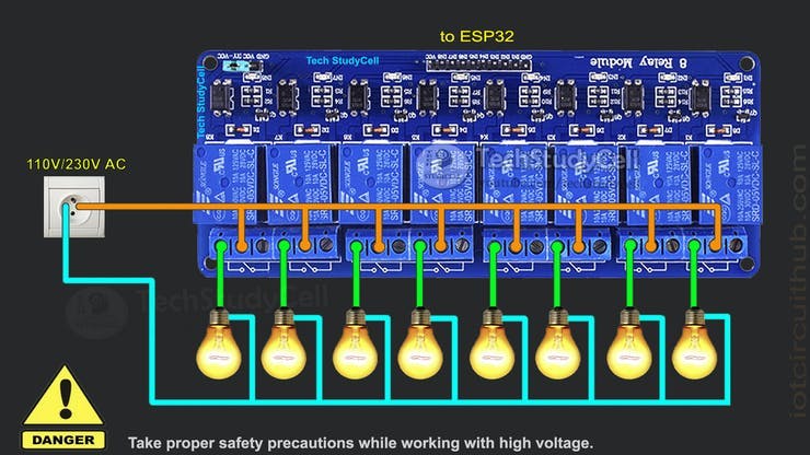
Connect the 8 home appliances as per the circuit diagram. Please take proper safety precautions while working with high voltage.
Connect 5-volt DC supply with the PCB. (I have used my old mobile charger)
Turn ON the Supply:

Turn on the 110V/230V supply and 5V DC supply.
Finally!! the Alexa Home Automation System Is Ready

Now you can control your home appliances in a smart way.
I hope you have liked this Alexa home automation project. I have shared all the required information for this project. I will really appreciate it if you share your valuable feedback.
Also if you have any query please write in the comment section. Thank you & Happy Learning.