Anton Poluektov
-
v2 of the PCB
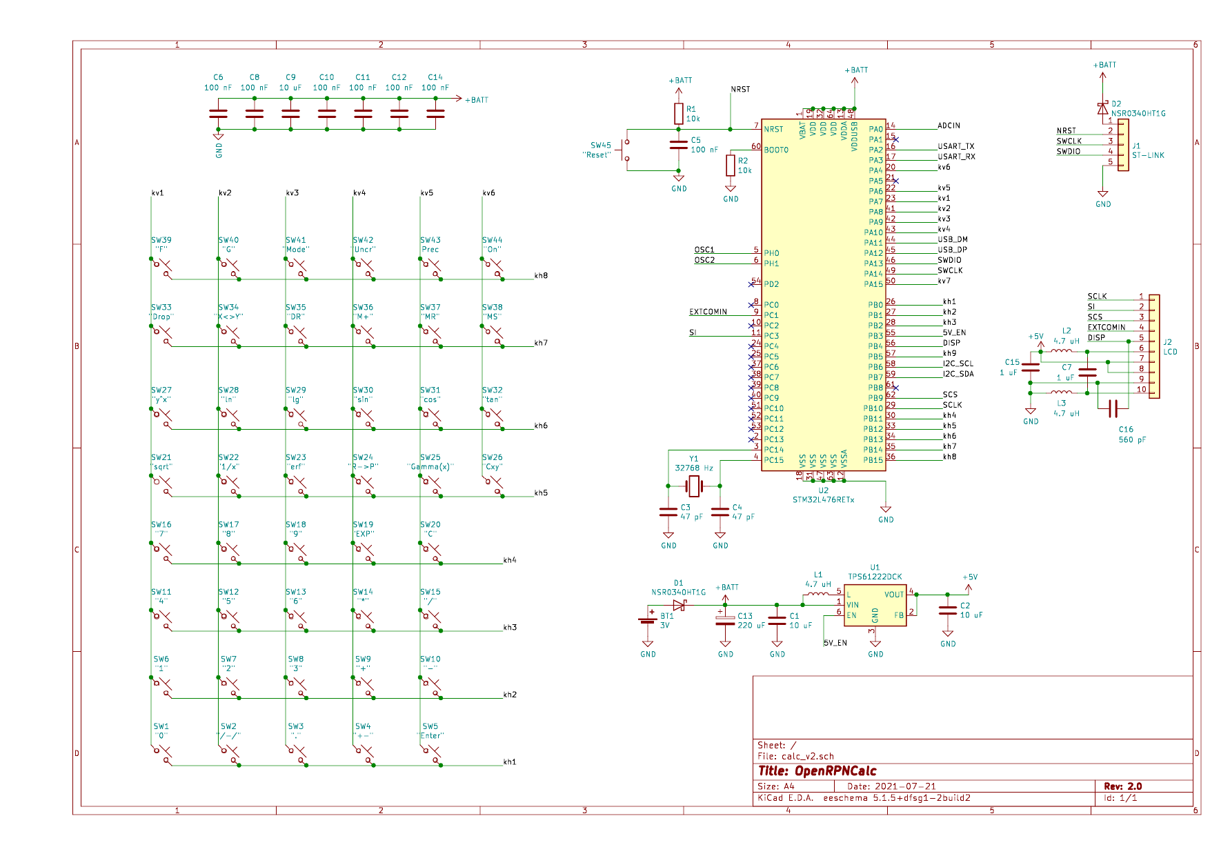
07/21/2021 at 20:00 • 1 commentBased on my experience with the first version, I've made an update of the schematics and the v2 of the PCB is now ordered. Here is the list of changes:
- Additional filtering capacitors for STM (one per each pair of VSS/VDD(A) inputs as per datasheet) and for the LCD (according to LS027B7DH01 datasheet).
- Tantalum capacitor (220 uF) in parallel to the battery to avoid voltage drops during heavy processor activity when the battery is weak.
- Power pin on ST-Link header to power the calculator while flashing or to measure current consumption. Two Schottky diodes as a protection when both ST-Link and battery power is on, and to protect from reverse battery polarity.
- New battery holder (Keystone 1057) which sits in the cutout of the PCB to reduce thickness of the enclosure.
- Improved PCB layout for TPS61222 voltage booster (following datasheet)
- More compact PCB (126x64 mm) with screw holes and cutout for LCD flat cable.
New schematics
![]()
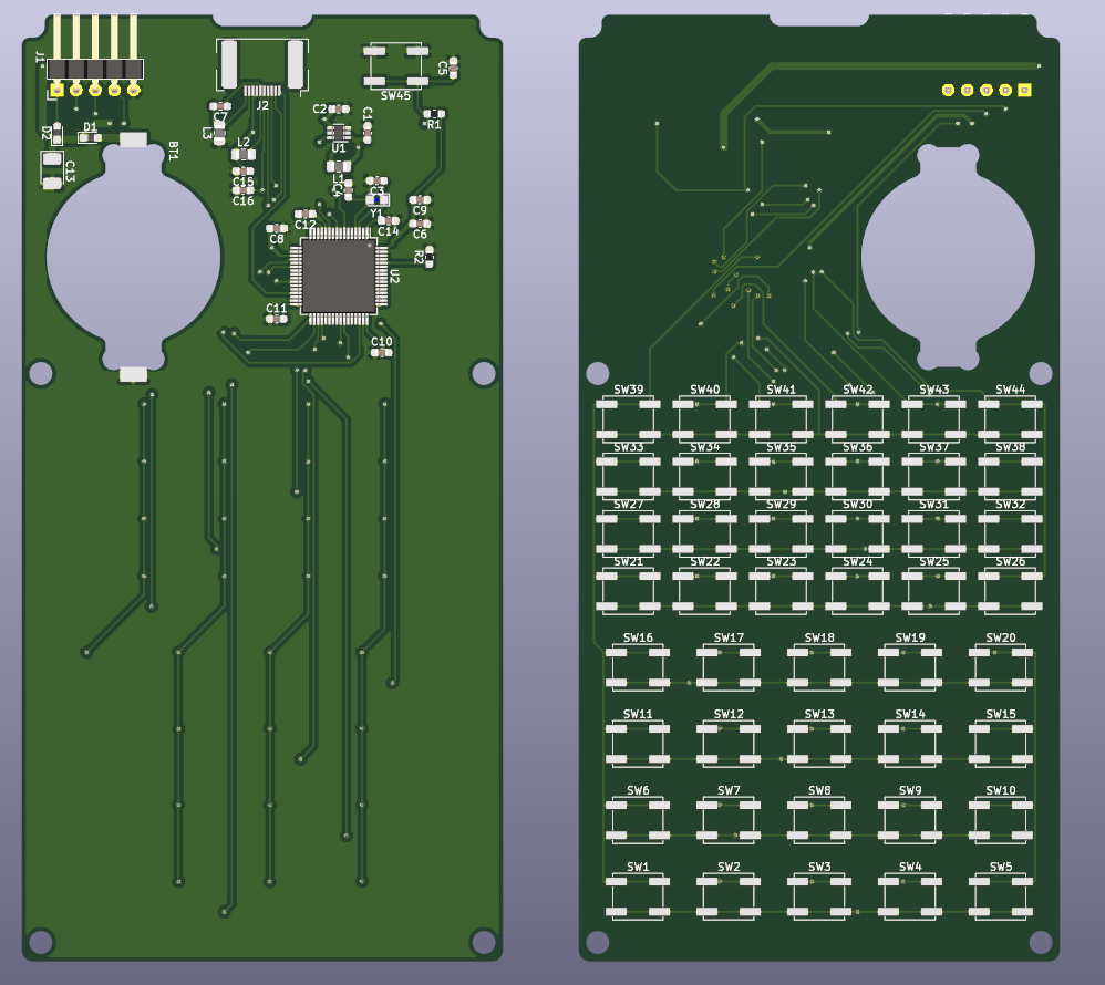
New PCB:
![]()
-
Power consumption: solved
06/19/2021 at 18:10 • 0 commentsI think I've solved all my problems with power consumption being somewhat higher than I hoped. Previously the calculator consumed 40-55 uA of current from the 3V battery, which was to my knowledge a bit on a higher side of what one should expect from STM32L476 in STOP mode.
I discovered that in fact the STM32 was put into STOP1 mode, while there is a more economic one, STOP2, which, however, takes longer startup time (does not matter in my case). STOP2 is activated with the extended HAL function
HAL_PWREx_EnterSTOP2Mode(PWR_STOPENTRY_WFI);
That solves my problem. With STOP2, the STM32 itself draws only 2-3 uA, and that increases to 10-12 uA with LCD on. This must be sufficient to run the calculator from a single CR2032 for several years.
Another small fix I had to do is to add an electrolytic capacitor of 47 uF in parallel to the battery. This fixes occasional resets of the calculator while waking up. As far as I understand, this could happen when the 3V->5V DC converter is powered up and starts to charge the capacitor C2. With the battery being not fresh enough, this could deplete the voltage for a short time below the minimum needed for STM32 to operate, causing it to reset when the voltage is back to normal. Adding extra capacitor with the value a few times higher than C2 fixed this.
-
New key stickers and firmware update
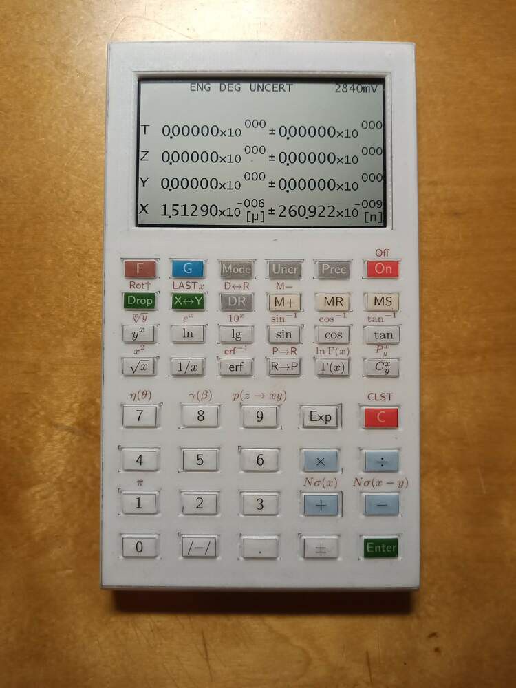
05/28/2021 at 19:08 • 0 commentsPrinted new keyboard stickers: now on a laserjet-printable transparent sticky film (the brand is "Printation Mat Transparent"). Hopefully they will last longer than the paper ones, although with the function set still under development, the longevity is not a real issue.
![]()
Updates in the firmware:
- Added relativistic kinematics functions (uncertainties are not implemented yet for them):
- Conversion between angle and pseudorapidity (eta <-> theta)
- Conversion between beta and gamma factors (gamma <-> beta)
- Center-of-mass momentum for 2-body decay (P(z->xy))
- Added Gamma and log Gamma functions.
- Conversion between degrees and radians.
- Slight reshuffle of function keys.
- Update with ST-Link is now activated with "SHIFT+Reset" (instead of "ON+Reset"). There was a good reason for that: with the almost-flat battery, the MCU could sometimes go into reset when switching calculator on (due to a sudden increase of current consumption). With ST-link connection activated via ON+Reset, it would immediately send MCU into firmware update mode.
- Added relativistic kinematics functions (uncertainties are not implemented yet for them):
-
Firmware issues
05/24/2021 at 20:28 • 0 comments- STOP mode and keyboard scan. When the calculator is ON, the STM32 spends most of its life in STOP mode for minimal power consumption. It can wake up on either external interrupt from the keyboard, or, once a second, on the timer interrupt to toggle the EXTCOMIN signal for Sharp LCD. When the key is pressed, STM wakes up, performs a needed operation, and waits for the key to be released. The waiting cycles are, however, done without sending the MCU to STOP. So, while the button is being pressed, the MCU runs on its full 8 MHz and draws around 4 mA from battery. This needs to be fixed eventually.
- Switching the calculator ON. When the calculator is OFF, all the columns of the keyboard matrix have external interrupts enabled. So, whenever the button is pressed while in OFF, the MCU wakes up, scans the keyboard, and if the button that is pressed is not ON, goes back to STOP. In principle, a better way would be to only enable the interrupt from the column connected to the ON button. However, the straightforward implementation of this appeared to be buggy (it worked, but for some reason the average current draw in OFF was much higher). I've postponed this for now.
-
Issues with PCB and enclosure design
05/24/2021 at 19:30 • 0 comments- The case is relatively thick (12.5mm total thickness). This is limited by the chosen CR2032 battery holder which is itself 5.5mm thick, and of course it should be placed on the back of the PCB, so one should add the thickness of LCD/switches to this value. A better solution would be to make the cutout in the PCB for the battery and find a thinner holder, but I failed so far to find the good one. Alternatively, I could use two smaller 1.5V batteries placed on the front side of the PCB. To be investigated for the next iteration of PCB.
-
Issues with electronics
05/24/2021 at 18:52 • 0 commentsHere are few issues related to electronics:
- The current PCB lacks a few filter capacitors. Normally, STM32 manual recommends a 100 nF capacitor for each VDD-ground pair entering the chip. I had to solder two capacitors in an "ad-hoc" way, PCB needs to be fixed to add them. Also, they could be placed closer to the STM pins.
- 5V booster for the LCD is controller by the 5V_EN signal. The idea was to switch the 5V power to LCD completely when the calculator is OFF. However, it does not work like this due to my wrong understanding of TPS61222 logic. As it is implemented currently, when the calculator goes OFF, LCD receives 3V from the battery instead of 5V (the booster is switched off, but still supplies battery power). This has to be fixed by adding a transistor to decouple the TPS61222 and LCD from the battery.
- By the way, it appears that Sharp memory LCD works nicely from 3V instead of nominal 5V as indicated in datasheet. Maybe 5V booster can be removed completely?
- The circuitry around TPS61222 does not follow exactly the PCB design pattern from the datasheet (conductors are not thick enough, inductor and capacitors are not close enough to the chip). While it works stably, the PCB should still be improved.
- A couple of filter capacitors are missing near the LCD connector as well. To be fixed.
OpenRPNCalc
Open-source and open-hardware custom scientific RPN calculator