0%
0%
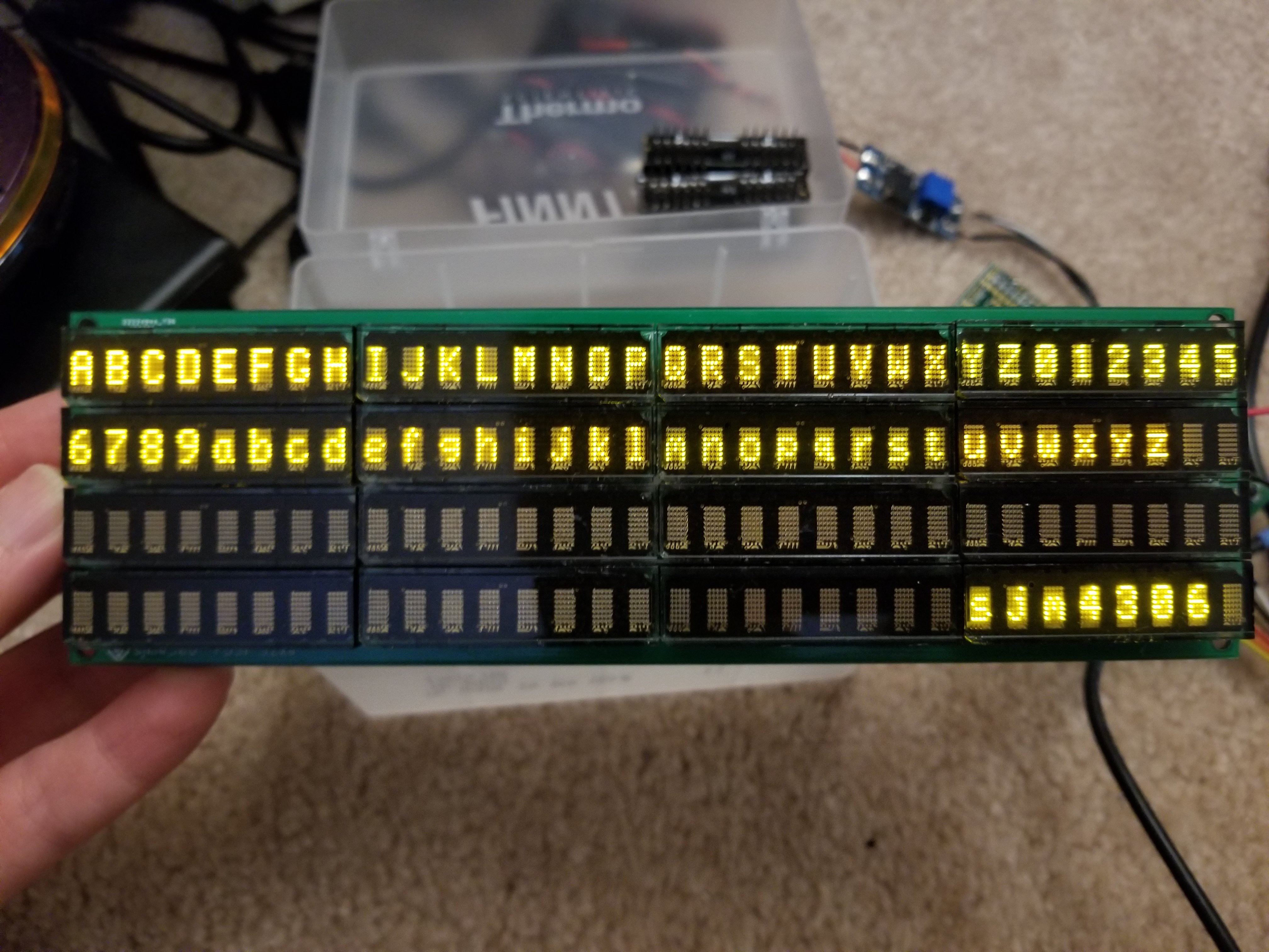
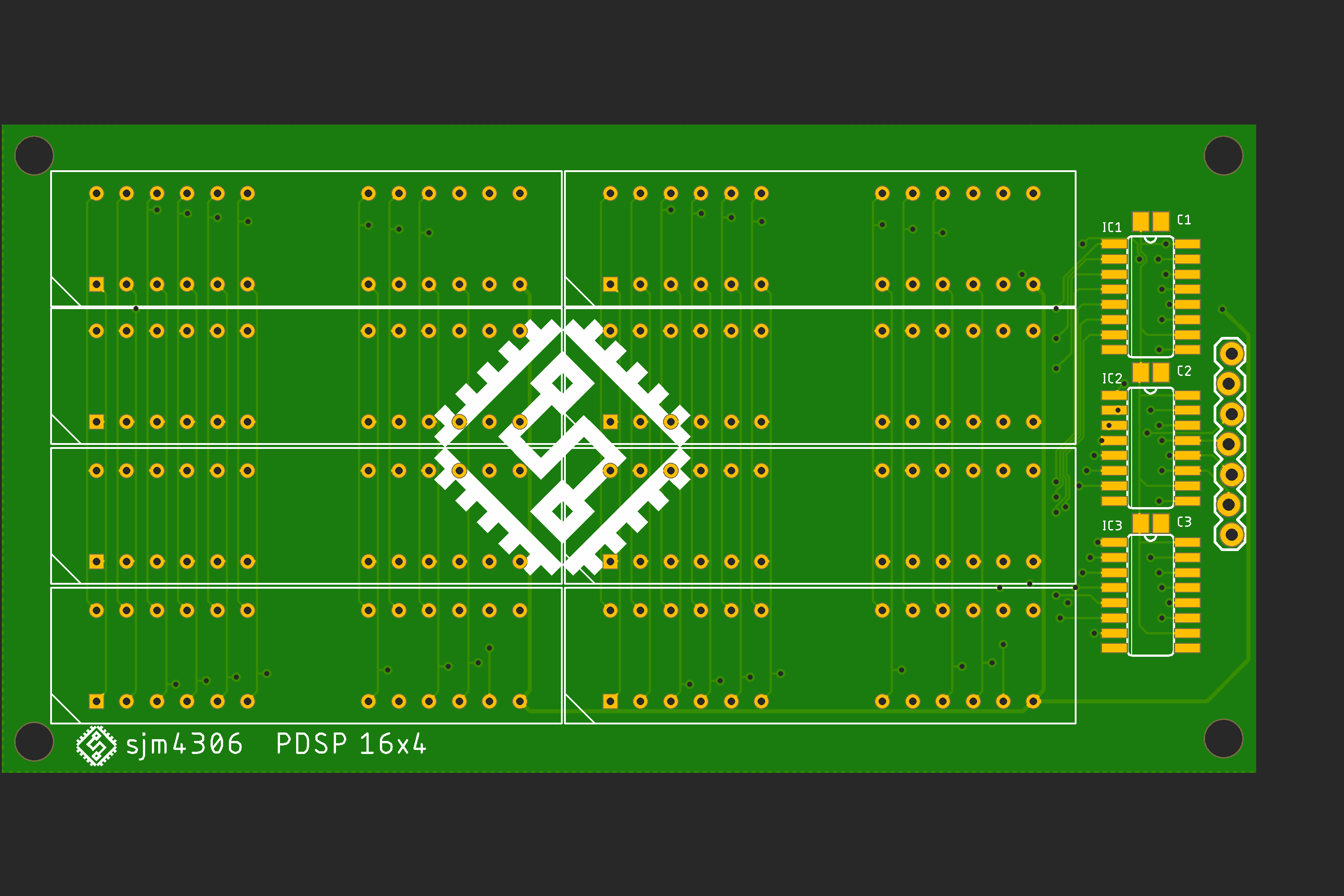
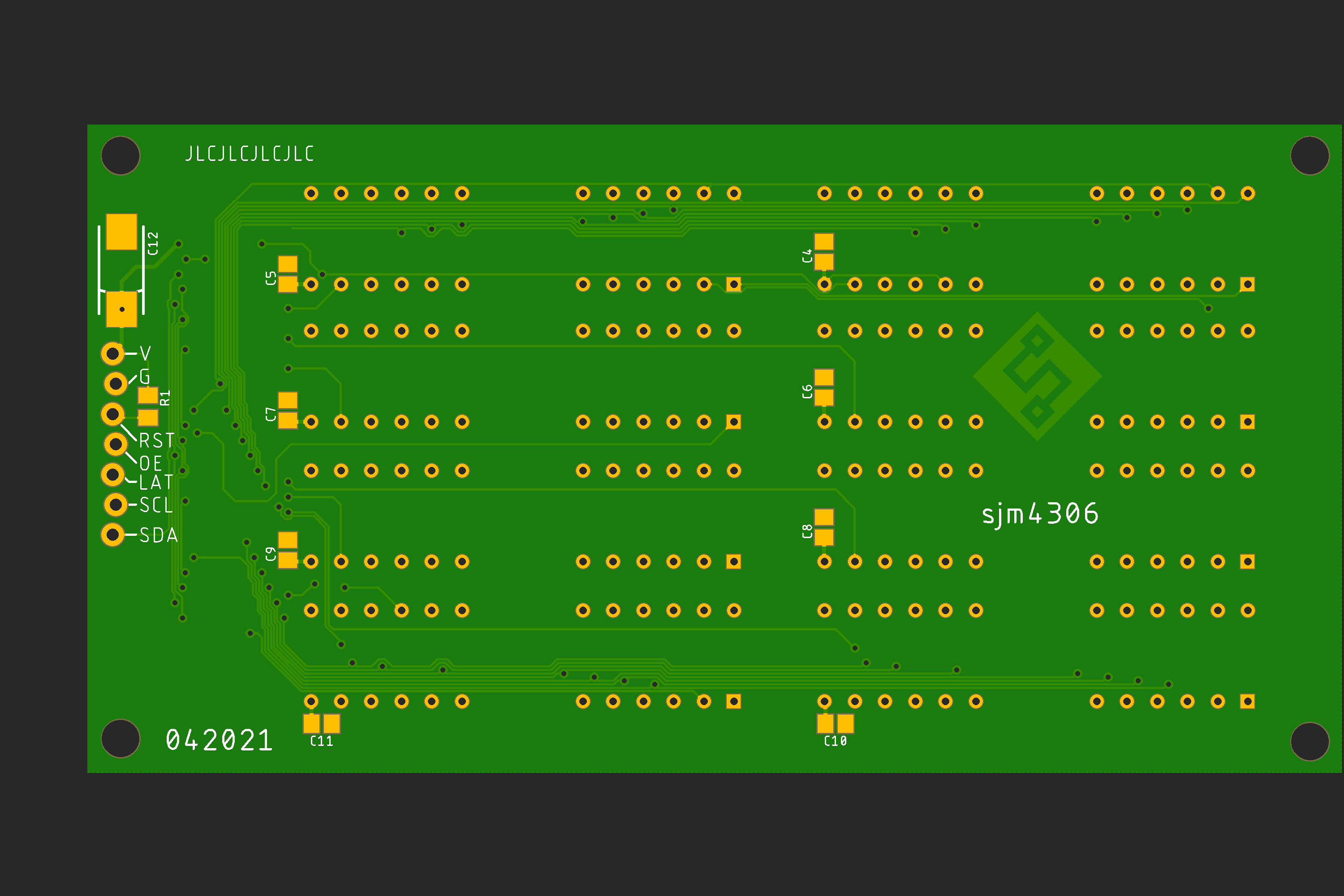
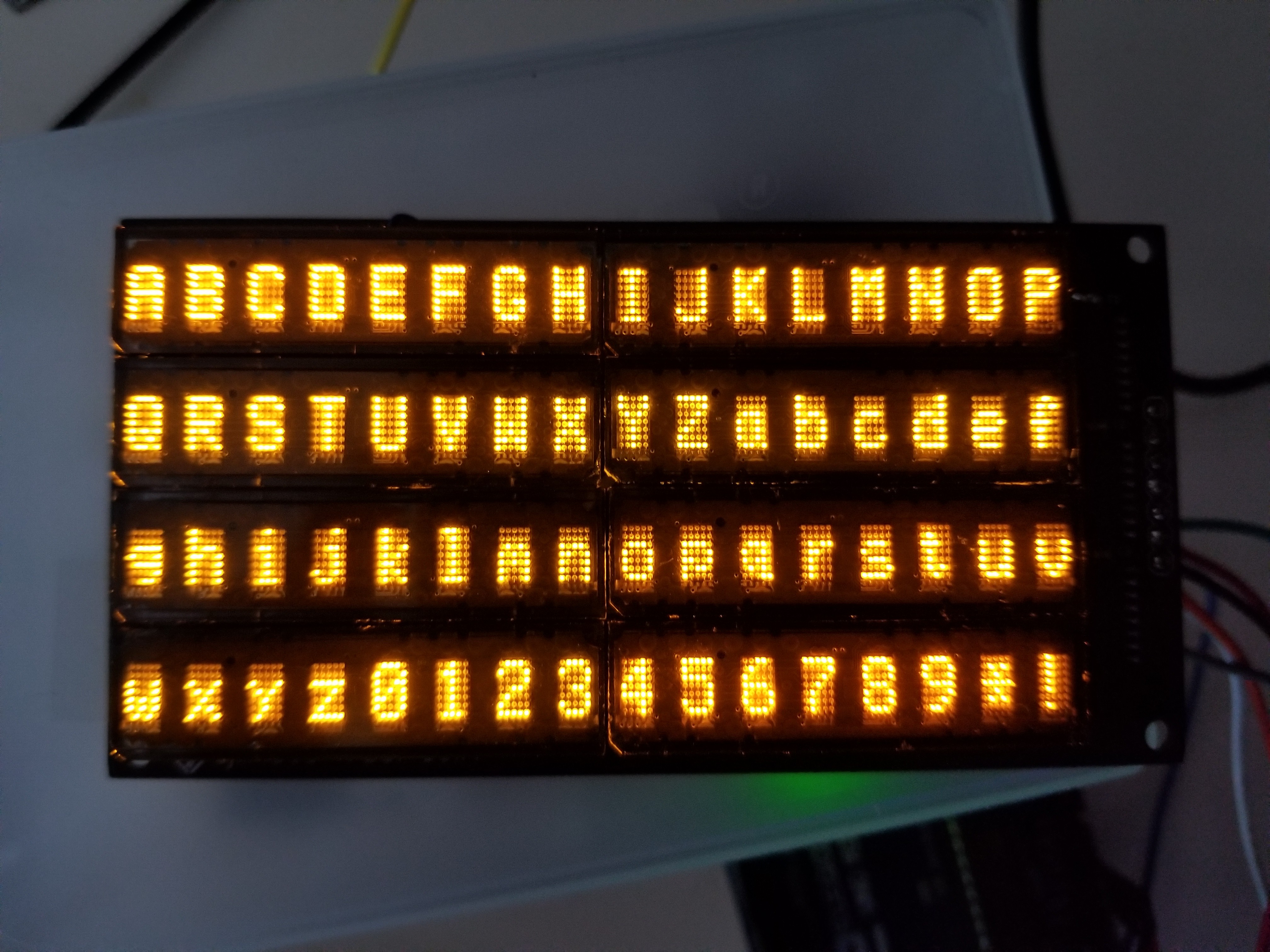
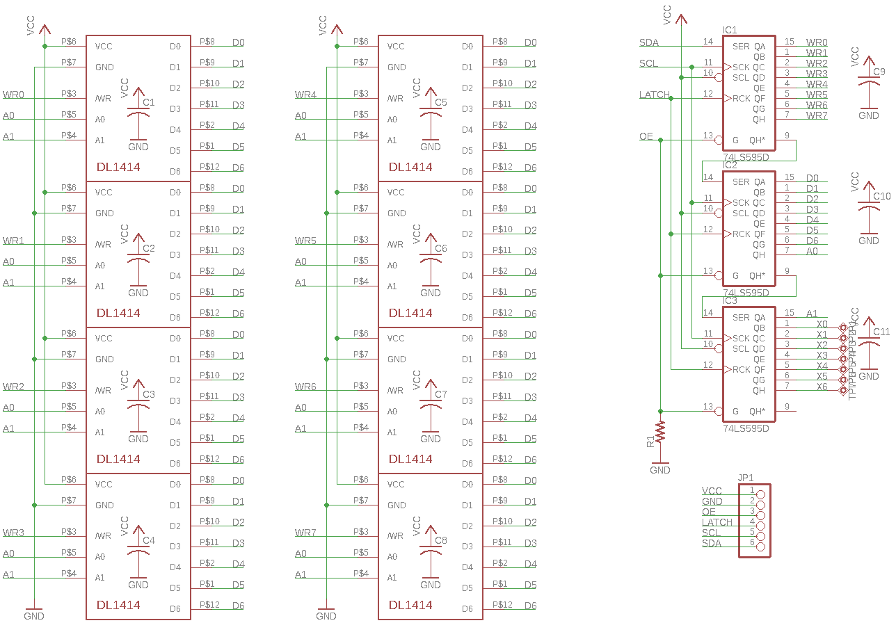
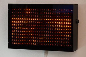
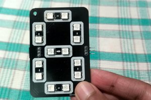
Retro Alphanumeric LED Displays + Libraries
Exactly as the title says, these are a few retro led displays I've strung together to make 16x2 modules with some software I wrote
 sjm4306
Become a Hackaday.io member
Already have an account? Log in.
Just one more thing
To make the experience fit your profile, pick a username and tell us what interests you.
Pick an awesome username
hackaday.io/
Your profile's URL: hackaday.io/username. Max 25 alphanumeric characters.
Pick a few interests
Projects that share your interests
People that share your interests

 Chris Combs
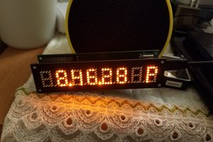
 SAYANTAN PAL
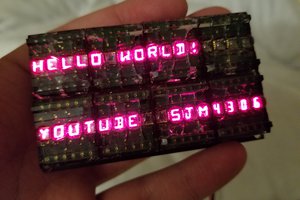
i have lots of Simens PD2437, do you think they will work the same way? i would love to get a use for them! this is an awesome project!